EP4465543A2 - Dispositif électronique pliable comprenant une antenne - Google Patents
Dispositif électronique pliable comprenant une antenne Download PDFInfo
- Publication number
- EP4465543A2 EP4465543A2 EP24203836.2A EP24203836A EP4465543A2 EP 4465543 A2 EP4465543 A2 EP 4465543A2 EP 24203836 A EP24203836 A EP 24203836A EP 4465543 A2 EP4465543 A2 EP 4465543A2
- Authority
- EP
- European Patent Office
- Prior art keywords
- electronic device
- housing
- folded state
- housing structure
- foldable
- Prior art date
- Legal status (The legal status is an assumption and is not a legal conclusion. Google has not performed a legal analysis and makes no representation as to the accuracy of the status listed.)
- Pending
Links
Images








Classifications
-
- G—PHYSICS
- G09—EDUCATION; CRYPTOGRAPHY; DISPLAY; ADVERTISING; SEALS
- G09F—DISPLAYING; ADVERTISING; SIGNS; LABELS OR NAME-PLATES; SEALS
- G09F9/00—Indicating arrangements for variable information in which the information is built-up on a support by selection or combination of individual elements
- G09F9/30—Indicating arrangements for variable information in which the information is built-up on a support by selection or combination of individual elements in which the desired character or characters are formed by combining individual elements
- G09F9/301—Indicating arrangements for variable information in which the information is built-up on a support by selection or combination of individual elements in which the desired character or characters are formed by combining individual elements flexible foldable or roll-able electronic displays, e.g. thin LCD, OLED
-
- H—ELECTRICITY
- H04—ELECTRIC COMMUNICATION TECHNIQUE
- H04M—TELEPHONIC COMMUNICATION
- H04M1/00—Substation equipment, e.g. for use by subscribers
- H04M1/02—Constructional features of telephone sets
- H04M1/0202—Portable telephone sets, e.g. cordless phones, mobile phones or bar type handsets
- H04M1/0206—Portable telephones comprising a plurality of mechanically joined movable body parts, e.g. hinged housings
- H04M1/0208—Portable telephones comprising a plurality of mechanically joined movable body parts, e.g. hinged housings characterized by the relative motions of the body parts
- H04M1/0214—Foldable telephones, i.e. with body parts pivoting to an open position around an axis parallel to the plane they define in closed position
- H04M1/0216—Foldable in one direction, i.e. using a one degree of freedom hinge
-
- G—PHYSICS
- G06—COMPUTING OR CALCULATING; COUNTING
- G06F—ELECTRIC DIGITAL DATA PROCESSING
- G06F1/00—Details not covered by groups G06F3/00 - G06F13/00 and G06F21/00
- G06F1/16—Constructional details or arrangements
- G06F1/1613—Constructional details or arrangements for portable computers
- G06F1/1615—Constructional details or arrangements for portable computers with several enclosures having relative motions, each enclosure supporting at least one I/O or computing function
- G06F1/1616—Constructional details or arrangements for portable computers with several enclosures having relative motions, each enclosure supporting at least one I/O or computing function with folding flat displays, e.g. laptop computers or notebooks having a clamshell configuration, with body parts pivoting to an open position around an axis parallel to the plane they define in closed position
-
- G—PHYSICS
- G06—COMPUTING OR CALCULATING; COUNTING
- G06F—ELECTRIC DIGITAL DATA PROCESSING
- G06F1/00—Details not covered by groups G06F3/00 - G06F13/00 and G06F21/00
- G06F1/16—Constructional details or arrangements
- G06F1/1613—Constructional details or arrangements for portable computers
- G06F1/1633—Constructional details or arrangements of portable computers not specific to the type of enclosures covered by groups G06F1/1615 - G06F1/1626
- G06F1/1637—Details related to the display arrangement, including those related to the mounting of the display in the housing
- G06F1/1641—Details related to the display arrangement, including those related to the mounting of the display in the housing the display being formed by a plurality of foldable display components
-
- G—PHYSICS
- G06—COMPUTING OR CALCULATING; COUNTING
- G06F—ELECTRIC DIGITAL DATA PROCESSING
- G06F1/00—Details not covered by groups G06F3/00 - G06F13/00 and G06F21/00
- G06F1/16—Constructional details or arrangements
- G06F1/1613—Constructional details or arrangements for portable computers
- G06F1/1633—Constructional details or arrangements of portable computers not specific to the type of enclosures covered by groups G06F1/1615 - G06F1/1626
- G06F1/1637—Details related to the display arrangement, including those related to the mounting of the display in the housing
- G06F1/1652—Details related to the display arrangement, including those related to the mounting of the display in the housing the display being flexible, e.g. mimicking a sheet of paper, or rollable
-
- G—PHYSICS
- G06—COMPUTING OR CALCULATING; COUNTING
- G06F—ELECTRIC DIGITAL DATA PROCESSING
- G06F1/00—Details not covered by groups G06F3/00 - G06F13/00 and G06F21/00
- G06F1/16—Constructional details or arrangements
- G06F1/1613—Constructional details or arrangements for portable computers
- G06F1/1633—Constructional details or arrangements of portable computers not specific to the type of enclosures covered by groups G06F1/1615 - G06F1/1626
- G06F1/1656—Details related to functional adaptations of the enclosure, e.g. to provide protection against EMI, shock, water, or to host detachable peripherals like a mouse or removable expansions units like PCMCIA cards, or to provide access to internal components for maintenance or to removable storage supports like CDs or DVDs, or to mechanically mount accessories
-
- G—PHYSICS
- G06—COMPUTING OR CALCULATING; COUNTING
- G06F—ELECTRIC DIGITAL DATA PROCESSING
- G06F1/00—Details not covered by groups G06F3/00 - G06F13/00 and G06F21/00
- G06F1/16—Constructional details or arrangements
- G06F1/1613—Constructional details or arrangements for portable computers
- G06F1/1633—Constructional details or arrangements of portable computers not specific to the type of enclosures covered by groups G06F1/1615 - G06F1/1626
- G06F1/1675—Miscellaneous details related to the relative movement between the different enclosures or enclosure parts
- G06F1/1681—Details related solely to hinges
-
- G—PHYSICS
- G06—COMPUTING OR CALCULATING; COUNTING
- G06F—ELECTRIC DIGITAL DATA PROCESSING
- G06F1/00—Details not covered by groups G06F3/00 - G06F13/00 and G06F21/00
- G06F1/16—Constructional details or arrangements
- G06F1/1613—Constructional details or arrangements for portable computers
- G06F1/1633—Constructional details or arrangements of portable computers not specific to the type of enclosures covered by groups G06F1/1615 - G06F1/1626
- G06F1/1684—Constructional details or arrangements related to integrated I/O peripherals not covered by groups G06F1/1635 - G06F1/1675
- G06F1/1698—Constructional details or arrangements related to integrated I/O peripherals not covered by groups G06F1/1635 - G06F1/1675 the I/O peripheral being a sending/receiving arrangement to establish a cordless communication link, e.g. radio or infrared link, integrated cellular phone
-
- H—ELECTRICITY
- H01—ELECTRIC ELEMENTS
- H01Q—ANTENNAS, i.e. RADIO AERIALS
- H01Q1/00—Details of, or arrangements associated with, antennas
- H01Q1/12—Supports; Mounting means
- H01Q1/22—Supports; Mounting means by structural association with other equipment or articles
- H01Q1/24—Supports; Mounting means by structural association with other equipment or articles with receiving set
- H01Q1/241—Supports; Mounting means by structural association with other equipment or articles with receiving set used in mobile communications, e.g. GSM
-
- H—ELECTRICITY
- H01—ELECTRIC ELEMENTS
- H01Q—ANTENNAS, i.e. RADIO AERIALS
- H01Q1/00—Details of, or arrangements associated with, antennas
- H01Q1/12—Supports; Mounting means
- H01Q1/22—Supports; Mounting means by structural association with other equipment or articles
- H01Q1/24—Supports; Mounting means by structural association with other equipment or articles with receiving set
- H01Q1/241—Supports; Mounting means by structural association with other equipment or articles with receiving set used in mobile communications, e.g. GSM
- H01Q1/242—Supports; Mounting means by structural association with other equipment or articles with receiving set used in mobile communications, e.g. GSM specially adapted for hand-held use
- H01Q1/243—Supports; Mounting means by structural association with other equipment or articles with receiving set used in mobile communications, e.g. GSM specially adapted for hand-held use with built-in antennas
-
- H—ELECTRICITY
- H01—ELECTRIC ELEMENTS
- H01Q—ANTENNAS, i.e. RADIO AERIALS
- H01Q21/00—Antenna arrays or systems
- H01Q21/30—Combinations of separate antenna units operating in different wavebands and connected to a common feeder system
-
- H—ELECTRICITY
- H01—ELECTRIC ELEMENTS
- H01Q—ANTENNAS, i.e. RADIO AERIALS
- H01Q9/00—Electrically-short antennas having dimensions not more than twice the operating wavelength and consisting of conductive active radiating elements
- H01Q9/04—Resonant antennas
- H01Q9/30—Resonant antennas with feed to end of elongated active element, e.g. unipole
- H01Q9/42—Resonant antennas with feed to end of elongated active element, e.g. unipole with folded element, the folded parts being spaced apart a small fraction of the operating wavelength
-
- H—ELECTRICITY
- H04—ELECTRIC COMMUNICATION TECHNIQUE
- H04B—TRANSMISSION
- H04B1/00—Details of transmission systems, not covered by a single one of groups H04B3/00 - H04B13/00; Details of transmission systems not characterised by the medium used for transmission
- H04B1/38—Transceivers, i.e. devices in which transmitter and receiver form a structural unit and in which at least one part is used for functions of transmitting and receiving
- H04B1/3827—Portable transceivers
- H04B1/3888—Arrangements for carrying or protecting transceivers
-
- H—ELECTRICITY
- H04—ELECTRIC COMMUNICATION TECHNIQUE
- H04B—TRANSMISSION
- H04B1/00—Details of transmission systems, not covered by a single one of groups H04B3/00 - H04B13/00; Details of transmission systems not characterised by the medium used for transmission
- H04B1/38—Transceivers, i.e. devices in which transmitter and receiver form a structural unit and in which at least one part is used for functions of transmitting and receiving
- H04B1/40—Circuits
-
- H—ELECTRICITY
- H04—ELECTRIC COMMUNICATION TECHNIQUE
- H04M—TELEPHONIC COMMUNICATION
- H04M1/00—Substation equipment, e.g. for use by subscribers
- H04M1/02—Constructional features of telephone sets
- H04M1/0202—Portable telephone sets, e.g. cordless phones, mobile phones or bar type handsets
- H04M1/0206—Portable telephones comprising a plurality of mechanically joined movable body parts, e.g. hinged housings
- H04M1/0208—Portable telephones comprising a plurality of mechanically joined movable body parts, e.g. hinged housings characterized by the relative motions of the body parts
- H04M1/0214—Foldable telephones, i.e. with body parts pivoting to an open position around an axis parallel to the plane they define in closed position
- H04M1/0222—Foldable in two directions, i.e. using a two degree of freedom hinge
-
- H—ELECTRICITY
- H04—ELECTRIC COMMUNICATION TECHNIQUE
- H04M—TELEPHONIC COMMUNICATION
- H04M1/00—Substation equipment, e.g. for use by subscribers
- H04M1/02—Constructional features of telephone sets
- H04M1/0202—Portable telephone sets, e.g. cordless phones, mobile phones or bar type handsets
- H04M1/026—Details of the structure or mounting of specific components
-
- H—ELECTRICITY
- H04—ELECTRIC COMMUNICATION TECHNIQUE
- H04M—TELEPHONIC COMMUNICATION
- H04M1/00—Substation equipment, e.g. for use by subscribers
- H04M1/02—Constructional features of telephone sets
- H04M1/0202—Portable telephone sets, e.g. cordless phones, mobile phones or bar type handsets
- H04M1/026—Details of the structure or mounting of specific components
- H04M1/0266—Details of the structure or mounting of specific components for a display module assembly
- H04M1/0268—Details of the structure or mounting of specific components for a display module assembly including a flexible display panel
-
- H—ELECTRICITY
- H01—ELECTRIC ELEMENTS
- H01Q—ANTENNAS, i.e. RADIO AERIALS
- H01Q1/00—Details of, or arrangements associated with, antennas
- H01Q1/08—Means for collapsing antennas or parts thereof
-
- H—ELECTRICITY
- H01—ELECTRIC ELEMENTS
- H01Q—ANTENNAS, i.e. RADIO AERIALS
- H01Q1/00—Details of, or arrangements associated with, antennas
- H01Q1/12—Supports; Mounting means
- H01Q1/22—Supports; Mounting means by structural association with other equipment or articles
-
- H—ELECTRICITY
- H04—ELECTRIC COMMUNICATION TECHNIQUE
- H04M—TELEPHONIC COMMUNICATION
- H04M1/00—Substation equipment, e.g. for use by subscribers
- H04M1/02—Constructional features of telephone sets
- H04M1/0202—Portable telephone sets, e.g. cordless phones, mobile phones or bar type handsets
- H04M1/0206—Portable telephones comprising a plurality of mechanically joined movable body parts, e.g. hinged housings
- H04M1/0208—Portable telephones comprising a plurality of mechanically joined movable body parts, e.g. hinged housings characterized by the relative motions of the body parts
- H04M1/0214—Foldable telephones, i.e. with body parts pivoting to an open position around an axis parallel to the plane they define in closed position
Definitions
- the disclosure relates to a foldable electronic device including an antenna.
- an electronic device may be formed to have a bending structure or a folding structure.
- an electronic device may include a flip cover, a dual display, a flexible display, and the like.
- An electronic device may provide mobile communication service using an antenna.
- the antenna of the electronic device may be arranged in a portion of area of the inside and/or outside of the housing.
- the housing of a foldable electronic device may be in a folded state or in a flat state around a hinge structure.
- the outer peripheral side surface of the housing of the foldable electronic device may be made of a metallic material, and a part of the metallic material may be used as an antenna.
- An electronic device may include: a foldable housing; a flexible display disposed on the foldable housing wherein at least a part of the flexible display is configured to be folded; and a frame disposed on a boundary portion of the flexible display and coupled to a side member of the foldable housing.
- the side member may include a conductive portion electrically connected to a communication circuit, and the frame may include a low-permittivity material.
- a foldable electronic device may include: a first housing including a first surface, a second surface facing a direction opposite the first surface, and a first side housing surrounding at least a part of a first space between the first surface and the second surface; a second housing including a third surface facing the first surface of the first housing in a folded state of the foldable electronic device, a fourth surface facing a direction opposite the third surface, and a second side housing surrounding at least a part of a second space between the third surface and the fourth surface; a hinge arranged between the first housing and the second housing and defining a folding axis; a flexible display exposed through the first surface and the third surface; and a communication circuit disposed in the first space and/or the second space.
- Each of the first side housing and the second side housing may include a conductive portion. At least a part of the conductive portion of the first side housing may be electrically connected to the communication circuit.
- Various example embodiments may provide a foldable electronic device capable of reducing degradation of performance of the antenna while the electronic device is in a folded state.
- Fig. 1 is a block diagram illustrating an electronic device 101 in a network environment 100 according to various embodiments.
- the electronic device 101 in the network environment 100 may communicate with an electronic device 102 via a first network 198 (e.g., a short-range wireless communication network), or an electronic device 104 or a server 108 via a second network 199 (e.g., a long-range wireless communication network).
- the electronic device 101 may communicate with the electronic device 104 via the server 108.
- the auxiliary processor 123 may control at least some of functions or states related to at least one component (e.g., the display device 160, the sensor module 176, or the communication module 190) among the components of the electronic device 101, instead of the main processor 121 while the main processor 121 is in an inactive (e.g., sleep) state, or together with the main processor 121 while the main processor 121 is in an active state (e.g., executing an application).
- the auxiliary processor 123 e.g., an image signal processor or a communication processor
- the display device 160 may visually provide information to the outside (e.g., a user) of the electronic device 101.
- the display device 160 may include, for example, a display, a hologram device, or a projector and control circuitry to control a corresponding one of the display, hologram device, and projector.
- the display device 160 may include touch circuitry adapted to detect a touch, or sensor circuitry (e.g., a pressure sensor) adapted to measure the intensity of force incurred by the touch.
- the audio module 170 may convert a sound into an electrical signal and vice versa. According to an embodiment, the audio module 170 may obtain the sound via the input device 150, or output the sound via the sound output device 155 or a headphone of an external electronic device (e.g., an electronic device 102) directly (e.g., wiredly) or wirelessly coupled with the electronic device 101.
- an external electronic device e.g., an electronic device 102
- directly e.g., wiredly
- wirelessly e.g., wirelessly
- the sensor module 176 may detect an operational state (e.g., power or temperature) of the electronic device 101 or an environmental state (e.g., a state of a user) external to the electronic device 101, and then generate an electrical signal or data value corresponding to the detected state.
- the sensor module 176 may include, for example, a gesture sensor, a gyro sensor, an atmospheric pressure sensor, a magnetic sensor, an acceleration sensor, a grip sensor, a proximity sensor, a color sensor, an infrared (IR) sensor, a biometric sensor, a temperature sensor, a humidity sensor, or an illuminance sensor.
- a connecting terminal 178 may include a connector via which the electronic device 101 may be physically connected with the external electronic device (e.g., the electronic device 102).
- the connecting terminal 178 may include, for example, a HDMI connector, a USB connector, a SD card connector, or an audio connector (e.g., a headphone connector).
- the haptic module 179 may convert an electrical signal into a mechanical stimulus (e.g., a vibration or a movement) or electrical stimulus which may be recognized by a user via his tactile sensation or kinesthetic sensation.
- the haptic module 179 may include, for example, a motor, a piezoelectric element, or an electric stimulator.
- the power management module 188 may manage power supplied to the electronic device 101.
- the power management module 188 may be implemented as at least part of, for example, a power management integrated circuit (PMIC).
- PMIC power management integrated circuit
- the battery 189 may supply power to at least one component of the electronic device 101.
- the battery 189 may include, for example, a primary cell which is not rechargeable, a secondary cell which is rechargeable, or a fuel cell.
- the signal or the power may then be transmitted or received between the communication module 190 and the external electronic device via the selected at least one antenna.
- another component e.g., a radio frequency integrated circuit (RFIC)
- RFIC radio frequency integrated circuit
- the display unit 20 may include a display 200 and at least one plate or layer 240 on which the display 200 is seated.
- a plate 240 may be arranged between the display 200 and the bracket assembly 30.
- the display 200 may be arranged on at least a part of a surface of the plate 240 (for example, the upper surface with reference to FIG. 4 ).
- the plate 240 may be formed in a shape corresponding to that of the display 200.
- the plate 240 may have a partial area formed in a shape corresponding to a notch 204 in the display 200.
- the wire member 430 and the hinge structure 340 may be arranged inside the bracket assembly 30.
- the wire member 430 may be arranged in a direction (for example, the x-axis direction) across the first bracket 410 and the second bracket 420.
- the wire member 430 may be arranged in a direction (for example, the x-axis direction) perpendicular to the folding axis (for example, the y-axis or the folding axis (A) of FIG. 2 ) of the folding area 203 of the electronic device 10.
- the first housing structure 310 and the second housing structure 320 may be assembled to be coupled to both sides of the bracket assembly 30, respectively, while the display unit 20 remains coupled to the bracket assembly 30. As will be described later, the first housing structure 310 and the second housing structure 320 may slide along both sides of the bracket assembly 30, respectively, so as to be coupled to the bracket assembly 30.
- the first rotating support surface 312 and the second rotating support surface 322 may cover the hinge cover 330 such that the hinge cover 330 is not exposed to the rear surface of the electronic device 10, or is exposed to a lesser extent.
- the first rotating support surface 312 and the second rotating support surface 322 may rotate along the curved surface included in the hinge cover 330 such that the hinge cover 330 is exposed to the rear surface of the electronic device 10 to the largest extent.
- FIG. 5 is a diagram illustrating a first side housing and a second side housing of an example electronic device in a flat state according to an embodiment.
- an electronic device 10 may include a first housing structure 310 and a second housing structure 320 arranged on both sides with reference to a hinge structure 340 that defines a folding axis A.
- a mechanism referred to as a first side housing 343 may be arranged on a side surface of the first housing structure 310
- a mechanism referred to as a second side housing 353 may be arranged on a side surface of the second housing structure 320.
- the second side housing 353 may include a fourth side surface 353a which is parallel with the folding axis (axis A); a fifth side surface 353b which is connected to one side of the fourth side surface 353a (for example, the lower side of the fourth side surface 353a illustrated in FIG. 5 ), and which is arranged adjacent to the second side surface 343b when the electronic device 10 is in a folded state; and a sixth side surface 353c which is connected to the other side of the fourth side surface353a (for example, the upper side of the fourth side surface 353a illustrated in FIG. 5 ), and which is arranged adjacent to the third side surface 343c when the electronic device 10 is in a folded state.
- a fourth side surface 353a which is parallel with the folding axis (axis A)
- a fifth side surface 353b which is connected to one side of the fourth side surface 353a (for example, the lower side of the fourth side surface 353a illustrated in FIG. 5 ), and which is arranged adjacent to the second side surface 3
- each of the first side housing 343 and the second side housing 353 may include a conductive portion.
- the first side housing 343 may include a metallic material except for a part of the second side surface 343b and a part of the third side surface 343c.
- the second side housing 353 may include a metallic material except for a part of the fifth side surface 353b and a part of the sixth side surface 353c.
- the second side surface 343b may include multiple conductive portions 531, 532, and 533 and at least one nonconductive portion 591 and 592 arranged between the multiple conductive portions 531, 532, and 533.
- the second side surface 343b may include a first conductive portion 531, a second conductive portion 532 arranged on one side of the first conductive portion 531 (for example, the left side of the first conductive portion 531 illustrated in FIG. 5 ); a third conductive portion 533 arranged on the other side of the first conductive portion 531 (for example, the right side of the first conductive portion 531 illustrated in FIG.
- the third side surface 343c may include a first conductive portion 531, a second conductive portion 532 arranged on one side of the first conductive portion 531 (for example, the left side of the first conductive portion 531 illustrated in FIG. 5 ); a third conductive portion 533 arranged on the other side of the first conductive portion 531 (for example, the right side of the first conductive portion 531 illustrated in FIG.
- the sixth side surface 353c may include a fourth conductive portion 541; a fifth conductive portion 542 arranged on one side of the fourth conductive portion 541 (for example, the left side of the fourth conductive portion 541 illustrated in FIG. 5 ); a sixth conductive portion 543 arranged on the other side of the fourth conductive portion 541 (for example, the right side of the fourth conductive portion 541 illustrated in FIG.
- each of the first conductive portion 531, the second conductive portion 532, and the third conductive portion 533 arranged on the second side surface 343b and/or the third side surface 343c may be a radiator (for example, an antenna) which radiates RF signals output from a communication module (for example, the communication module 190 of FIG. 1 ).
- the first conductive portion 531 may be a first antenna ANT #1 for resonating a first RF signal output from the communication module 190; the second conductive portion 532 may be a second antenna ANT #2 for resonating a second RF signal output from the communication module 190; and the third conductive portion 533 may be a third antenna ANT #3 for resonating a third RF signal output from the communication module 190.
- the first side surface 343a may include a seventh conductive portion 571, and a part 571a of either side of the seventh conductive portion 571 may be used as an antenna.
- a part of one side of the seventh conductive portion 571 (for example, the lower side of the seventh conductive portion 571 illustrated in FIG. 5 ) may be connected to the second conductive portion 532 arranged on the second side surface 343b and used as a second antenna ANT#2.
- a part of the other side of the seventh conductive portion 571 (for example, the upper side of the seventh conductive portion 571 illustrated in FIG. 5 ) may be connected to the second conductive portion 532 arranged on the third side surface 343c and used as a second antenna ANT#2.
- the seventh conductive portion 571 may be connected to the ground 562 at a first point 581 adjacent to the periphery of one side of the seventh conductive portion 571 (for example, the lower side of the seventh conductive portion 571 illustrated in FIG. 5 ) and may be connected to the ground 562 at a second point 582 adjacent to the periphery of the other side of the seventh conductive portion 571 (for example, the upper side of the seventh conductive portion 571 illustrated in FIG. 5 ); and the portion 571b between the first point 581 and the second point 582 may not be used as an antenna.
- the width of each of the first protruding portion 610 and the second protruding portion 620 may be substantially identical to the width w3 of the first side housing 343 or the width w4 of the second side housing 353.
- the width w3 of the first side housing 343 and the width w4 of the second side housing 353 may be constant.
- a first protruding portion 610 may be formed on a corner portion of the first surface 341, which is parallel with the folding axis (axis A), and a second protruding portion 620 may be formed on a corner portion of the third surface 351, which is parallel with the folding axis (axis A), so as to contact the first protruding portion 610 when the electronic device 10 is in the folded state.
- the first protruding portion 610 may be formed adjacent to a portion 571b of the seventh conductive portion 571 arranged on the first side surface 343a, which is not used as an antenna, such as the portion 501 indicated by the dotted lines in FIG. 5 .
- the first protruding portion 610 and the second protruding portion 620 may contact each other such that the second side surface 343b and the fifth side surface 353b are spaced apart from each other, and the third side surface 343c and the sixth side surface 353c are spaced apart from each other.
- the first protruding portion 610 and the second protruding portion 620 may contact each other such that a gap G is formed between the second side surface 343b and the fifth side surface 353b, and a gap is similarly formed between the third side surface 343c and the sixth side surface 353c.
- the first protruding portion 610 and the second protruding portion 620 may contact each other such that the second side surface 343b and the fifth side surface 353b (or the third side surface 343c and the sixth side surface 353c) are spaced apart from each other by an interval of, for example, and without limitation, 3-5mm.
- the first protruding portion 610 and the second protruding portion 620 may contact each other such that a gap corresponding to an interval of, for example, at least 3-5mm may be formed between the second side surface 343b and the fifth side surface 353b (or the third side surface 343c and the sixth side surface 353c).
- An electronic device 10 according to an embodiment may be configured such that, when the electronic device 10 is in the folded state, the second side surface 343b and the fifth side surface 353b are spaced apart from each other, thereby reducing degradation of performance of the antenna arranged on the second side surface 343b (or the third side surface 343c).
- An electronic device 10 according to an embodiment may be configured such that the second side surface 343b and the fifth side surface 353b (or the third side surface 343c and the sixth side surface 353c) are spaced from each other by an interval of, for example, 3-5mm, thereby reducing degradation of performance of the antenna arranged on the second side surface 343b (or the third side surface 343c).
- an electronic device 10 according to an embodiment may be configured such that the antenna performance in the flat state and the antenna performance in the folded state are identical.
- a foldable electronic device may include: a first housing (for example, the first housing structure 310 of FIG. 2 ) including a first surface (for example, the first surface 341 of FIG. 2 ), a second surface (for example, the second surface 342 of FIG. 2 ) facing in the opposite direction to the first surface 341, and a first side housing (for example, the first side housing 343 of FIG. 2 ) surrounding at least a part of a first space between the first surface 341 and the second surface 342; a second housing (for example, the second housing structure 320 of FIG. 2 ) including a third surface (for example, the third surface 351 of FIG.
- a fourth surface for example, the fourth surface 352 of FIG. 2
- a second side housing for example, the second side housing 353 of FIG. 2
- a hinge structure for example, the hinge structure 340 of FIG. 4
- a flexible display for example, the display 200 of FIG.
- the specific permittivity of the low-permittivity material 710 may, for example, and without limitation, be lower than 10.
- the low-permittivity material 710 may include, for example, and without limitation, an injection-molded material.
- the first side housing 343 may include a first side surface 343a that is parallel with the folding axis (axis A), a second side surface 343b which is connected to one side of the first side surface 343a, and which is perpendicular to the folding axis (axis A), and a third side surface 343c which is connected to the other side of the first side surface 343a, and which is parallel with the second side surface 343b.
- the second side housing 353 may include a fourth side surface 353a which is parallel with the folding axis (axis A), a fifth side surface 353b which is connected to one side of the fourth side surface 353a, and which is arranged adjacent to the second side surface 343b when the foldable electronic device 700 is in the folded state, and a sixth side surface 353c which is connected to the other side of the fourth side surface 353a, and which is arranged adjacent to the third side surface 343c when the foldable electronic device 700 is in the folded state. At least a partial conductive portion of the conductive portion arranged on the second side surface 343b and the third side surface 343c may be electrically connected to the communication circuit.
- the first protruding portion 610 and the second protruding portion 620 may contact each other such that the second side surface 343b and the fifth side surface 353b are spaced apart from each other, and the third side surface 343c and the sixth side surface 353c are spaced apart from each other.
- Each of the first protruding portion 610 and the second protruding portion 620 may include a conductive portion.
- Each of the first protruding portion 610 and the second protruding portion 620 may include a nonconductive portion.
- the first protruding portion 610 and the second protruding portion 620 may have mutually symmetric shapes with reference to the folding axis (axis A).
- the memory may store instructions that, when executed, cause the processor to receive a speech request through the communication circuit when the foldable electronic device 700 is in the folded state, to output a notification in response to reception of the speech request, and to provide a communication function while the foldable electronic device 700 remains in the folded state in response to reception of a designated input from the user.
- FIG. 7 is a diagram illustrating a first side housing and a second side housing of an example electronic device in a flat state according to another embodiment.
- FIG. 8 is a diagram illustrating an example electronic device in a folded state according to an embodiment.
- the low-permittivity material may be defined as a material, the specific permittivity of which is lower than 10.
- the electronic device 1000 may have a low-permittivity material formed on at least a part of the foldable housing 300, and the low-permittivity material may be formed to overlap with a conductive portion used as an antenna.
- the length, shape, width, thickness, or structure of the low-permittivity material may be variously modified, unlike the electronic device 700 illustrated in FIG. 7 and FIG. 8 .
- a third low-permittivity material 1021 may be formed on a corner portion of the first surface 341, which overlaps with the part of the first side surface 343a that is used as an antenna.
- a fourth low-permittivity material 1031 may be formed in an area of the corner portion of the third surface 351, which overlaps with a part of the fourth side surface 353a, and which faces the third low-permittivity material 1021 when the electronic device 700 is in the folded state.
- the shape, width, thickness, or structure of each of the third low-permittivity material 1021 and the fourth low-permittivity material 1031 may not be constant.
- the third low-permittivity material 1021 may be formed on the first side surface 343a and on the front surface of the electronic device 1000, which is adjacent to the first side surface 343a, such that the width or thickness thereof is not constant.
- the fourth low-permittivity material 1031 may be formed on the third side surface 343c and on the front surface of the electronic device 1000, which is adjacent to the third side surface 343c, such that the width or thickness of the fourth low-permittivity material 1031 is not constant.
- FIG. 12 is a graph illustrating the measured antenna performance of an electronic device according to various embodiments.
- reference numeral 1201 refers to a measured antenna performance when a foldable electronic device according to a comparative example is in a folded state
- reference numeral 1202 refers to a measured antenna performance when the foldable electronic device according to the comparative example is in a flat state.
- reference numerals 1203 and 1204 refer to measured antenna performance when an electronic device according to various embodiments is in a folded state.
- Reference numeral 1203 refers to a measured antenna performance under the condition that the first housing structure and the second housing structure are spaced apart from each other by an interval of, for example, about 1mm
- reference numeral 1204 refers to a measured antenna performance under the condition that the first housing structure and the second housing structure are spaced apart from each other by an interval of, for example, about 2mm.
- the first housing structure and the second housing structure are spaced apart from each other by an interval of, for example, about 2mm, thereby maintaining antenna performance comparable to the antenna performance in the flat state.
- the interval between the first housing structure and the second housing structure may preferably be in a range of, for example, about 3-5mm.
- the electronic device 10 may output a notification in response to reception of the external signal.
- the electronic device 10 may output a designated notification in response to reception of a speech request.
- the designated notification may include, for example, and without limitation, a bell sound, a voice notification, and/or a vibration, or the like.
- the electronic device 10 may provide a communication function while the foldable electronic device 10 remains folded in response to reception of a designated input from the user.
- the designated input may include, for example, and without limitation, a designated touch gesture, an input through a designated physical key, a designated voice command, or the like.
- the electronic device 10 according to an embodiment may provide a communication function while remaining in the folded state and, since the antenna performance is not degraded even if the electronic device 10 is in the folded state, the reliability can be improved while the communication function is provided.
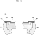
- FIG. 14 is a diagram illustrating an example section of a part of each of a first housing structure and a second housing structure according to an embodiment.
- FIG. 15 is a diagram illustrating an example section of a part of each of a first housing structure and a second housing structure when an electronic device according to an embodiment is in a folded state. According to an embodiment, FIG. 14 and FIG. 15 may illustrate a part of each of the first housing structure 310 and the second housing structure 320 illustrated in FIG. 7 and FIG. 8 .
- the conductive portion 1421 and the nonconductive portion 1422 of the second housing structure 1420 may be formed to be symmetric with the conductive portion 1411 and the nonconductive portion 1412 of the first housing structure 1410 with reference to the folding axis (axis A) (for example, the folding axis (A) of FIG. 5 ).
- the nonconductive portion 1412 of the first housing structure 1410 and the nonconductive portion 1422 of the second housing structure 1410 may be the low-permittivity material 710 illustrated in FIG. 7 and FIG. 8 .
- the nonconductive portion 1412 of the first housing structure 1410 may face or contact each other when the electronic device 1400 is in the folded state.
- the electronic device 1400 may reduce degradation of the antenna performance by spacing the conductive portion 1411 of the first housing structure 1410 and the conductive portion 1421 of the second housing structure 1420 apart from each other when the electronic device 1400 is in the folded state.
- the electronic device 1400 may reduce the phenomenon of coupling of energy radiated from the conductive portion 1411 of the first housing structure 1410 with the conductive portion 1421 of the second housing structure 1420.
- FIG. 16 is an exploded perspective view of an example electronic device including a frame according to various embodiments.
- the electronic device 1600 of FIG. 16 may be at least partially similar to the electronic devices illustrated in FIG. 2 to FIG. 11 .
- the electronic device 1600 may include: a foldable housing 1610 or 1620 (for example, the foldable housing 300 of FIG. 3 ), at least a part of which is folded using a hinge structure 1615 (for example, the hinge structure 340 of FIG. 4 ); a flexible display 1630 (for example, the display 200 of FIG. 2 ) loaded (e.g., disposed) on the foldable housing 1610 or 1620 such that at least a part thereof is configured to be folded; a frame 1640 loaded (e.g., disposed) on the boundary portions 1631 and 1632 of the flexible display 1630 or on at least a part of the boundary portions and coupled to the foldable housing 1610 or 1620.
- a foldable housing 1610 or 1620 for example, the foldable housing 300 of FIG. 3
- a hinge structure 1615 for example, the hinge structure 340 of FIG. 4
- a flexible display 1630 for example, the display 200 of FIG. 2
- a frame 1640 loaded (e.g., disposed) on the boundary portions 16
- the foldable housing 1610 or 1620 may include a first housing structure 1610 (for example, the first housing structure 310 of FIG. 2 ) disposed on one side of the hinge structure 1615 with reference to the hinge structure 1615, or a second housing structure 1620 (for example, the second housing structure 320 of FIG. 2 ) disposed on the other side of the hinge structure 1615.
- a first housing structure 1610 for example, the first housing structure 310 of FIG. 2
- a second housing structure 1620 for example, the second housing structure 320 of FIG. 2
- the foldable housing 1610 or 1620 may include a first side member 1611 (for example, the first side housing 343 of FIG. 2 ) surrounding a first space disposed on one side of the hinge structure 1615, and a second side member 1621 (for example, the second side housing 353 of FIG. 2 ) surrounding a second space disposed on the other side of the hinge structure 1615.
- a first side member 1611 for example, the first side housing 343 of FIG. 2
- a second side member 1621 for example, the second side housing 353 of FIG. 2
- the entire boundary portion of the front surface of the foldable housing 1610 or 1620 of the electronic device 1600 may include a low-permittivity material (for example, the low-permittivity materials 712, 731, and 732 of FIG. 7 ).
- the electronic device 1600 may include a frame 1640 disposed on the boundary portion of each of the first surface (for example, the first surface 341 of FIG. 2 ) and the third surface (for example, the third surface 351 of FIG. 2 ), which are configured to face each other in the folded state of the foldable housing 1610 or 1620, and the frame 1640 may include the low-permittivity material.
- the electronic device 1600 may have a first frame 1641 or a second frame 1642 disposed on the boundary portion of the flexible display 1630 in the unfolded state of the foldable housing 1610 or 1620, when the flexible display 1630 is viewed from above.
- the frame 1640 may be a component substantially identical or similar to the nonconductive portion 1412 and the nonconductive portion 1422 illustrated in FIG. 14 and FIG. 15 .
- the frame 1640 may include, for example, and without limitation, various decorative elements for aesthetic purposes.
- the frame 1640 may include a first frame 1641 overlapping the first housing structure 1610, or a second frame 1642 overlapping the second housing structure 1620.
- the first frame 1641 and the second frame 1642 may contact each other or approach each other such that the distance between thereof is equal to or less than a designated distance, in the folded state of the foldable housing 1610 or 1620.
- the first frame 1641 may be coupled to the first side member 1611 while covering a boundary portion of the flexible display 1630 such that the first boundary portion 1631 of the flexible display 1630 disposed on the first housing structure 1610, for example, the first non-display area thereof, is not exposed to the outside.
- the second frame 1642 may be coupled to the second side member 1621 while covering another boundary portion of the flexible display 1630 such that the second boundary portion 1632 of the flexible display 1630 disposed on the second housing structure 1620, for example, the second non-display area thereof, is not exposed to the outside.
- At least one sensor may be disposed on the outer periphery of the flexible display 1630, and a third frame 1643 including the low-permittivity material may be disposed on the boundary portion of a sensor area (for example, the sensor area 324 of FIG. 2 ) in which the sensor is disposed.
- the third frame 1643 may be formed integrally with the first frame 1641.
- the frame 1640 may include a low-permittivity material having a specific permittivity less than 10.
- the frame 1640 may include, for example, and without limitation, an injection-molded material.
- the frame 1640 may include a polymer material or a metal material, and may be coupled to respective housing structures 1610 or 1620 using at least one of bonding, taping, thermal attachment, or structural coupling.
- the electronic device may operate in an out-folding type unlike the examples illustrated in FIG. 2 to FIG. 11 .
- the second surface (for example, the second surface 342 of FIG. 2 ) and the fourth surface (for example, the fourth surface 352 of FIG. 2 ) of the electronic device may face each other in the folded state of the foldable housing.
- the electronic device according to various example embodiments may have structures including a low-permittivity material having a specific permittivity less than 10 and disposed on at least a part of the boundary portion of the second surface (for example, the second surface 342 of FIG. 2 ) and on at least a part of the boundary portion of the fourth surface (for example, the fourth surface 352 of FIG. 2 ), respectively.
- the electronic device, configured as above, may have reduced antenna performance degradation in the folded sate of the foldable housing.
- the electronic device may be one of various types of electronic devices.
- the electronic devices may include, for example, and without limitation, a portable communication device (e.g., a smartphone), a computer device, a portable multimedia device, a portable medical device, a camera, a wearable device, a home appliance, or the like. According to an embodiment of the disclosure, the electronic devices are not limited to those described above.
- each of such phrases as “A or B,” “at least one of A and B,” “at least one of A or B,” “A, B, or C,” “at least one of A, B, and C,” and “at least one of A, B, or C,” may include any one of, or all possible combinations of the items enumerated together in a corresponding one of the phrases.
- such terms as “1st” and “2nd,” or “first” and “second” may be used to simply distinguish a corresponding component from another, and does not limit the components in other aspect (e.g., importance or order).
- an element e.g., a first element
- the element may be coupled with the other element directly (e.g., wiredly), wirelessly, or via a third element.
- module may include a unit implemented in hardware, software, or firmware, and may interchangeably be used with other terms, for example, “logic,” “logic block,” “part,” or “circuitry”.
- a module may be a single integral component, or a minimum unit or part thereof, adapted to perform one or more functions.
- the module may be implemented in a form of an application-specific integrated circuit (ASIC).
- ASIC application-specific integrated circuit
- Various embodiments as set forth herein may be implemented as software (e.g., the program 140) including one or more instructions that are stored in a storage medium (e.g., internal memory 136 or external memory 138) that is readable by a machine (e.g., the electronic device 101) .
- a processor(e.g., the processor 120) of the machine e.g., the electronic device 101
- the one or more instructions may include a code generated by a complier or a code executable by an interpreter.
- the machine-readable storage medium may be provided in the form of a non-transitory storage medium.
- non-transitory simply refers to a storage medium that is a tangible device, but this term does not differentiate between where data is semi-permanently stored in the storage medium and where the data is temporarily stored in the storage medium.
- a method may be included and provided in a computer program product.
- the computer program product may be traded as a product between a seller and a buyer.
- the computer program product may be distributed in the form of a machine-readable storage medium (e.g., compact disc read only memory (CD-ROM)), or be distributed (e.g., downloaded or uploaded) online via an application store (e.g., PlayStore TM ), or between two user devices (e.g., smart phones) directly. If distributed online, at least part of the computer program product may be temporarily generated or at least temporarily stored in the machine-readable storage medium, such as memory of the manufacturer's server, a server of the application store, or a relay server.
- CD-ROM compact disc read only memory
- an application store e.g., PlayStore TM
- two user devices e.g., smart phones
- each component e.g., a module or a program of the above-described components may include a single entity or multiple entities. According to various embodiments, one or more of the above-described components may be omitted, or one or more other components may be added. Alternatively or additionally, a plurality of components (e.g., modules or programs) may be integrated into a single component. In such a case, according to various embodiments, the integrated component may still perform one or more functions of each of the plurality of components in the same or similar manner as they are performed by a corresponding one of the plurality of components before the integration.
- operations performed by the module, the program, or another component may be carried out sequentially, in parallel, repeatedly, or heuristically, or one or more of the operations may be executed in a different order or omitted, or one or more other operations may be added.
- An electronic device comprising:
- the foldable housing comprises a hinge, a first side member surrounding a first space disposed on a first side of the hinge, and a second side member surrounding a second space disposed on a second side of the hinge
- the frame comprises a first frame coupled to the first side member and covering a first boundary portion of the flexible display disposed on the first side of the hinge, and a second frame coupled to the second side member and covering a second boundary portion of the flexible display disposed on the second side of the hinge.
- Clause 4 The electronic device of clause 2, wherein, in a folded state of the foldable housing, the first frame and the second frame are configured to contact each other or to be within a distance of each other such that the distance between the first frame and the second frame is equal to or less than a designated distance.
- Clause 7 The electronic device of clause 2, wherein, in an unfolded state of the foldable housing, the first frame or the second frame is disposed on the boundary portion of the flexible display when the flexible display is viewed from above.
- Clause 8 The electronic device of clause 2, wherein the electronic device further comprises at least one sensor disposed on an outer periphery of the flexible display and exposed through a front surface of the electronic device to which the flexible display is exposed, and a third frame comprising the low-permittivity material is disposed on a boundary portion of a sensor area in which the at least one sensor is disposed, and wherein the third frame is integral with the first frame.
- Clause 9 The electronic device of clause 1, further comprising: a processor operatively connected to the communication circuit; and
- Clause 10 The electronic device of clause 9, wherein the communication function comprises a speech function.
- a foldable electronic device comprising:
- Clause 14 The foldable electronic device of clause 11, wherein the first side housing comprises a first side surface parallel to the folding axis, a second side surface connected to a first side of the first side surface, the second side surface being perpendicular to the folding axis, and a third side surface connected to a second side of the first side surface, the third side surface being parallel with the second side surface;
- Clause 15 The foldable electronic device of clause 14, wherein a corner portion of the first surface adjacent to the first side surface comprises a first protruding portion;
Landscapes
- Engineering & Computer Science (AREA)
- Computer Hardware Design (AREA)
- Theoretical Computer Science (AREA)
- General Engineering & Computer Science (AREA)
- Signal Processing (AREA)
- Physics & Mathematics (AREA)
- General Physics & Mathematics (AREA)
- Human Computer Interaction (AREA)
- Computer Networks & Wireless Communication (AREA)
- Mathematical Physics (AREA)
- Telephone Set Structure (AREA)
- Details Of Aerials (AREA)
- Support Of Aerials (AREA)
Applications Claiming Priority (4)
| Application Number | Priority Date | Filing Date | Title |
|---|---|---|---|
| KR20180093954 | 2018-08-10 | ||
| KR1020190094397A KR102746762B1 (ko) | 2018-08-10 | 2019-08-02 | 안테나를 포함하는 폴더블 전자 장치 |
| EP21197590.9A EP3944055B1 (fr) | 2018-08-10 | 2019-08-12 | Dispositif électronique pliable comprenant une antenne |
| EP19191295.5A EP3608751B1 (fr) | 2018-08-10 | 2019-08-12 | Dispositif électronique pliable comprenant une antenne integrée au cadre du boîtier |
Related Parent Applications (3)
| Application Number | Title | Priority Date | Filing Date |
|---|---|---|---|
| EP21197590.9A Division-Into EP3944055B1 (fr) | 2018-08-10 | 2019-08-12 | Dispositif électronique pliable comprenant une antenne |
| EP21197590.9A Division EP3944055B1 (fr) | 2018-08-10 | 2019-08-12 | Dispositif électronique pliable comprenant une antenne |
| EP19191295.5A Division EP3608751B1 (fr) | 2018-08-10 | 2019-08-12 | Dispositif électronique pliable comprenant une antenne integrée au cadre du boîtier |
Publications (2)
| Publication Number | Publication Date |
|---|---|
| EP4465543A2 true EP4465543A2 (fr) | 2024-11-20 |
| EP4465543A3 EP4465543A3 (fr) | 2025-02-26 |
Family
ID=69669913
Family Applications (2)
| Application Number | Title | Priority Date | Filing Date |
|---|---|---|---|
| EP21197590.9A Active EP3944055B1 (fr) | 2018-08-10 | 2019-08-12 | Dispositif électronique pliable comprenant une antenne |
| EP24203836.2A Pending EP4465543A3 (fr) | 2018-08-10 | 2019-08-12 | Dispositif électronique pliable comprenant une antenne |
Family Applications Before (1)
| Application Number | Title | Priority Date | Filing Date |
|---|---|---|---|
| EP21197590.9A Active EP3944055B1 (fr) | 2018-08-10 | 2019-08-12 | Dispositif électronique pliable comprenant une antenne |
Country Status (7)
| Country | Link |
|---|---|
| EP (2) | EP3944055B1 (fr) |
| KR (2) | KR102746762B1 (fr) |
| CN (2) | CN114793252B (fr) |
| AU (1) | AU2019318183B2 (fr) |
| ES (2) | ES2966802T3 (fr) |
| HU (2) | HUE069349T2 (fr) |
| PL (2) | PL3608751T3 (fr) |
Families Citing this family (28)
| Publication number | Priority date | Publication date | Assignee | Title |
|---|---|---|---|---|
| CN111416197B (zh) * | 2020-03-31 | 2021-08-17 | Oppo广东移动通信有限公司 | 可折叠壳体组件和可折叠电子设备 |
| KR102769071B1 (ko) | 2020-05-25 | 2025-02-18 | 삼성전자 주식회사 | 안테나를 포함하는 전자 장치 |
| KR102920644B1 (ko) * | 2020-06-19 | 2026-02-02 | 삼성전자주식회사 | 전자 장치 |
| KR102825916B1 (ko) | 2020-07-08 | 2025-06-30 | 삼성디스플레이 주식회사 | 전자 장치 |
| KR102825633B1 (ko) | 2020-07-31 | 2025-06-26 | 삼성전자주식회사 | 안테나 및 그것을 포함하는 전자 장치 |
| MY199608A (en) | 2020-07-31 | 2023-11-09 | Samsung Electronics Co Ltd | Electronic device including conductive member |
| KR20220052047A (ko) | 2020-10-20 | 2022-04-27 | 삼성전자주식회사 | 안테나 기반의 위치를 측정하는 방법 및 전자 장치 |
| KR102858143B1 (ko) * | 2020-10-28 | 2025-09-11 | 삼성전자주식회사 | 금속성 부재 및 안테나를 포함하는 전자 장치 |
| EP4191785A4 (fr) * | 2020-10-30 | 2024-01-24 | Samsung Electronics Co., Ltd. | Antenne et dispositif électronique la comprenant |
| CN112382843B (zh) * | 2020-11-03 | 2022-12-23 | 上海闻泰信息技术有限公司 | 天线及电子设备 |
| CN112382201A (zh) * | 2020-11-17 | 2021-02-19 | 武汉华星光电半导体显示技术有限公司 | 柔性屏折叠模组及显示装置 |
| KR102905385B1 (ko) | 2020-11-18 | 2025-12-30 | 삼성전자주식회사 | 플렉서블 디스플레이를 포함하는 폴더블 전자 장치 |
| WO2022108121A1 (fr) | 2020-11-18 | 2022-05-27 | 삼성전자 주식회사 | Dispositif électronique comprenant un écran enroulable |
| KR102888879B1 (ko) * | 2020-12-02 | 2025-11-21 | 삼성전자 주식회사 | 안테나를 포함하는 전자 장치 |
| KR102943083B1 (ko) * | 2021-02-10 | 2026-03-24 | 삼성전자 주식회사 | 도전성 부재를 포함하는 전자 장치 |
| KR20220140979A (ko) | 2021-04-12 | 2022-10-19 | 삼성전자주식회사 | 안정적인 전기적 연결을 위한 전자 장치 |
| KR20230021220A (ko) | 2021-08-04 | 2023-02-14 | 삼성디스플레이 주식회사 | 표시 장치 및 그것을 포함하는 전자 장치 |
| KR20230023507A (ko) | 2021-08-10 | 2023-02-17 | 삼성전자주식회사 | 유전체를 포함하는 디스플레이 구조 및 이를 포함하는 전자 장치 |
| KR20230066890A (ko) * | 2021-11-08 | 2023-05-16 | 삼성전자주식회사 | 안테나 구조 및 안테나 구조를 포함하는 전자 장치 |
| EP4354653A4 (fr) | 2021-11-08 | 2024-12-04 | Samsung Electronics Co., Ltd. | Structure d'antenne et dispositif électronique comprenant une structure d'antenne |
| WO2023195739A1 (fr) * | 2022-04-04 | 2023-10-12 | 삼성전자 주식회사 | Structure d'affichage et dispositif électronique comprenant une structure d'affichage |
| CN119585945A (zh) * | 2022-07-29 | 2025-03-07 | 三星电子株式会社 | 天线结构和包括该天线结构的电子装置 |
| CN115296013B (zh) * | 2022-08-04 | 2023-08-04 | 荣耀终端有限公司 | 一种天线组件和电子设备 |
| WO2024063621A1 (fr) * | 2022-09-23 | 2024-03-28 | 삼성전자주식회사 | Dispositif électronique comprenant une structure de connexion utilisée comme trajet de transmission de signal |
| EP4411510B1 (fr) * | 2022-12-13 | 2026-04-15 | Samsung Electronics Co., Ltd. | Dispositif électronique comprenant un élément conducteur |
| EP4625101A4 (fr) * | 2024-02-08 | 2026-04-08 | Samsung Electronics Co Ltd | Dispositif électronique comprenant une antenne et un boîtier pliable |
| WO2026010084A1 (fr) * | 2024-07-05 | 2026-01-08 | 삼성전자주식회사 | Dispositif électronique contenant une partie conductrice |
| WO2026079726A1 (fr) * | 2024-10-13 | 2026-04-16 | 삼성전자주식회사 | Dispositif électronique comprenant un boîtier |
Family Cites Families (14)
| Publication number | Priority date | Publication date | Assignee | Title |
|---|---|---|---|---|
| JP2002033805A (ja) | 2000-07-14 | 2002-01-31 | Matsushita Electric Ind Co Ltd | 携帯無線装置 |
| KR100592655B1 (ko) * | 2003-12-19 | 2006-06-23 | 주식회사 팬택 | 이동통신단말기의 쿠션장치 |
| JP2007053450A (ja) * | 2005-08-15 | 2007-03-01 | Nec Access Technica Ltd | 携帯通信端末 |
| KR101978956B1 (ko) * | 2012-07-27 | 2019-05-16 | 엘지전자 주식회사 | 이동 단말기 |
| KR102725441B1 (ko) * | 2013-08-30 | 2024-11-04 | 가부시키가이샤 한도오따이 에네루기 켄큐쇼 | 표시 장치 |
| US9513672B2 (en) | 2015-05-05 | 2016-12-06 | Apple Inc. | Electronic device with dynamic hinge gap cover |
| KR102364413B1 (ko) * | 2015-05-27 | 2022-02-17 | 삼성전자주식회사 | 안테나 장치를 포함하는 전자 장치 |
| US10727170B2 (en) * | 2015-09-01 | 2020-07-28 | Semiconductor Components Industries, Llc | Semiconductor devices and methods of making the same |
| BR112018009761B1 (pt) * | 2015-11-13 | 2023-05-02 | Samsung Electronics Co., Ltd | Dispositivo eletrônico |
| KR102164704B1 (ko) * | 2015-11-13 | 2020-10-12 | 삼성전자주식회사 | 금속 프레임 안테나를 구비한 전자 장치 |
| KR102396992B1 (ko) * | 2015-12-07 | 2022-05-12 | 삼성전자 주식회사 | 안테나를 포함하는 전자 장치 |
| KR102518499B1 (ko) * | 2016-04-22 | 2023-04-05 | 삼성전자주식회사 | 안테나 및 이를 포함하는 전자 장치 |
| KR102465796B1 (ko) * | 2016-05-27 | 2022-11-10 | 삼성전자주식회사 | 다중 슬롯 안테나를 가지는 전자 장치 |
| KR102553887B1 (ko) * | 2016-06-01 | 2023-07-11 | 삼성전자주식회사 | 폴더블 전자 장치 |
-
2019
- 2019-08-02 KR KR1020190094397A patent/KR102746762B1/ko active Active
- 2019-08-08 AU AU2019318183A patent/AU2019318183B2/en active Active
- 2019-08-09 CN CN202210266436.XA patent/CN114793252B/zh active Active
- 2019-08-09 CN CN201910737820.1A patent/CN110830618B/zh active Active
- 2019-08-12 PL PL19191295.5T patent/PL3608751T3/pl unknown
- 2019-08-12 EP EP21197590.9A patent/EP3944055B1/fr active Active
- 2019-08-12 PL PL21197590.9T patent/PL3944055T3/pl unknown
- 2019-08-12 HU HUE21197590A patent/HUE069349T2/hu unknown
- 2019-08-12 ES ES19191295T patent/ES2966802T3/es active Active
- 2019-08-12 ES ES21197590T patent/ES2997533T3/es active Active
- 2019-08-12 HU HUE19191295A patent/HUE065184T2/hu unknown
- 2019-08-12 EP EP24203836.2A patent/EP4465543A3/fr active Pending
-
2024
- 2024-12-20 KR KR1020240192200A patent/KR20250004199A/ko active Pending
Also Published As
| Publication number | Publication date |
|---|---|
| EP3944055B1 (fr) | 2024-11-06 |
| EP3944055C0 (fr) | 2024-11-06 |
| KR20250004199A (ko) | 2025-01-07 |
| CN114793252A (zh) | 2022-07-26 |
| PL3608751T3 (pl) | 2024-04-08 |
| ES2966802T3 (es) | 2024-04-24 |
| EP4465543A3 (fr) | 2025-02-26 |
| EP3944055A1 (fr) | 2022-01-26 |
| KR102746762B1 (ko) | 2024-12-27 |
| HUE065184T2 (hu) | 2024-05-28 |
| AU2019318183B2 (en) | 2022-01-13 |
| KR20200018282A (ko) | 2020-02-19 |
| CN110830618A (zh) | 2020-02-21 |
| CN110830618B (zh) | 2022-04-05 |
| HUE069349T2 (hu) | 2025-03-28 |
| PL3944055T3 (pl) | 2025-01-27 |
| ES2997533T3 (en) | 2025-02-17 |
| CN114793252B (zh) | 2025-09-12 |
| AU2019318183A1 (en) | 2021-02-25 |
Similar Documents
| Publication | Publication Date | Title |
|---|---|---|
| US11594157B2 (en) | Foldable electronic device including antenna | |
| AU2019318183B2 (en) | Foldable electronic device including antenna | |
| US11758673B2 (en) | Electronic device including antenna device | |
| EP3813343B1 (fr) | Dispositif électronique comprenant un affichage flexible et une antenne | |
| US11211961B2 (en) | Foldable electronic device including antenna | |
| CN113454844B (zh) | 多个天线和包括其的电子装置 | |
| EP3656113B1 (fr) | Dispositif électronique comprenant une antenne | |
| US20230051681A1 (en) | Electronic device comprising antenna | |
| US10833403B2 (en) | Antenna and electronic device including same | |
| CN112956179B (zh) | 包括天线的电子装置 | |
| US10944167B2 (en) | Electronic device that reduces antenna interference and enhances antenna performance | |
| EP3725064B1 (fr) | Structure d'antenne et dispositif électronique la comprenant | |
| US11824260B2 (en) | Electronic device comprising antenna | |
| KR102454823B1 (ko) | 메탈 커버를 안테나 방사체로 이용하는 전자 장치 | |
| KR102732953B1 (ko) | 폴더블 전자 장치 및 이를 위한 방법 | |
| US12225149B2 (en) | Electronic device comprising antenna | |
| US11563280B2 (en) | Electronic device including antenna | |
| US12051851B2 (en) | Electronic device including antenna including coupling-feeding structure |
Legal Events
| Date | Code | Title | Description |
|---|---|---|---|
| PUAI | Public reference made under article 153(3) epc to a published international application that has entered the european phase |
Free format text: ORIGINAL CODE: 0009012 |
|
| STAA | Information on the status of an ep patent application or granted ep patent |
Free format text: STATUS: THE APPLICATION HAS BEEN PUBLISHED |
|
| AC | Divisional application: reference to earlier application |
Ref document number: 3608751 Country of ref document: EP Kind code of ref document: P Ref document number: 3944055 Country of ref document: EP Kind code of ref document: P |
|
| AK | Designated contracting states |
Kind code of ref document: A2 Designated state(s): AL AT BE BG CH CY CZ DE DK EE ES FI FR GB GR HR HU IE IS IT LI LT LU LV MC MK MT NL NO PL PT RO RS SE SI SK SM TR |
|
| REG | Reference to a national code |
Ref country code: DE Ref legal event code: R079 Free format text: PREVIOUS MAIN CLASS: H04B0001388800 Ipc: G06F0001160000 |
|
| PUAL | Search report despatched |
Free format text: ORIGINAL CODE: 0009013 |
|
| AK | Designated contracting states |
Kind code of ref document: A3 Designated state(s): AL AT BE BG CH CY CZ DE DK EE ES FI FR GB GR HR HU IE IS IT LI LT LU LV MC MK MT NL NO PL PT RO RS SE SI SK SM TR |
|
| RIC1 | Information provided on ipc code assigned before grant |
Ipc: H01Q 9/42 20060101ALI20250117BHEP Ipc: H04B 1/3888 20150101ALI20250117BHEP Ipc: H04M 1/02 20060101ALI20250117BHEP Ipc: H01Q 21/30 20060101ALI20250117BHEP Ipc: H01Q 1/24 20060101ALI20250117BHEP Ipc: G06F 1/16 20060101AFI20250117BHEP |
|
| STAA | Information on the status of an ep patent application or granted ep patent |
Free format text: STATUS: REQUEST FOR EXAMINATION WAS MADE |
|
| 17P | Request for examination filed |
Effective date: 20250721 |