EP4465615A1 - Kommunikationsverfahren und vorrichtung für edge-computing-system - Google Patents
Kommunikationsverfahren und vorrichtung für edge-computing-system Download PDFInfo
- Publication number
- EP4465615A1 EP4465615A1 EP23747400.2A EP23747400A EP4465615A1 EP 4465615 A1 EP4465615 A1 EP 4465615A1 EP 23747400 A EP23747400 A EP 23747400A EP 4465615 A1 EP4465615 A1 EP 4465615A1
- Authority
- EP
- European Patent Office
- Prior art keywords
- ees
- application context
- target
- eas
- application
- Prior art date
- Legal status (The legal status is an assumption and is not a legal conclusion. Google has not performed a legal analysis and makes no representation as to the accuracy of the status listed.)
- Pending
Links
Images


Classifications
-
- H—ELECTRICITY
- H04—ELECTRIC COMMUNICATION TECHNIQUE
- H04L—TRANSMISSION OF DIGITAL INFORMATION, e.g. TELEGRAPHIC COMMUNICATION
- H04L67/00—Network arrangements or protocols for supporting network services or applications
- H04L67/50—Network services
- H04L67/52—Network services specially adapted for the location of the user terminal
-
- H—ELECTRICITY
- H04—ELECTRIC COMMUNICATION TECHNIQUE
- H04L—TRANSMISSION OF DIGITAL INFORMATION, e.g. TELEGRAPHIC COMMUNICATION
- H04L67/00—Network arrangements or protocols for supporting network services or applications
- H04L67/14—Session management
- H04L67/148—Migration or transfer of sessions
-
- H—ELECTRICITY
- H04—ELECTRIC COMMUNICATION TECHNIQUE
- H04L—TRANSMISSION OF DIGITAL INFORMATION, e.g. TELEGRAPHIC COMMUNICATION
- H04L67/00—Network arrangements or protocols for supporting network services or applications
- H04L67/01—Protocols
- H04L67/10—Protocols in which an application is distributed across nodes in the network
-
- H—ELECTRICITY
- H04—ELECTRIC COMMUNICATION TECHNIQUE
- H04L—TRANSMISSION OF DIGITAL INFORMATION, e.g. TELEGRAPHIC COMMUNICATION
- H04L67/00—Network arrangements or protocols for supporting network services or applications
- H04L67/14—Session management
- H04L67/146—Markers for unambiguous identification of a particular session, e.g. session cookie or URL-encoding
-
- H—ELECTRICITY
- H04—ELECTRIC COMMUNICATION TECHNIQUE
- H04L—TRANSMISSION OF DIGITAL INFORMATION, e.g. TELEGRAPHIC COMMUNICATION
- H04L67/00—Network arrangements or protocols for supporting network services or applications
- H04L67/2866—Architectures; Arrangements
- H04L67/289—Intermediate processing functionally located close to the data consumer application, e.g. in same machine, in same home or in same sub-network
-
- H—ELECTRICITY
- H04—ELECTRIC COMMUNICATION TECHNIQUE
- H04L—TRANSMISSION OF DIGITAL INFORMATION, e.g. TELEGRAPHIC COMMUNICATION
- H04L67/00—Network arrangements or protocols for supporting network services or applications
- H04L67/50—Network services
- H04L67/51—Discovery or management thereof, e.g. service location protocol [SLP] or web services
-
- H—ELECTRICITY
- H04—ELECTRIC COMMUNICATION TECHNIQUE
- H04L—TRANSMISSION OF DIGITAL INFORMATION, e.g. TELEGRAPHIC COMMUNICATION
- H04L67/00—Network arrangements or protocols for supporting network services or applications
- H04L67/50—Network services
- H04L67/60—Scheduling or organising the servicing of application requests, e.g. requests for application data transmissions using the analysis and optimisation of the required network resources
- H04L67/62—Establishing a time schedule for servicing the requests
-
- H—ELECTRICITY
- H04—ELECTRIC COMMUNICATION TECHNIQUE
- H04L—TRANSMISSION OF DIGITAL INFORMATION, e.g. TELEGRAPHIC COMMUNICATION
- H04L67/00—Network arrangements or protocols for supporting network services or applications
- H04L67/50—Network services
- H04L67/60—Scheduling or organising the servicing of application requests, e.g. requests for application data transmissions using the analysis and optimisation of the required network resources
- H04L67/63—Routing a service request depending on the request content or context
-
- H—ELECTRICITY
- H04—ELECTRIC COMMUNICATION TECHNIQUE
- H04W—WIRELESS COMMUNICATION NETWORKS
- H04W36/00—Hand-off or reselection arrangements
- H04W36/0005—Control or signalling for completing the hand-off
- H04W36/0011—Control or signalling for completing the hand-off for data sessions of end-to-end connection
- H04W36/0033—Control or signalling for completing the hand-off for data sessions of end-to-end connection with transfer of context information
-
- H—ELECTRICITY
- H04—ELECTRIC COMMUNICATION TECHNIQUE
- H04W—WIRELESS COMMUNICATION NETWORKS
- H04W36/00—Hand-off or reselection arrangements
- H04W36/24—Reselection being triggered by specific parameters
- H04W36/32—Reselection being triggered by specific parameters by location or mobility data, e.g. speed data
-
- H—ELECTRICITY
- H04—ELECTRIC COMMUNICATION TECHNIQUE
- H04W—WIRELESS COMMUNICATION NETWORKS
- H04W36/00—Hand-off or reselection arrangements
- H04W36/24—Reselection being triggered by specific parameters
- H04W36/32—Reselection being triggered by specific parameters by location or mobility data, e.g. speed data
- H04W36/322—Reselection being triggered by specific parameters by location or mobility data, e.g. speed data by location data
-
- H—ELECTRICITY
- H04—ELECTRIC COMMUNICATION TECHNIQUE
- H04W—WIRELESS COMMUNICATION NETWORKS
- H04W4/00—Services specially adapted for wireless communication networks; Facilities therefor
- H04W4/02—Services making use of location information
- H04W4/029—Location-based management or tracking services
-
- H—ELECTRICITY
- H04—ELECTRIC COMMUNICATION TECHNIQUE
- H04W—WIRELESS COMMUNICATION NETWORKS
- H04W4/00—Services specially adapted for wireless communication networks; Facilities therefor
- H04W4/02—Services making use of location information
-
- H—ELECTRICITY
- H04—ELECTRIC COMMUNICATION TECHNIQUE
- H04W—WIRELESS COMMUNICATION NETWORKS
- H04W64/00—Locating users or terminals or network equipment for network management purposes, e.g. mobility management
Definitions
- the disclosure relates to a method and device for performing communication between a UE and a network server in an edge computing system.
- 5G mobile communication technologies define broad frequency bands such that high transmission rates and new services are possible, and can be implemented not only in “Sub 6GHz” bands such as 3.5GHz, but also in “Above 6GHz” bands referred to as mmWave including 28GHz and 39GHz.
- 6G mobile communication technologies referred to as Beyond 5G systems
- terahertz bands for example, 95GHz to 3THz bands
- IIoT Industrial Internet of Things
- IAB Integrated Access and Backhaul
- DAPS Dual Active Protocol Stack
- 5G baseline architecture for example, service based architecture or service based interface
- NFV Network Functions Virtualization
- SDN Software-Defined Networking
- MEC Mobile Edge Computing
- multi-antenna transmission technologies such as Full Dimensional MIMO (FD-MIMO), array antennas and large-scale antennas, metamaterial-based lenses and antennas for improving coverage of terahertz band signals, high-dimensional space multiplexing technology using OAM (Orbital Angular Momentum), and RIS (Reconfigurable Intelligent Surface), but also full-duplex technology for increasing frequency efficiency of 6G mobile communication technologies and improving system networks, AI-based communication technology for implementing system optimization by utilizing satellites and AI (Artificial Intelligence) from the design stage and internalizing end-to-end AI support functions, and next-generation distributed computing technology for implementing services at levels of complexity exceeding the limit of UE operation capability by utilizing ultra-high-performance communication and computing resources.
- FD-MIMO Full Dimensional MIMO
- OAM Organic Angular Momentum
- RIS Reconfigurable Intelligent Surface
- An aspect of the disclosure is to provide a method and device for performing communication between a UE and a server in an edge computing system.
- Another aspect of the disclosure is to provide a method and device for effectively managing application context information between a UE and a server.
- Another aspect of the disclosure is to efficiently change an edge enabler server or an edge application server according to a movement of a UE.
- an edge enabler server (EES) in a wireless communication system may comprise a transceiver and at least one processor connected to the transceiver.
- the at least one processor may be configured to: receive, from an edge enabler client (EEC) a request message including information related to a predicted movement path of a user equipment (UE) in which the EEC is included, and determine an application context storage time based on the information related to the predicted movement path of the UE.
- EEC edge enabler client
- UE user equipment
- the request message may be an application context relocation (ACR) request message.
- the information related to the predicted movement path of the UE may include at least one of a service continuity planning indication, a target EES service area predicted arrival time, an application context holding timer request value (application context expiration timer), an identifier of the UE, an application identifier, information about an EES currently serving the UE, and an edge application server (EAS) currently serving the UE.
- ACR application context relocation
- the at least one processor may determine a first edge application server (EAS) based on the movement path of the UE, receive, from the first EAS, information related to a predetermined application context storable time and determine the application context storage time based on the information related to the application context storable time and the information related to the predicted movement path of the UE.
- EAS edge application server
- the application context storage time may be determined to be a smaller value of the application context storable time and the information related to the predicted movement path of the UE.
- the at least one processor may be further configured to transmit the determined application context storage time to the EEC.
- a method performed by an edge enabler server (EES) in a wireless communication system may comprise receiving a request message including information related to a predicted movement path of a user equipment (UE) including an edge enabler client (EEC) from the EEC and determining an application context storage time based on the information related to the predicted movement path of the UE.
- UE user equipment
- EEC edge enabler client
- the UE may transmit the application context information to the peripheral edge application server in advance from the edge application server currently being serviced, and the peripheral edge application server may store the application context information.
- the mobility prediction for the UE is wrong, there is a need for a device for deleting the application context stored in the peripheral edge application server and recovering related resources.
- each flowchart and combinations of the flowcharts may be performed by computer program instructions. Since the computer program instructions may be equipped in a processor of a general-use computer, a special-use computer or other programmable data processing devices, the instructions executed through a processor of a computer or other programmable data processing devices generate means for performing the functions described in connection with a block(s) of each flowchart.
- the computer program instructions may be stored in a computer-available or computer-readable memory that may be oriented to a computer or other programmable data processing devices to implement a function in a specified manner, the instructions stored in the computer-available or computer-readable memory may produce a product including an instruction means for performing the functions described in connection with a block(s) in each flowchart. Since the computer program instructions may be equipped in a computer or other programmable data processing devices, instructions that generate a process executed by a computer as a series of operational steps are performed over the computer or other programmable data processing devices and operate the computer or other programmable data processing devices may provide steps for executing the functions described in connection with a block(s) in each flowchart.
- each block may represent a module, segment, or part of a code including one or more executable instructions for executing a specified logical function(s).
- the functions mentioned in the blocks may occur in different orders. For example, two blocks that are consecutively shown may be performed substantially simultaneously or in a reverse order depending on corresponding functions.
- a unit means a software element or a hardware element such as a field-programmable gate array (FPGA) or an application specific integrated circuit (ASIC).
- FPGA field-programmable gate array
- ASIC application specific integrated circuit
- a unit plays a certain role.
- 'unit' is not limited to software or hardware.
- a 'unit' may be configured in a storage medium that may be addressed or may be configured to execute one or more processors. Accordingly, as an example, a 'unit' includes elements, such as software elements, object-oriented software elements, class elements, and task elements, processes, functions, attributes, procedures, subroutines, segments of program codes, drivers, firmware, microcodes, circuits, data, databases, data architectures, tables, arrays, and variables.
- a "...unit" may include one or more processors.
- 3GPP 3rd generation partnership project
- NR 5th generation mobile communication standards
- the embodiments of the disclosure may also apply to other communication systems with similar technical background or channel form.
- embodiments of the present invention may be modified in such a range as not to significantly depart from the scope of the present invention under the determination by one of ordinary skill in the art and such modifications may be applicable to other communication systems.
- first and second may be used to describe various components, but the components should not be limited by the terms. The terms are used only to distinguish one component from another.
- the disclosure proposes a method for efficiently performing prediction-based edge application context relocation to support service persistence in an edge computing system.
- the EES proposes various methods for determining a period for storing the application context transmitted from the target EAS in the prediction-based application context relocation operation.
- methods for comprehensively using in a single procedure are also included in the scope of the disclosure.
- the target EES and the target EAS may determine an application context holding time value considering all of (1) the predicted movement path of the UE provided by the EEC or the predicted arrival time of the target EES or target EAS service area or the application context holding timer request value, (2) the storage space information available to the target EAS (information obtainable from inside of the target EAS or from the EAS management system), (3) the application context holding time considering the application context holding limit value set by the target EAS, and (4) the expected UE behavior information obtained through the network function of the 5G core network.
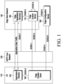
- FIG. 1 illustrates an example of a hierarchical structure between a UE and a communication network in an edge computing network.
- the edge computing system may include a user equipment (UE) 110, a communication network 120, an edge data network 130, and an edge configuration server 180.
- the UE 110 may include an application client 140 and an edge enabler client (EEC) 150.
- Edge data network 130 may be the concept encompassing all of edge enabler server (EES) 170 and edge application server (EAS) 160.
- the system related to edge computing may include an edge enabler server (EES) 170, an edge configuration server (ECS) 180, and an edge enabler client (EEC) 150.
- the edge enabler server 170 is establishing an edge hosting environment (or edge computing platform) and may know information about the edge application server (EAS) 160 running in the edge hosting environment.
- the edge enabler server 170 communicates with the UE 110 to connect the application client 140 of the UE 110 to the edge application server 160 in the edge hosting environment.
- the UE 110 supporting the edge computing system may include the edge enabler client 150.
- the layer that interworks with the edge enabler client 150 and the edge enabler server 170 may be referred to as an edge enabling layer.
- the UE 110 in which the edge enabler client 150 is embedded to configure the edge enabling layer may be an IoT device, a vehicle, or the like, as well as a smartphone.
- the edge configuration server 180 knows deployment information about the edge enabler servers 170 and performs a function of transferring configuration information for using the edge computing service to the UE 110.
- the configuration information may include edge data network connection information (e.g., data network name, single network slice selection assistance information (S-NSSAI), etc.), edge data network service area (e.g., cell list, list of tracking area, public land mobile network (PLMN) ID), edge enabler server connection information (e.g., URI).
- the edge data network service area may be an edge enabler server available area set by the edge enabler server 170. Based on this, the UE 110 may receive information about the edge enabler server 170 accessible at a specific location.
- the edge configuration server 180 may know information about the edge application server 160 running in the edge hosting environment of the specific edge enabler server 170, the UE 110 may also obtain the corresponding information through the edge enabler client 150.
- the layer where interworking between the edge enabler client 150 and the edge configuration server 180 is performed is also included in the edge enabling layer.
- the edge application server 160 refers to a third party application server driven in the edge computing system. Since the edge application server 160 is driven within an infrastructure provided by the edge hosting environment, the edge application server 160 may provide an ultra-low latency service at a location close to the UE 110.
- the application client 140 there may be an application client 140, an edge enabler client 150 for interworking the application client with the edge computing service, and a mobile terminal (MT) (not shown) accessing the mobile communication system.
- the application of the UE is an application provided by a third party and refers to a client application program driven in the UE for a specific application service.
- a plurality of applications may be driven in the UE 110. At least one of these applications may use a mobile edge computing or multi-access edge computing (MEC) service.
- the edge enabler client 150 in the UE refers to a client that performs an operation in the UE necessary for using the edge computing service.
- the operations for determining which application may use the edge computing service, and connecting the network interface so that data of the UE application client 140 may be transferred to the edge application server 160 providing the edge computing service may be performed.
- the operation for establishing a data connection for using the edge computing service may be performed by the 3GPP communication layer through the mobile terminal.
- the 3GPP communication layer refers to a layer that performs a modem operation for using a mobile communication system, and may serve to establish a wireless connection for data communication, register the UE in the mobile communication system, establish a connection for data transmission in the mobile communication system, and transmit and receive data.
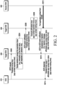
- FIG. 2 is a view illustrating a procedure for managing an application context based on an expected arrival time of a UE in an edge computing network, according to an embodiment of the disclosure.
- the EEC 210 may select the target EES and the target EAS using edge computing configuration information stored in the EEC 210 or edge computing configuration information obtained by requesting the edge configuration server (ECS) before performing step 1 of FIG. 2 . Based on this, the following operations may be performed.
- the EEC (or UE) 210 may directly calculate or obtain the predicted movement path of the UE and the predicted arrival time of the target EES or target EAS service area.
- the EEC 210 may select the target EES 220 in the predicted movement path of the UE.
- the EEC 210 may transmit an application context relocation (ACR) request message to the target EES 220 on the selected predicted movement path.
- ACR application context relocation
- the ACR request message may include at least one of ACR type information (an indicator indicating that the ACR request is prediction-based, e.g., a service continuity planning indication), target EES (or target EAS) service area predicted arrival time, an application context holding (expiration) timer request value, a UE identifier, an application identifier, source EES information (the address and identifier of the EES where the UE is currently connected or registered, the edge computing service provider identifier or source EES provider identifier as the source EES provider information), and the source EAS information (the identifier and the address of the edge application server currently serving the UE).
- ACR type information an indicator indicating that the ACR request is prediction-based, e.g., a service continuity planning indication
- target EES or target EAS service area predicted arrival time
- an application context holding (expiration) timer request value e.g., a UE identifier
- source EES information the address and identifier of the EES where the UE
- step S204 when the ACR request message received from the EEC 210 includes at least one of the indicator indicating that the ACR request is prediction-based, UE expected movement path information, or target EES (or target EAS) service area predicted arrival time information, the target EES 220 may review and recalculate whether to accept the ACR request which is prediction-based, the expected movement path of the UE provided by the EEC 210, and the target EES (or target EAS) service area predicted arrival time information. Such review and recalculation may be performed through various methods, and FIG. 2 relates to a method of performing a review and determining the prediction time by the target EES 220 in association with the target EAS 230.
- the target EES 220 may determine whether to perform the prediction-based application context relocation procedure according to the edge computing service provider policy or internal settings providing the target EES 220. For example, in the edge computing service provider policy or the internal settings, a policy forbidding the use of additional resources to pre-store the application context generated by the service provided by another provider may be set.
- the target EES 220 may provide the target EAS 230 with information received from the EEC 210 in step S202.
- the corresponding information may include at least one of ACR type information (an indicator indicating that the corresponding ACR request is prediction-based, e.g., the service continuity planning indication), the target EES (or target EAS) service area predicted arrival time, the application context holding timer request value, the UE identifier, the application identifier, and source EAS information (the identifier and address of the edge application server currently serving the UE).
- ACR type information an indicator indicating that the corresponding ACR request is prediction-based, e.g., the service continuity planning indication
- the target EES (or target EAS) service area predicted arrival time the application context holding timer request value
- the UE identifier the application context holding timer request value
- the UE identifier the application context holding timer request value
- source EAS information the identifier and address of the edge application server currently serving the UE.
- the target EAS 230 may determine whether it is possible to store and maintain the application context received from the source EAS 240 by the target EES (or target EAS) service area predicted arrival time received from the target EES 220 or the period specified in the application context holding timer request value ti.
- the target EAS 230 may obtain available storage space information from the EAS management system to determine the application context storage holdable time value t 2 .
- the EAS may directly obtain information about the available storage space, the EAS itself may calculate the application context storage holdable time value t 2 .
- the target EAS 230 may store the calculated final application context holding time value t h and, immediately after receiving the application context from the source EAS 240, drive the timer in which the corresponding time value is set to store the application context only during the set timer value period, and may wait for the corresponding UE to access.
- the target EAS 230 may transmit an acknowledgment message to the target EES 220 in response to the message received from the target EES 220 through step S206.
- the final application context holding time value t h determined in step S208 may be included in the corresponding acknowledgment message.
- the target EAS 230 may include a rejection indicator indicating rejection of the request in the corresponding response message. If the determined final application context holding time value t h is larger than or equal to the value ti received from the target EES 220 in step S206, the target EAS 230 may include an acceptance indicator indicating acceptance of the request in the corresponding acknowledgment message.
- the target EAS 230 may receive the message including the target EES (or target EAS) service area predicted arrival time or the application context holding timer request value ti from the target EES 220. Upon receiving the message, the target EAS 230 may calculate an application context storage holdable time value t 2 determined according to the available storage space, include the same in the acknowledgment message, and transmit the acknowledgment message to the target EES 220.
- the target EES 220 may compare the target EES (or target EAS) service area predicted arrival time or the application context holding timer request value ti with the application context storage holdable time value t 2 to determine the final application context holding time value t h .
- the same method as the method described in step S208 may be applied to the method of calculating the final application context holding time value t h .
- the determined final application context holding time value may be transmitted to the target EAS 230 and the EEC 210.
- the target EAS 230 may receive the application context for the service of the corresponding UE (the corresponding EEC) 210 from the source EAS 240 identified from the target EES 220 (pull operation). In this step, the target EAS 230 may inform the source EAS 240 that the pull operation is prediction-based application context relocation (or service continuity planning).
- the target EES 220 may transmit, to the EEC 210, a message including a result included in the response message received from the target EAS 230 in step S210 or a result calculated and determined by itself.
- the corresponding message may be a response message to the ACR request received from the EEC in step S202.
- the response message may include the final application context holding time value t h . For example, when the final application context holding time value t h provided from the target EES 220 is less than the application context holding timer request value ti presented in step S202, the EEC 210 may determine whether to continue or stop the application context relocation procedure for the target EES 220.
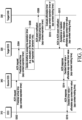
- FIG. 3 is a view illustrating a procedure for managing an application context based on an expected arrival time of a UE in an edge computing network, according to another embodiment of the disclosure.
- the source EES 340 may select the target EES 320 using edge computing configuration information stored in the source EES 340 before performing step S304 of FIG. 3 or edge computing configuration information obtained by requesting an edge configuration server (ECS). Based on this, the following operations may be performed.
- ECS edge configuration server
- the EEC 310 may transmit the ACR request message to the source EES 340.
- the ACR request message may include the predicted movement path of the UE calculated by the EEC 310 or obtained from another device in the UE, and the predicted arrival time to an EES service area other than the source EES or the source EES (or source EAS) service area exit time.
- the corresponding ACR request message may include at least one of ACR type information (an indicator indicating that the corresponding ACR request is prediction-based, e.g., the service continuity planning indication), the target EES (or target EAS) service area predicted arrival time, the application context holding timer request value, the UE identifier, the application identifier, and source EAS information (the identifier and address of the edge application server currently serving the UE).
- ACR type information an indicator indicating that the corresponding ACR request is prediction-based, e.g., the service continuity planning indication
- the target EES (or target EAS) service area predicted arrival time the application context holding timer request value
- the UE identifier the application context holding timer request value
- the UE identifier the application context holding timer request value
- source EAS information the identifier and address of the edge application server currently serving the UE.
- the source EES 340 may receive, from the EEC 310, the UE predicted movement path and the predicted arrival time to the EES service area other than the source EES currently connected or the source EES (or source EAS) service exit time and, based thereon, select the target EES 320 in the predicted movement path of the UE.
- the source EES 340 may transmit the application context relocation (ACR) request message to the target EES 320 on the selected predicted movement path.
- ACR application context relocation
- the corresponding ACR request message may include at least one of ACR type information (an indicator indicating that the corresponding ACR request is prediction-based, e.g., the service continuity planning indication), the target EES (or target EAS) service area predicted arrival time, the application context holding timer request value, the UE identifier, the application identifier, source EES information (the address and identifier of the EES in which the UE is currently connected or registered) and source EAS information (the identifier and address of the edge application server currently serving the UE).
- ACR type information an indicator indicating that the corresponding ACR request is prediction-based, e.g., the service continuity planning indication
- the target EES (or target EAS) service area predicted arrival time e.g., the application context holding timer request value
- the UE identifier e.g., the application context holding timer request value
- source EES information the address and identifier of the EES in which the UE is currently connected or registered
- source EAS information the identifie
- step S306 when the ACR request message received from the source EES 340 includes at least one of the indicator indicating that the ACR request is prediction-based, UE expected movement path information, or target EES service area predicted arrival time information, the EES 310 may review and recalculate whether to accept the corresponding prediction-based ACR request, the expected movement path of the UE provided by the source EES 340, and the target EES (or target EAS) service area predicted arrival time information.
- Such review and recalculation may be performed through various methods, and FIG. 3 relates to a method of performing a review and determining the prediction time by the target EES 320 in association with the target EAS 330.
- the target EES 320 may provide the target EAS 330 with information received from the EEC 310 in step S302.
- the corresponding information may include at least one of ACR type information (an indicator indicating that the corresponding ACR request is prediction-based, e.g., the service continuity planning indication), the target EES (or target EAS) service area predicted arrival time, the application context holding timer request value, the UE identifier, the application identifier, and source EAS information (the identifier and address of the edge application server currently serving the UE).
- ACR type information an indicator indicating that the corresponding ACR request is prediction-based, e.g., the service continuity planning indication
- the target EES (or target EAS) service area predicted arrival time the application context holding timer request value
- the UE identifier the application context holding timer request value
- the UE identifier the application context holding timer request value
- source EAS information the identifier and address of the edge application server currently serving the UE.
- the target EAS 330 may determine whether it is possible to store and maintain the application context received from the source EAS 340 by the target EES (or target EAS) service area predicted arrival time received from the target EES 320 via the source EES 340 in the EEC 310 or the period specified in the application context holding timer request value ti.
- the target EAS 330 may obtain available storage space information from the EAS management system to determine the application context storage holdable time value t 2 . Alternatively, when the EAS may directly obtain information about the available storage space, the corresponding value may be calculated. The target EAS 330 may store the calculated final application context holding time value t h and, immediately after receiving the application context from the source EAS 340, drive the timer in which the corresponding time value is set to store the application context only during the set timer value period, and may wait for the corresponding UE to access.
- the target EAS 330 transmits an acknowledgement message to the target EES 320 in response to the message received from the target EES 320 through step S308.
- the final application context holding time value determined in step S310 may be included in the corresponding acknowledgement message.
- the target EAS 330 may include a rejection indicator indicating rejection of the request in the corresponding response message. If the determined final application context holding time value t h is larger than or equal to the value ti received from the target EES 320 in step S308, the target EAS 330 may include an acceptance indicator indicating acceptance of the request in the corresponding acknowledgment message.
- the target EAS 330 may receive the message including the target EES (or target EAS) service area predicted arrival time or the application context holding timer request value ti from the target EES 320. Upon receiving the message, the target EAS 330 may calculate an application context storage holdable time value t 2 determined according to the available storage space, include the same in the acknowledgment message, and transmit the acknowledgment message to the target EES 320.
- the target EES 320 may compare the target EES (or target EAS) service area predicted arrival time or the application context holding timer request value ti with the application context storage holdable time value t 2 to determine the final application context holding time value t h .
- the same method as the method described in step S310 may be applied to the method of calculating the final application context holding time value t h .
- the target EES 330 may transmit, to the source EES 340, a message including a result included in the acknowledgment message received from the target EAS 330 in step S210 or a result calculated and determined by itself.
- the corresponding message may be a response message to the ACR request received from the source EES 340 in step S304.
- the response message may include the final application context holding time value t h . For example, when the final application context holding time value t h provided from the target EES 320 is less than the application context holding timer request value ti presented in step S304, the source EES 340 may determine whether to continue or stop the application context relocation procedure for the target EES 320.
- the source EES 340 may include the information obtained from the target EES 320 and the target EAS 330 in step S314 in the response message to the request message of step S302 and transmit the same to the EEC 310. For example, when the final application context holding time value t h provided from the target EES 320 is less than the application context holding timer request value ti presented in step S304, the EEC 310 may determine whether to continue or stop the application context relocation procedure for the target EES 320.
- FIG. 4 is a view illustrating a procedure for managing an application context based on an expected threshold time of an application server in an edge computing network, according to an embodiment of the disclosure.
- the target EES 420 may review and recalculate whether to accept the corresponding ACR request, the expected movement path of the UE provided by the EEC 410, and the target EES (or target EAS) service area predicted arrival time information. Such review and recalculation may be performed through various methods, and FIG. 4 relates to a method of performing a corresponding operation based on the information previously received from the target EAS by the target EES.
- the EAS may determine an application context holding limit value indicating how long the application context received from the source EAS is stored.
- the EAS management system may be determined according to the set value while instantiating the EAS, or may be determined according to the policy of the edge computing service provider that provides the hosting environment of the edge data network in which the EAS is instantiated.
- the application context holding limit value determined through these various methods may be used to process the ACR request message transmitted to the target EES 420 and transmitted from the EEC 410 or the source EAS.
- the target EAS 430 may determine and transmit the application context holding limit value (t th : application context timer threshold value) to the target EES 420.
- the application context holding limit value t th may be a timer value indicating how long the target EAS 430 will store the application context received from the source EAS in the target EAS 430 when the prediction-based application context relocation occurs.
- the information may be included in an EAS registration request message or an ACR management event subscription request message and be transmitted.
- the target EAS 430 may provide the application context holding limit value only when the prediction-based application context relocation is allowed. Further, the target EAS 430 may preset a validity period (timer validity) for the application context holding limit value and provide the preset timer validity to the target EES 420.
- the update of the validity period may be additionally performed through an EAS registration update procedure or an ACR management event subscription update procedure.
- the target EES 420 transmits, to the target EAS 430, a response message indicating that the application context holding limit value t th received from the target EAS 430 has been successfully set.
- the corresponding message has the form of a response message according to the message transmitted by the target EAS 430 in step S404.
- the response message is a response message to the EAS registration request
- information indicating the successful setting of the application context holding limit value may be transmitted together with the EAS registration identifier.
- the response message is a response message to the ACR management event subscription request message
- information indicating the successful setting of the application context holding limit value together with the subscription correlation ID may be transmitted to the target EAS 430.
- the target EES 420 may store the received application context holding limit value for the validity period.
- the target EES 420 may receive a prediction-based ACR request message from the EEC 410 (or source EES or source EAS).
- the ACR request message may include at least one of ACR type information (an indicator indicating that the corresponding ACR request is prediction-based, e.g., the service continuity planning indication), the target EES (or target EAS) service area predicted arrival time, the application context holding timer request value, the UE identifier, the application identifier, source EES information (the address and identifier of the EES in which the UE is currently connected or registered) and source EAS information (the identifier and address of the edge application server currently serving the UE).
- the target EES 420 may compare the received target EES (or target EAS) service area predicted arrival time or application context holding timer request value ti with the application context holding limit value t th set through the previous steps to determine a final application context holding time value t h (app context expiration timer or app context holding timer).
- the target EES 420 may provide the final application context holding time value t h determined in step S410 to the target EAS 430.
- the final application context holding time value t h may be provided together with information about the source EAS.
- the newly set final application context holding time value t h may be transmitted to the target EAS 430.
- whether to use t h which is a timer value smaller than the application context holding limit value t th , may be determined according to internal settings of the target EAS 430 or the like.
- the target EAS 430 may store the timer value determined to be used as the application context holding time value and, immediately after receiving the application context from the source EAS, drive the timer in which the corresponding time value is set to store the application context only during the set timer value period, and may wait for the corresponding UE to access.
- step S414 the target EAS 430 may transmit a response message to step S412.
- the corresponding message may include whether to accept the ACR request.
- the target EES 420 may include the application context holding time value t h determined in the previous steps in the response message to the ACR request of the device that sent the request message in step S408 and transmit the same.
- the operation of step S416 may be performed before the operation of step S412 or step S414.
- FIG. 5 is a view illustrating a procedure for managing an application context based on prediction information of a communication network in an edge computing network, according to an embodiment of the disclosure.
- the EEC 510 may directly calculate or obtain the predicted movement path of the UE and the target EES service area predicted arrival time.
- the EEC 510 may select the target EES 520 in the predicted movement path of the UE and transmit the application context relocation (ACR) request message.
- ACR application context relocation
- the ACR request message may include at least one of ACR type information (an indicator indicating that the ACR request is prediction-based, e.g., a service continuity planning indication), target EES (or target EAS) service area predicted arrival time, an application context holding timer request value, the expected movement path (e.g., which may have the form of list of UE locations or UE trajectory information) of the UE, a UE identifier, an application identifier, source EES information (the address and identifier of the EES where the UE is currently connected or registered, the edge computing service provider identifier or source EES provider identifier as the source EES provider information), and the source EAS information (the identifier and the address of the edge application server currently serving the UE).
- ACR type information an indicator indicating that the ACR request is prediction-based, e.g., a service continuity planning indication
- target EES or target EAS service area predicted arrival time
- an application context holding timer request value e.g., which may have the form
- step S504 when the ACR request message received from the EEC 510 includes at least one of the indicator indicating that the ACR request is prediction-based, UE expected movement path information, or target EES (or target EAS) service area predicted arrival time information, the target EES 520 may review and recalculate whether to accept the ACR request which is prediction-based, the expected movement path of the UE provided by the EEC 510, and the target EES (or target EAS) service area predicted arrival time information. Such review and recalculation may be performed through various methods, and FIG. 5 relates to a method in which the target EES 520 performs a corresponding operation in conjunction with various network functions 550 of a network such as a 5G core network.
- a network such as a 5G core network.
- the target EES 520 may invoke the event exposure (e.g., Nnef_EventExposure service provided by the network exposure function (NEF) of the network (e.g., a 5G core network) 550 to obtain the UE's current location information, invoke the analytics exposure (e.g., NnefAnalyticsExposure) service for utilizing analytics information providable from the network data analytic function (NWDAF) to obtain expected UE behavior information (e.g., expected UE moving trajectory) or expected time and day of week in trajectory.
- NNF network exposure function
- NWDAF network data analytic function
- the target EES 520 may determine the reliability of the target EES (or target EAS) service area predicted arrival time, the application context holding timer request value, and the expected movement path of the UE (e.g., which may have the form of list of UE locations or UE trajectory information) transmitted by the EEC 510 in step S502, considering the UE's current location information and the expected UE moving trajectory obtained from the network 550 .
- the target EES 520 may reject the prediction-based ACR request of the EEC 510.
- the target EES 520 may calculate the expected arrival time of the UE to the target EES service area considering the current location of the UE and the expected UE moving trajectory provided by the network, and determine the application context holding time value (app context expiration timer or app context holding timer) based on the same.
- the target EES 520 may transmit the application context holding time value (app context expiration timer or app context holding timer) determined in the previous step to the target EAS 530.
- the corresponding value may be included in the ACR management event notification message and be transmitted.
- the target EAS 530 may transmit a response message to the message in step S508.
- the corresponding response message may include whether to accept the ACR request.
- the target EAS 520 may store the application context holding time value determined in the above-described step and, immediately after receiving the application context from the source EAS 540, drive the timer in which the corresponding time value is set to store the application context only during the set timer value period, and may wait for the corresponding UE to access.
- the target EAS 530 may receive the application context from the source EAS 540 (pull operation).
- the application context is stored and maintained for the determined application context holding time value. If the UE does not access until the application context holding time expires, the application context stored and maintained may be deleted and related resources may be recovered.
- step S514 the target EES 520 includes the determined application context holding time value in the response message to the ACR request of the EEC 510 in step S502 and transmits the same.
- the operation of step S514 may be performed before the operations of step S508 to step S512.
- FIG. 6 illustrates a procedure for managing an application context based on UE behavior information provided by a communication network in an edge computing network, according to an embodiment of the disclosure.
- the source EAS 620 or the source EES 630 may use expected UE behavior information (e.g., expected UE moving trajectory information or expected time and day of week in trajectory) that may be provided by the communication network (e.g., the 5G core network 610 or the 6G network). For example, after obtaining the expected UE behavior information (information about the expected path of the UE and the expected path arrival time, etc.) provided by the NWDAF or the access management function (AMF) through the NEF, the target EES 650 and the target EAS 660 may be selected based on the information about the expected path of the UE and the expected path arrival time, and an application context relocation procedure may be performed.
- expected UE behavior information e.g., expected UE moving trajectory information or expected time and day of week in trajectory
- the communication network e.g., the 5G core network 610 or the 6G network.
- the target EES 650 and the target EAS 660 may be selected based on the information about the expected path of the UE and the expected path
- the source EAS 620 may obtain expected UE behavior information (e.g., expected UE moving trajectory information; list of TAI lists, cell ID lists, latitude and longitude location coordinates, separately defined location identifier, or the like) from the network function (NEF, NWDAF, AMF, or the like) of the communication network (e.g., 5G core network) 610 (step s602a).
- the source EAS 620 may transmit the expected UE behavior information, the identifier of the UE, the identifier of the application being used, and the like to the source EES 630 (step s602b).
- the source EAS 620 may use an EAS discovery request message or an application context relocation request message.
- the source EES 630 may directly obtain expected UE behavior information from a network function (NEF, NWDAF, AMF, etc.) of the network 610 (step S602c).
- the source EES 630 may select the target EES 650 from among the EESs included in the predicted movement path of the UE by comparing the predicted movement path of the UE with the service area of another EES stored in the source EES 630, based on the expected UE behavior information received from the source EAS 620 or the network 610.
- the source EES 630 may transmit a retrieve EES request message including the predicted movement path of the UE obtained in steps S602a to S602c to the ECS 640.
- the information included in the retrieve EES request message may include the expected UE moving trajectory (e.g., the UE location information list such as the TAI list, the cell ID list, latitude and longitude location coordinates, and the separately defined location identifier), the source EAS identifier, the source EES provider identifier (edge computing service provider identifier), the application identifier, the target UE identifier, and the like.
- the ECS 640 may transmit EES information (EES identifier and address information) on the expected UE moving trajectory received from the source EES 630 and edge data network configuration information (DNN or S-NSSAI information, etc.) required to access the corresponding EES to the source EES 630.
- EES information EES identifier and address information
- the source EES 630 may set the target EES 650 based on the information about the EES received from the ECS 640 and transmit an EAS discovery request message to the target EES 650.
- the corresponding message may include at least one of the source EAS identifier, the source EES provider identifier (edge computing service provider identifier), the application identifier, the target UE identifier, the indication for service continuity planning specifying that the corresponding request message is prediction-based application context relocation, and the application context holding time value.
- step 612 if the indication for service continuity planning specifying the prediction-based application context relocation is included in the EAS discovery request message received from the source EES 630, the target EES 650 identifies whether the prediction-based application context relocation (service continuity planning operation) for the corresponding UE, the source EAS, and the source EES provider is allowed. If it is identified that the target EAS 660 is allowed, information about the target EAS 660 may be provided to the source EES 630.
- the source EES 630 may transmit, to the target EES 650, an application context relocation request message including the indication for service continuity planning specifying the prediction-based application context relocation, the target UE identifier, the source EAS identifier and address information, and the source EES provider identifier (edge computing service provider identifier).
- the target EES 650 may transmit a message (e.g., an ACR event notification) to the target EAS 660 which has provided information to the source EES 630 in the previous step.
- the corresponding message may include the indicator indicating that the prediction-based application relocation is to be performed, the UE identifier related to information about which UE the prediction-based application relocation procedure is to be performed, the source EAS identifier and address information, and the application context holding time value.
- the source EES 630 may transmit the target EAS identifier and address information, the application context holding time value, and the like to the source EAS 620.
- the transmitted message may be a response message to the EAS discovery request in the previous steps S602a to S602c, a response message to the application context relocation request, or an ACR management event notification.
- the source EAS 630 may transmit the application context to the target EAS 660.
- the target EAS 660 may store the application context received from the source EAS 630 and may maintain the same during the application context holding time. If the UE does not access until the application context holding time expires, the related application context stored may be deleted and related resources may be recovered.
- the corresponding application context holding time may be provided to the source EAS, and may be used to determine the time for starting the application context transmission in the source EAS based thereon.
- the target EES and the target EAS may determine an application context holding time value considering all of (1) the predicted movement path of the UE provided by the EEC or the predicted arrival time of the target EES or target EAS service area or the application context holding timer request value, (2) the storage space information available to the target EAS (information obtainable from inside of the target EAS or from the EAS management system), (3) the application context holding time considering the application context holding limit value set by the target EAS, and (4) the expected UE behavior information obtained through the network function of the 5G core network.
- Each of the UE, the core network, the data network, the EEC, the AC, the EAS, the EES, and the ECS described in the disclosure may be formed as a separate device or a combined device, and each device may include a transceiver or a processor for enabling individual control.
- FIG. 7 is a view illustrating a structure of a UE according to an embodiment of the disclosure.
- a UE may include at least one controller (or a processor) 710 and a transceiver 720 including a receiver and a transmitter.
- the UE may include a memory (not shown).
- the transceiver 720 and the memory may be connected to the at least one controller 710 to be operated under the control of the at least one controller 710.
- At least one controller 710 may control a series of processes so that the operations of the UE described in connection with the embodiments of FIGS. 1 to 6 may be performed.
- the transceiver 720 may transmit and receive signals to/from the server 800 and another network device 900.
- the signals may include control information and data.
- the UE may include the EEC of FIGS. 1 to 6 and may be configured as a separate device. Further, at least one controller may control the EEC to operate.
- FIG. 8 illustrates a structure of a server according to an embodiment of the disclosure.
- the server may correspond to all of the source EAS, source EES, target EAS, target EES, and ECS, and each device may be configured separately or combined to form one device.
- a server of the disclosure may include at least one controller (e.g., a processor) 810 and a transceiver 820 including a receiver and a transmitter.
- the network device may include a memory (not shown).
- the transceiver 820 and the memory may be connected to the at least one controller 810 to be operated under the control of the at least one controller 810.
- At least one controller 810 may control a series of processes so that the operations of the server described in connection with the embodiments of FIGS. 1 to 6 may be performed.
- the transceiver 820 may transmit and receive signals to/from the UE 700 and another network device 900.
- the signals may include control messages and data information.
- FIG. 9 is a view illustrating a structure of a network device (or communication network or network) according to an embodiment of the disclosure.
- a network device may include at least one controller (e.g., a processor) 910 and a transceiver 920 including a receiver and a transmitter.
- the network device may include a memory (not shown).
- the transceiver 920 and the memory may be connected to the at least one controller 910 to be operated under the control of the at least one controller 910.
- At least one controller 910 may control a series of processes so that the operations of the network device (or communication network, 5G core network, or network) described in connection with the embodiments of FIGS. 1 to 6 may be performed.
- the transceiver 920 may transmit and receive signals to/from the UE 700 and the server 800.
- the signals may include control messages and data information.
- the network device 900 may include all devices corresponding to network functions, such as AUSF, NEF, NF, UDM/AMF, UPF, SMF, NRF, and PCF according to the disclosure, and the network functions may be independently configured.
- network functions such as AUSF, NEF, NF, UDM/AMF, UPF, SMF, NRF, and PCF according to the disclosure, and the network functions may be independently configured.
- Expected UE Behavior parameter Description Expected UE Moving Trajectory Identifies the UE's expected geographical movement
- Example: A planned path of movement Stationary Indication Identifies whether the UE is stationary or mobile Communication Duration Time Indicates for how long the UE will normally stay in CM-Connected for data transmission.
- Periodic Time Interval Time of periodic communication Example: every hour. Scheduled Communication Time Time and day of the week when the UE is available for communication.
- Battery Indication Identifies power consumption criticality for the UE: if the UE is battery powered with not rechargeable/not replaceable battery, battery powered with rechargeable/replaceable battery, or not battery powered.
- Traffic Profile Identifies the type of data transmission: single packet transmission (UL or DL), dual packet transmission (UL with subsequent DL or DL with subsequent UL), multiple packets transmission
- Scheduled Communication Type Indicates that the Scheduled Communication Type is Downlink only or Uplink only or Bi-directional [To be used together with Scheduled Communication Time] Example: ⁇ Scheduled Communication Time>, DL only.
- Expected Time and Day of Week in Trajectory Identifies the time and day of week when the UE is expected to be at each location included in the Expected UE Moving Trajectory.
Landscapes
- Engineering & Computer Science (AREA)
- Computer Networks & Wireless Communication (AREA)
- Signal Processing (AREA)
- Mobile Radio Communication Systems (AREA)
Applications Claiming Priority (2)
| Application Number | Priority Date | Filing Date | Title |
|---|---|---|---|
| KR1020220013211A KR20230116368A (ko) | 2022-01-28 | 2022-01-28 | 에지 컴퓨팅 시스템을 위한 통신 방법 및 장치 |
| PCT/KR2023/001303 WO2023146359A1 (ko) | 2022-01-28 | 2023-01-27 | 에지 컴퓨팅 시스템을 위한 통신 방법 및 장치 |
Publications (2)
| Publication Number | Publication Date |
|---|---|
| EP4465615A1 true EP4465615A1 (de) | 2024-11-20 |
| EP4465615A4 EP4465615A4 (de) | 2025-05-14 |
Family
ID=87472113
Family Applications (1)
| Application Number | Title | Priority Date | Filing Date |
|---|---|---|---|
| EP23747400.2A Pending EP4465615A4 (de) | 2022-01-28 | 2023-01-27 | Kommunikationsverfahren und vorrichtung für edge-computing-system |
Country Status (5)
| Country | Link |
|---|---|
| US (1) | US20250133145A1 (de) |
| EP (1) | EP4465615A4 (de) |
| KR (1) | KR20230116368A (de) |
| CN (1) | CN118633273A (de) |
| WO (1) | WO2023146359A1 (de) |
Families Citing this family (3)
| Publication number | Priority date | Publication date | Assignee | Title |
|---|---|---|---|---|
| WO2022215937A1 (en) * | 2021-04-06 | 2022-10-13 | Samsung Electronics Co., Ltd. | Method and system for providing wireless communication network assurance |
| KR20240008901A (ko) * | 2021-05-18 | 2024-01-19 | 텔레호낙티에볼라게트 엘엠 에릭슨(피유비엘) | 서비스 연속성을 위한 방법 및 장치 |
| WO2025212885A1 (en) * | 2024-04-05 | 2025-10-09 | Interdigital Patent Holdings, Inc. | Aiml task continuity support |
Family Cites Families (4)
| Publication number | Priority date | Publication date | Assignee | Title |
|---|---|---|---|---|
| US12604239B2 (en) * | 2019-12-20 | 2026-04-14 | Interdigital Patent Holdings, Inc. | Seamless edge application handover |
| EP4061033A4 (de) * | 2020-01-03 | 2023-01-11 | Samsung Electronics Co., Ltd. | Verfahren und vorrichtung zum einstellen von anwendungskontextdaten in einem kantenberechnungssystem |
| US11743808B2 (en) * | 2020-07-13 | 2023-08-29 | Qualcomm Incorporated | User equipment (UE) triggered edge computing application context relocation |
| KR20230037653A (ko) * | 2020-07-24 | 2023-03-16 | 삼성전자주식회사 | 에지 인에이블러 클라이언트 컨텍스트 정보의 재배치를 관리하는 방법 및 시스템 |
-
2022
- 2022-01-28 KR KR1020220013211A patent/KR20230116368A/ko active Pending
-
2023
- 2023-01-27 CN CN202380019128.XA patent/CN118633273A/zh active Pending
- 2023-01-27 WO PCT/KR2023/001303 patent/WO2023146359A1/ko not_active Ceased
- 2023-01-27 EP EP23747400.2A patent/EP4465615A4/de active Pending
- 2023-01-27 US US18/833,843 patent/US20250133145A1/en active Pending
Also Published As
| Publication number | Publication date |
|---|---|
| US20250133145A1 (en) | 2025-04-24 |
| CN118633273A (zh) | 2024-09-10 |
| KR20230116368A (ko) | 2023-08-04 |
| EP4465615A4 (de) | 2025-05-14 |
| WO2023146359A1 (ko) | 2023-08-03 |
Similar Documents
| Publication | Publication Date | Title |
|---|---|---|
| EP4465615A1 (de) | Kommunikationsverfahren und vorrichtung für edge-computing-system | |
| US20230300667A1 (en) | Communication method and device for xr service in wireless communication system | |
| EP4285647B1 (de) | Verfahren und vorrichtung zur unterstützung eines alternativen netzwerk-slices in einem drahtlosen kommunikationssystem | |
| US20230309100A1 (en) | Device and method for processing application data in wireless communication system | |
| US20260032426A1 (en) | Method and apparatus for indication of artificial intelligence and machine learning capability | |
| US20230145512A1 (en) | Method and apparatus for configuring session connection mode using network data analytics function in wireless communications system | |
| US20260019976A1 (en) | Method and apparatus for hplmn control for discontinuous coverage in satellite access network | |
| US20240056869A1 (en) | Method and apparatus for service using tethering in wireless communication system | |
| EP4482179A1 (de) | Verfahren und vorrichtung zur bereitstellung eines rundfunkdienstes in einem drahtloskommunikationssystem | |
| US20250184407A1 (en) | System and method for enabling notification management in as seal service in a wireless communication system | |
| EP4319296A1 (de) | Verfahren und vorrichtung zur unterstützung der ue-mobilität zwischen netzwerken | |
| US20240236890A1 (en) | Method and device for providing time synchronization in wireless communication system | |
| US20260113683A1 (en) | Method and apparatus for policy control for restricted pdu session in wireless communication system | |
| US20260039552A1 (en) | Method and apparatus for updating data usage in wireless communication system | |
| US20240114445A1 (en) | Method and apparatus for multi-modality service in wireless communication system | |
| US20250293956A1 (en) | Method and system for discovering application services in federation of operators in wireless network | |
| EP4489512A1 (de) | Kommunikationsverfahren und -vorrichtung in einem drahtloskommunikationssystem mit unterstützung von gruppenkommunikation in einem virtuellen netzwerk | |
| US20230362865A1 (en) | Method and device for obtaining network data server information in wireless communication system | |
| US20240259782A1 (en) | Method and device for transmitting data of roaming terminal in wireless communication system | |
| US20230142532A1 (en) | Method and device for supporting efficient network slicing in wireless communication system | |
| US20250106297A1 (en) | Method and apparatus for supporting edge application server discovery and selection in mobile edge computing system | |
| US20250106739A1 (en) | Method and apparatus for supporting mobility of user equipment | |
| US12615610B2 (en) | Method and apparatus for network slice access management for a user equipment in a wireless communication system | |
| US20240040465A1 (en) | Method and apparatus for managing service area for ue in wireless communication system | |
| EP4622335A1 (de) | Verfahren und vorrichtung zur überlastungsmeldung unter berücksichtigung der mobilität einer benutzervorrichtung in einem drahtloskommunikationssystem |
Legal Events
| Date | Code | Title | Description |
|---|---|---|---|
| STAA | Information on the status of an ep patent application or granted ep patent |
Free format text: STATUS: THE INTERNATIONAL PUBLICATION HAS BEEN MADE |
|
| PUAI | Public reference made under article 153(3) epc to a published international application that has entered the european phase |
Free format text: ORIGINAL CODE: 0009012 |
|
| STAA | Information on the status of an ep patent application or granted ep patent |
Free format text: STATUS: REQUEST FOR EXAMINATION WAS MADE |
|
| 17P | Request for examination filed |
Effective date: 20240812 |
|
| AK | Designated contracting states |
Kind code of ref document: A1 Designated state(s): AL AT BE BG CH CY CZ DE DK EE ES FI FR GB GR HR HU IE IS IT LI LT LU LV MC ME MK MT NL NO PL PT RO RS SE SI SK SM TR |
|
| DAV | Request for validation of the european patent (deleted) | ||
| DAX | Request for extension of the european patent (deleted) | ||
| A4 | Supplementary search report drawn up and despatched |
Effective date: 20250414 |
|
| RIC1 | Information provided on ipc code assigned before grant |
Ipc: H04W 64/00 20090101ALN20250408BHEP Ipc: H04W 4/02 20180101ALN20250408BHEP Ipc: H04W 36/32 20090101ALI20250408BHEP Ipc: H04W 36/00 20090101ALI20250408BHEP Ipc: H04W 4/029 20180101ALI20250408BHEP Ipc: H04L 67/63 20220101ALI20250408BHEP Ipc: H04L 67/62 20220101ALI20250408BHEP Ipc: H04L 67/289 20220101ALI20250408BHEP Ipc: H04L 67/52 20220101ALI20250408BHEP Ipc: H04L 67/146 20220101ALI20250408BHEP Ipc: H04L 67/148 20220101AFI20250408BHEP |