EP4465630A2 - Procédés et appareil pour réduire la latence de codage d'affinement de mouvement côté décodeur - Google Patents
Procédés et appareil pour réduire la latence de codage d'affinement de mouvement côté décodeur Download PDFInfo
- Publication number
- EP4465630A2 EP4465630A2 EP24204881.7A EP24204881A EP4465630A2 EP 4465630 A2 EP4465630 A2 EP 4465630A2 EP 24204881 A EP24204881 A EP 24204881A EP 4465630 A2 EP4465630 A2 EP 4465630A2
- Authority
- EP
- European Patent Office
- Prior art keywords
- motion vector
- block
- refined
- refined motion
- prediction
- Prior art date
- Legal status (The legal status is an assumption and is not a legal conclusion. Google has not performed a legal analysis and makes no representation as to the accuracy of the status listed.)
- Pending
Links
Images





Classifications
-
- H—ELECTRICITY
- H04—ELECTRIC COMMUNICATION TECHNIQUE
- H04N—PICTORIAL COMMUNICATION, e.g. TELEVISION
- H04N19/00—Methods or arrangements for coding, decoding, compressing or decompressing digital video signals
- H04N19/50—Methods or arrangements for coding, decoding, compressing or decompressing digital video signals using predictive coding
- H04N19/503—Methods or arrangements for coding, decoding, compressing or decompressing digital video signals using predictive coding involving temporal prediction
- H04N19/51—Motion estimation or motion compensation
- H04N19/513—Processing of motion vectors
- H04N19/517—Processing of motion vectors by encoding
- H04N19/52—Processing of motion vectors by encoding by predictive encoding
-
- H—ELECTRICITY
- H04—ELECTRIC COMMUNICATION TECHNIQUE
- H04N—PICTORIAL COMMUNICATION, e.g. TELEVISION
- H04N19/00—Methods or arrangements for coding, decoding, compressing or decompressing digital video signals
- H04N19/10—Methods or arrangements for coding, decoding, compressing or decompressing digital video signals using adaptive coding
- H04N19/169—Methods or arrangements for coding, decoding, compressing or decompressing digital video signals using adaptive coding characterised by the coding unit, i.e. the structural portion or semantic portion of the video signal being the object or the subject of the adaptive coding
- H04N19/17—Methods or arrangements for coding, decoding, compressing or decompressing digital video signals using adaptive coding characterised by the coding unit, i.e. the structural portion or semantic portion of the video signal being the object or the subject of the adaptive coding the unit being an image region, e.g. an object
- H04N19/176—Methods or arrangements for coding, decoding, compressing or decompressing digital video signals using adaptive coding characterised by the coding unit, i.e. the structural portion or semantic portion of the video signal being the object or the subject of the adaptive coding the unit being an image region, e.g. an object the region being a block, e.g. a macroblock
-
- H—ELECTRICITY
- H04—ELECTRIC COMMUNICATION TECHNIQUE
- H04N—PICTORIAL COMMUNICATION, e.g. TELEVISION
- H04N19/00—Methods or arrangements for coding, decoding, compressing or decompressing digital video signals
- H04N19/42—Methods or arrangements for coding, decoding, compressing or decompressing digital video signals characterised by implementation details or hardware specially adapted for video compression or decompression, e.g. dedicated software implementation
- H04N19/436—Methods or arrangements for coding, decoding, compressing or decompressing digital video signals characterised by implementation details or hardware specially adapted for video compression or decompression, e.g. dedicated software implementation using parallelised computational arrangements
-
- H—ELECTRICITY
- H04—ELECTRIC COMMUNICATION TECHNIQUE
- H04N—PICTORIAL COMMUNICATION, e.g. TELEVISION
- H04N19/00—Methods or arrangements for coding, decoding, compressing or decompressing digital video signals
- H04N19/50—Methods or arrangements for coding, decoding, compressing or decompressing digital video signals using predictive coding
- H04N19/503—Methods or arrangements for coding, decoding, compressing or decompressing digital video signals using predictive coding involving temporal prediction
- H04N19/51—Motion estimation or motion compensation
- H04N19/513—Processing of motion vectors
-
- H—ELECTRICITY
- H04—ELECTRIC COMMUNICATION TECHNIQUE
- H04N—PICTORIAL COMMUNICATION, e.g. TELEVISION
- H04N19/00—Methods or arrangements for coding, decoding, compressing or decompressing digital video signals
- H04N19/50—Methods or arrangements for coding, decoding, compressing or decompressing digital video signals using predictive coding
- H04N19/503—Methods or arrangements for coding, decoding, compressing or decompressing digital video signals using predictive coding involving temporal prediction
- H04N19/51—Motion estimation or motion compensation
- H04N19/513—Processing of motion vectors
- H04N19/521—Processing of motion vectors for estimating the reliability of the determined motion vectors or motion vector field, e.g. for smoothing the motion vector field or for correcting motion vectors
-
- H—ELECTRICITY
- H04—ELECTRIC COMMUNICATION TECHNIQUE
- H04N—PICTORIAL COMMUNICATION, e.g. TELEVISION
- H04N19/00—Methods or arrangements for coding, decoding, compressing or decompressing digital video signals
- H04N19/50—Methods or arrangements for coding, decoding, compressing or decompressing digital video signals using predictive coding
- H04N19/503—Methods or arrangements for coding, decoding, compressing or decompressing digital video signals using predictive coding involving temporal prediction
- H04N19/51—Motion estimation or motion compensation
- H04N19/56—Motion estimation with initialisation of the vector search, e.g. estimating a good candidate to initiate a search
-
- H—ELECTRICITY
- H04—ELECTRIC COMMUNICATION TECHNIQUE
- H04N—PICTORIAL COMMUNICATION, e.g. TELEVISION
- H04N19/00—Methods or arrangements for coding, decoding, compressing or decompressing digital video signals
- H04N19/50—Methods or arrangements for coding, decoding, compressing or decompressing digital video signals using predictive coding
- H04N19/503—Methods or arrangements for coding, decoding, compressing or decompressing digital video signals using predictive coding involving temporal prediction
- H04N19/51—Motion estimation or motion compensation
- H04N19/577—Motion compensation with bidirectional frame interpolation, i.e. using B-pictures
-
- H—ELECTRICITY
- H04—ELECTRIC COMMUNICATION TECHNIQUE
- H04N—PICTORIAL COMMUNICATION, e.g. TELEVISION
- H04N19/00—Methods or arrangements for coding, decoding, compressing or decompressing digital video signals
- H04N19/85—Methods or arrangements for coding, decoding, compressing or decompressing digital video signals using pre-processing or post-processing specially adapted for video compression
- H04N19/86—Methods or arrangements for coding, decoding, compressing or decompressing digital video signals using pre-processing or post-processing specially adapted for video compression involving reduction of coding artifacts, e.g. of blockiness
Definitions
- the use of the non-refined motion vector(s) to predict motion information of the second block may be performed using one or more techniques such as spatial advanced motion vector prediction (AMVP), temporal motion vector prediction (TMVP), advanced temporal motion vector prediction (TMVP), and using the non-refined motion vector(s) as spatial merge candidates.
- AMVP spatial advanced motion vector prediction
- TMVP temporal motion vector prediction
- TMVP advanced temporal motion vector prediction
- the second block may be spatial neighbor of the first block; in the case of temporal prediction, the second block may be a collocated block in a subsequently-coded picture.
- deblocking filter strength for the first block is determined based at least in part on the first non-refined motion vector and the second non-refined motion vector.
- a first motion vector and a second motion vector are determined for a current block.
- the first motion vector and the second motion vector are refined by iteratively performing steps including the following:
- the base stations 114a, 114b may be a base transceiver station (BTS), a Node-B, an eNode B, a Home Node B, a Home eNode B, a gNB, a NR NodeB, a site controller, an access point (AP), a wireless router, and the like. While the base stations 114a, 114b are each depicted as a single element, it will be appreciated that the base stations 114a, 114b may include any number of interconnected base stations and/or network elements.
- the base station 114a may be part of the RAN 104/113, which may also include other base stations and/or network elements (not shown), such as a base station controller (BSC), a radio network controller (RNC), relay nodes, etc.
- BSC base station controller
- RNC radio network controller
- the base station 114a and/or the base station 114b may be configured to transmit and/or receive wireless signals on one or more carrier frequencies, which may be referred to as a cell (not shown). These frequencies may be in licensed spectrum, unlicensed spectrum, or a combination of licensed and unlicensed spectrum.
- a cell may provide coverage for a wireless service to a specific geographical area that may be relatively fixed or that may change over time.
- the cell may further be divided into cell sectors. For example, the cell associated with the base station 114a may be divided into three sectors.
- the communications system 100 may be a multiple access system and may employ one or more channel access schemes, such as CDMA, TDMA, FDMA, OFDMA, SC-FDMA, and the like.
- the base station 114a in the RAN 104/113 and the WTRUs 102a, 102b, 102c may implement a radio technology such as Universal Mobile Telecommunications System (UMTS) Terrestrial Radio Access (UTRA), which may establish the air interface 115/116/117 using wideband CDMA (WCDMA).
- WCDMA may include communication protocols such as High-Speed Packet Access (HSPA) and/or Evolved HSPA (HSPA+).
- HSPA may include High-Speed Downlink (DL) Packet Access (HSDPA) and/or High-Speed UL Packet Access (HSUPA).
- the base station 114a and the WTRUs 102a, 102b, 102c may implement a radio technology such as Evolved UMTS Terrestrial Radio Access (E-UTRA), which may establish the air interface 116 using Long Term Evolution (LTE) and/or LTE-Advanced (LTE-A) and/or LTE-Advanced Pro (LTE-A Pro).
- E-UTRA Evolved UMTS Terrestrial Radio Access
- LTE Long Term Evolution
- LTE-A LTE-Advanced
- LTE-A Pro LTE-Advanced Pro
- the base station 114a and the WTRUs 102a, 102b, 102c may implement a radio technology such as NR Radio Access, which may establish the air interface 116 using New Radio (NR).
- a radio technology such as NR Radio Access, which may establish the air interface 116 using New Radio (NR).
- the base station 114b in FIG. 1A may be a wireless router, Home Node B, Home eNode B, or access point, for example, and may utilize any suitable RAT for facilitating wireless connectivity in a localized area, such as a place of business, a home, a vehicle, a campus, an industrial facility, an air corridor (e.g., for use by drones), a roadway, and the like.
- the base station 114b and the WTRUs 102c, 102d may implement a radio technology such as IEEE 802.11 to establish a wireless local area network (WLAN).
- WLAN wireless local area network
- the base station 114b and the WTRUs 102c, 102d may implement a radio technology such as IEEE 802.15 to establish a wireless personal area network (WPAN).
- the base station 114b and the WTRUs 102c, 102d may utilize a cellular-based RAT (e.g., WCDMA, CDMA2000, GSM, LTE, LTE-A, LTE-A Pro, NR etc.) to establish a picocell or femtocell.
- the base station 114b may have a direct connection to the Internet 110.
- the base station 114b may not be required to access the Internet 110 via the CN 106/115.
- the RAN 104/113 may be in communication with the CN 106/115, which may be any type of network configured to provide voice, data, applications, and/or voice over internet protocol (VoIP) services to one or more of the WTRUs 102a, 102b, 102c, 102d.
- the data may have varying quality of service (QoS) requirements, such as differing throughput requirements, latency requirements, error tolerance requirements, reliability requirements, data throughput requirements, mobility requirements, and the like.
- QoS quality of service
- the CN 106/115 may provide call control, billing services, mobile location-based services, pre-paid calling, Internet connectivity, video distribution, etc., and/or perform high-level security functions, such as user authentication.
- the RAN 104/113 and/or the CN 106/115 may be in direct or indirect communication with other RANs that employ the same RAT as the RAN 104/113 or a different RAT.
- the CN 106/115 may also be in communication with another RAN (not shown) employing a GSM, UMTS, CDMA 2000, WiMAX, E-UTRA, or WiFi radio technology.
- the WTRUs 102a, 102b, 102c, 102d in the communications system 100 may include multi-mode capabilities (e.g., the WTRUs 102a, 102b, 102c, 102d may include multiple transceivers for communicating with different wireless networks over different wireless links).
- the WTRU 102c shown in FIG. 1A may be configured to communicate with the base station 114a, which may employ a cellular-based radio technology, and with the base station 114b, which may employ an IEEE 802 radio technology.
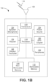
- FIG. 1B is a system diagram illustrating an example WTRU 102.
- the WTRU 102 may include a processor 118, a transceiver 120, a transmit/receive element 122, a speaker/microphone 124, a keypad 126, a display/touchpad 128, non-removable memory 130, removable memory 132, a power source 134, a global positioning system (GPS) chipset 136, and/or other peripherals 138, among others.
- GPS global positioning system
- the transmit/receive element 122 may be configured to transmit signals to, or receive signals from, a base station (e.g., the base station 114a) over the air interface 116.
- a base station e.g., the base station 114a
- the transmit/receive element 122 may be an antenna configured to transmit and/or receive RF signals.
- the transmit/receive element 122 may be an emitter/detector configured to transmit and/or receive IR, UV, or visible light signals, for example.
- the transmit/receive element 122 may be configured to transmit and/or receive both RF and light signals. It will be appreciated that the transmit/receive element 122 may be configured to transmit and/or receive any combination of wireless signals.
- the WTRU 102 may include any number of transmit/receive elements 122. More specifically, the WTRU 102 may employ MIMO technology. Thus, in one embodiment, the WTRU 102 may include two or more transmit/receive elements 122 (e.g., multiple antennas) for transmitting and receiving wireless signals over the air interface 116.
- the processor 118 of the WTRU 102 may be coupled to, and may receive user input data from, the speaker/microphone 124, the keypad 126, and/or the display/touchpad 128 (e.g., a liquid crystal display (LCD) display unit or organic light-emitting diode (OLED) display unit).
- the processor 118 may also output user data to the speaker/microphone 124, the keypad 126, and/or the display/touchpad 128.
- the processor 118 may access information from, and store data in, any type of suitable memory, such as the non-removable memory 130 and/or the removable memory 132.
- the peripherals 138 may include one or more sensors, the sensors may be one or more of a gyroscope, an accelerometer, a hall effect sensor, a magnetometer, an orientation sensor, a proximity sensor, a temperature sensor, a time sensor; a geolocation sensor; an altimeter, a light sensor, a touch sensor, a magnetometer, a barometer, a gesture sensor, a biometric sensor, and/or a humidity sensor.
- a gyroscope an accelerometer, a hall effect sensor, a magnetometer, an orientation sensor, a proximity sensor, a temperature sensor, a time sensor; a geolocation sensor; an altimeter, a light sensor, a touch sensor, a magnetometer, a barometer, a gesture sensor, a biometric sensor, and/or a humidity sensor.
- the WRTU 102 may include a half-duplex radio for which transmission and reception of some or all of the signals (e.g., associated with particular subframes for either the UL (e.g., for transmission) or the downlink (e.g., for reception)).
- a half-duplex radio for which transmission and reception of some or all of the signals (e.g., associated with particular subframes for either the UL (e.g., for transmission) or the downlink (e.g., for reception)).
- the WTRU is described in FIGS. 1A-1B as a wireless terminal, it is contemplated that in certain representative embodiments that such a terminal may use (e.g., temporarily or permanently) wired communication interfaces with the communication network.
- one or more, or all, of the functions described herein may be performed by one or more emulation devices (not shown).
- the emulation devices may be one or more devices configured to emulate one or more, or all, of the functions described herein.
- the emulation devices may be used to test other devices and/or to simulate network and/or WTRU functions.
- the emulation devices may be designed to implement one or more tests of other devices in a lab environment and/or in an operator network environment.
- the one or more emulation devices may perform the one or more, or all, functions while being fully or partially implemented and/or deployed as part of a wired and/or wireless communication network in order to test other devices within the communication network.
- the one or more emulation devices may perform the one or more, or all, functions while being temporarily implemented/deployed as part of a wired and/or wireless communication network.
- the emulation device may be directly coupled to another device for purposes of testing and/or may performing testing using over-the-air wireless communications.
- the one or more emulation devices may perform the one or more, including all, functions while not being implemented/deployed as part of a wired and/or wireless communication network.
- the emulation devices may be utilized in a testing scenario in a testing laboratory and/or a non-deployed (e.g., testing) wired and/or wireless communication network in order to implement testing of one or more components.
- the one or more emulation devices may be test equipment. Direct RF coupling and/or wireless communications via RF circuitry (e.g., which may include one or more antennas) may be used by the emulation devices to transmit and/or receive data.
- RF circuitry e.g., which may include one or more antennas
- FIG. 2 is a functional block diagram of an example of a block-based hybrid video encoding system.
- the input video signal 103 is processed block by block.
- the blocks may be referred to as coding units (CUs).
- CUs coding units
- a CU can be up to 128x128 pixels.
- a coding tree unit CTU may be split into CUs to adapt to varying local characteristics based on quad/binary/ternary-tree.
- spatial prediction (161) and/or temporal prediction (163) may be performed.
- Spatial prediction (or “intra prediction”) uses pixels from the samples of already coded neighboring blocks (which are called reference samples) in the same video picture/slice to predict the current video block. Spatial prediction reduces spatial redundancy inherent in the video signal.
- Temporal prediction (also referred to as “inter prediction” or “motion compensated prediction”) uses reconstructed pixels from the already-coded video pictures to predict the current video block. Temporal prediction reduces temporal redundancy inherent in the video signal.
- Temporal prediction signal for a given CU is usually signaled by one or more motion vectors (MVs) which indicate the amount and the direction of motion between the current CU and its temporal reference. Also, if multiple reference pictures are supported, a reference picture index is additionally sent, which is used to identify from which reference picture in the reference picture store (165) the temporal prediction signal comes.
- MVs motion vectors
- FIG. 4 is a functional block diagram of a block-based video decoder.
- the video bit-stream 202 is unpacked and entropy decoded at entropy decoding unit 208.
- the coding mode and prediction information are sent to either the spatial prediction unit 260 (if intra coded) or the temporal prediction unit 262 (if inter coded) to form the prediction block.
- the residual transform coefficients are sent to inverse quantization unit 210 and inverse transform unit 212 to reconstruct the residual block.
- the prediction block and the residual block are then added together at 226.
- the reconstructed block may further go through in-loop filtering before it is stored in reference picture store 264.
- the reconstructed video in reference picture store is then sent out to drive a display device, as well as used to predict future video blocks.
- BMS-1.0 adheres to the same encoding/decoding workflow of the VTM-1.0 as shown in FIG. 2 and FIG. 4 .
- several coding modules especially the ones associated with temporal prediction, are further extended and enhanced.
- some inter tools that are included in BMS-1.0 or the previous JEM are briefly described.
- FIG. 5 shows an example for spatial MV prediction.
- the square CurrCU is the current CU, which has the best matching block CurrRefCU in the reference picture (CurrRefPic).
- CurrCU's MV i.e., MV2
- the current CU's spatial neighborhood could be the upper, left, upper-left, bottom-left, upper-right neighboring CU of the current CU.
- the neighboring CU is shown as the upper neighbor, NeighbCU.
- NeighbCU's reference picture (NeighbRefPic) and MV (MV1) are both known, because NeighbCU has been coded before CurrCU.
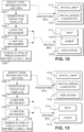
- non-refined motion vectors for a first block are identified at 1100.
- the non-refined motion vectors may have been signaled for the first block using any of a variety of available MV signaling techniques.
- the non-refined motion vectors are used at 1102 to generate a bi-prediction template.
- motion refinement is performed for the L0 motion vector
- motion refinement is performed for the L1 motion vector.
- the final bi-prediction of the first block is generated using the refined L0 and L1 motion vectors.
- the non-refined motion vectors are used to predict the motion of subsequently-coded blocks (e.g. a second block).
- the refined motion vectors are also used to calculate the boundary strength value of the deblocking filter (1218).
- non-refined motion vectors for a first block are identified at 1300.
- the non-refined motion vectors may have been signaled for the first block using any of a variety of available MV signaling techniques.
- the non-refined motion vectors are used at 1302 to generate a bi-prediction template.
- motion refinement is performed for the L0 motion vector
- motion refinement is performed for the L1 motion vector.
- the final bi-prediction of the first block is generated using the refined L0 and L1 motion vectors.
- the non-refined motion vectors are used to predict the motion of subsequently-coded blocks (e.g.
- the non-refined motion vectors are used for spatial AMVP (1310) and as spatial merge candidates (1312).
- the non-refined motion vectors are also used to calculate the boundary strength value of the deblocking filter (1314).
- the refined motion vectors are used to predict the motion of subsequently-coded blocks (e.g. a third block) in other pictures, for example using TMVP (1316) or ATMVP (1318).
- FIGs. 11-13 may reduce or remove the encoding/decoding latency caused by the DMVR, given that the dependency of the decoding of one block on the reconstruction of the refined MVs of its spatial neighboring DMVR blocks is not present in those embodiments.
- FIG. 14 illustrates an example of a parallel decoding process when one of the methods of FIGs. 11-13 is applied. As shown in FIG. 14 , because the decoding of multiple DMVR blocks can be performed in parallel, there is no decoding latency between neighboring blocks. Correspondingly, the total decoding time may be equal to the decoding of one block, which may be represented as T MCP + T DMVR +T de-quant + T inv-trans .
- a picture is divided into a plurality of non-overlapped segments, and the non-refined MVs of each DMVR block in a segment are used as the predictors to predict the MVs of its neighboring blocks in the same segment.
- the non-refined MVs of each DMVR block in a segment are used as the predictors to predict the MVs of its neighboring blocks in the same segment.
- the refined MVs of the block are used as the predictor to predict the MVs of the blocks from the neighboring segment for better efficiency of spatial motion prediction.
- the blocks on the left boundaries of segment #2 may use the refined MVs of the neighboring DMVR blocks in segment #1 as spatial MV predictors, their decoding processes cannot be started until the DMVR of those neighboring blocks in segment #1 are fully done.
- the same MVs of one DMVR block are used for the spatial motion predictions and the deblocking filter to avoid increasing the on-chip memory for storing MVs.
- non-refined motion vectors for a first block are identified at 1502.
- the non-refined motion vectors may have been signaled for the first block using any of a variety of available MV signaling techniques.
- the non-refined motion vectors are used at 1504 to generate a bi-prediction template.
- motion refinement is performed for the L0 motion vector
- motion refinement is performed for the L1 motion vector.
- the final bi-prediction of the first block is generated using the refined L0 and L1 motion vectors.
- the refined motion vectors are used to calculate the boundary strength value of the deblocking filter (1518). Regardless of the outcome of the determination at 1512, the refined motion vectors are used to predict the motion of subsequently-coded blocks (e.g. a third block) in other pictures, for example using TMVP (1520) or ATMVP (1522).
- this method it is also proposed to prohibit the current block from using the MVs (either non-refined MV or refined MV) of a neighboring block that is from another segment as the predictors for the spatial motion predictions (e.g., spatial AMVP and spatial merge). Specifically, by such method, if a neighboring block is from a different segment to the current block, it will be treated as unavailable for spatial motion vector prediction.
- MVs either non-refined MV or refined MV
- the blank blocks represent the CUs that are allowed to use the neighboring MVs (the neighboring MV could be refined MVs if the neighboring block is one DMVR block or non-refined MV if otherwise) for spatial motion predictions;
- the patterned blocks represent the CUs that are prevented from using the MVs of its neighboring blocks from a different segment for spatial motion prediction
- An embodiment according to FIG. 17 allows parallelized decoding of inter blocks across segments, but not within one segment.
- the encoder/decoder determines whether the constraint is applied or not based on examining the POC of all the reference pictures in L0 and L1 without additional signaling.
- the number of CTUs in each segment may be signaled in the Sequence Parameter Set (SPS) and/or the Picture Parameter Set (PPS), or may be signaled in the slice header.
- SPS Sequence Parameter Set
- PPS Picture Parameter Set
- Other variations of syntax elements may be used, for example, the number of CTU rows may be used, or the number of segment in each picture/slice may be used, among other alternatives.
- Additional embodiments described herein operate to replace the block-matching motion search for calculating the DMVR motion refinement.
- example embodiments directly calculate a motion refinement based on the spatial and temporal sample derivatives. Such embodiments reduce the computational complexity and may increase the motion refinement precision because the value of the derived refined motion is not limited to the search window.
- BIO was used in the JEM to provide sample-wise motion refinement on top of the block-based motion compensated prediction when a block is bi-predicted. Based on the current design, BIO only enhances the motion compensated prediction samples as the outcome of the refinement without updating the MVs that are stored in the MV buffers and used for the spatial and temporal motion prediction and deblocking filter. This means that, as opposed to the current DMVR, BIO does not introduce any encoding/decoding latency between neighboring blocks. However, in the current BIO design, the motion refinement is derived on a small unit (e.g., 4x4). This may incur non-negligible computational complexity, especially at the decoder-side. This is undesirable for hardware codec implementations.
- a small unit e.g. 4x4
- BIO block-based BIO
- the BIO core design e.g., the calculation of the gradients and the refined motion vectors
- the amount of motion refinement is derived based on CU-level, with a single value being aggregated for all the samples inside a CU and used to calculate a single motion refinement; and all samples inside the current CU will share the same motion refinement.
- v x ⁇ v y ⁇ argmin v x v y ⁇ i j ⁇ ⁇ ⁇ 2 i j
- ⁇ is set of the coordinates of the samples within the current CU
- ⁇ (x, y) is an optical flow error metric as set forth in Equation 3, above.
- BIO a motivation of BIO is to improve the precision of prediction samples based on the local gradient information at each sample location inside the current block. For large video blocks that contain many samples, it is possible that the local gradient at different sample locations may show quite varying characteristics. In such case, the above block-based BIO derivation may not provide a reliable motion refinement for the current block, therefore leading to coding performance loss. Based on such consideration, in some embodiments, it is proposed to only enable the CU-based BIO motion derivation for the DMVR blocks when its block size is small (e.g., no larger than one given threshold).
- the CU-based BIO motion derivation is disabled; instead, the existing block-matching based motion refinement (with the proposed DMVR latency removal/reduction methods described above being applied in some embodiments) will be used to derive the local motion refinement for the current block.
- v x 0 / 1 and v y 0 / 1 are the horizontal and vertical motion refinement associated with the prediction list L0 and L1.
- v x 0 / 1 and v y 0 / 1 are the horizontal and vertical motion refinement associated with the prediction list L0 and L1.
- such assumption may be not true for the blocks that are coded by the DMVR. For example, in the existing DMVR (as shown in FIG.
- two separate block-matching based motion searches are performed for L0 and L1 such that the MVs that minimize the template costs of the L0 and L1 prediction signals may be different. Due to such symmetric motion constraint, the motion refinements derived by the BIO may not always be sufficiently accurate to enhance the prediction quality (sometimes may even degrade the prediction quality) for the DMVR.
- an improved motion derivation method is used to calculate the motion refinement for the DMVR.
- Eq. (7) can be discretized by changing the optical flow function from continuous domain to discrete domain.
- one or more error metrics may be defined based on an extent to which the expression on the left in Eq. (9) is not equal to zero. Motion refinements may be employed to substantially minimize the error metric.
- a bi-prediction template is generated by averaging the two prediction blocks using the initial L0 and L1 MVs of the merge candidate.
- the optical flow model instead of performing block-matching motion search in a local region, the optical flow model in Eq.
- P 0 and P 1 are the prediction signals that are generated using the original MVs for the reference list L0 and L1, respectively, P tmp is the bi-prediction template signal
- G x 0 / G y 0 and G x 1 / G y 1 are the horizontal/vertical gradients of prediction signals P° and P 1 , which can be calculated based on different gradient filters, e.g., the Sobel filter or the 2D separable gradient filters used by BIO, as described in J.
- Equation (9) represents a set of equations: one equation for each sample in the prediction signal P 0 or P 1 for which one individual G x k , G y k and P tmp - P k can be calculated.
- such a method may select the motion refinements (i.e., ( ⁇ x, ⁇ y ) * k ) in a recursive manner.
- Such embodiments may operate by generating the initial bi-prediction template signal using the original L0 and L1 MVs of the current block and calculating the corresponding delta motion ( ⁇ x , ⁇ y ) * k based on Eq. (11); the refined MVs are then used as the motion to generate the new L0 and L1 prediction samples as well as the bi-prediction template samples, which are then used to update the values of the local refinement ( ⁇ x , ⁇ y ) * k .
- This process may be repeated until the MVs are not updated or the maximum number of iterations is reached.
- One example of such a process is summarized by the following procedures, as illustrated in FIG. 18 .
- the initial L0 and L1 prediction signals P l 0 and P l 1 and the initial bi-prediction template signal P l tmp are generated using the original MVs MV l 0 and MV l 1 of the block.
- the final bi-prediction may be generated at 1814 using the refined motion vectors. Otherwise, the counter l is incremented at 1816, and the process is iterated, with the L0 and L1 prediction signals P l + 1 0 and P l + 1 1 and the bi-prediction template signal P l + 1 tmp being updated (at 1806, 1808) using the MVs MV l + 1 0 and MV l + 1 1 .
- FIG. 18 illustrates an example of a DMVR process using an example optical-flow-based motion derivation method for calculating the motion refinements of a DMVR block.
- the optical MVs of one DMVR block is identified by iteratively modifying the original MVs based on the optical flow model.
- it also introduces a high amount of complexity increase.
- it is proposed to only apply one iteration for deriving the motion refinement using the proposed motion derivation method, e.g., to only apply the process illustrated at 1804 through 1808 to derive the modified MVs of a DMVR block.
- the optical-flow-based motion derivation model may be more efficient for small CUs than large CUs, due to the high consistency among the samples' characteristics inside a small block.
- it is proposed to enable the proposed optical-flow-based motion derivation for the DMVR blocks when its block size is small (e.g., no larger than a given threshold). Otherwise, the existing block-matching based motion refinement will be used to derive the local motion refinement for the current block (e.g. along with the proposed DMVR latency removal/reduction methods described herein).
- modules that carry out (i.e., perform, execute, and the like) various functions that are described herein in connection with the respective modules.
- a module includes hardware (e.g., one or more processors, one or more microprocessors, one or more microcontrollers, one or more microchips, one or more application-specific integrated circuits (ASICs), one or more field programmable gate arrays (FPGAs), one or more memory devices) deemed suitable by those of skill in the relevant art for a given implementation.
- ASICs application-specific integrated circuits
- FPGAs field programmable gate arrays
- Each described module may also include instructions executable for carrying out the one or more functions described as being carried out by the respective module, and it is noted that those instructions could take the form of or include hardware (i.e., hardwired) instructions, firmware instructions, software instructions, and/or the like, and may be stored in any suitable non-transitory computer-readable medium or media, such as commonly referred to as RAM, ROM, etc.
- ROM read only memory
- RAM random access memory
- register cache memory
- semiconductor memory devices magnetic media such as internal hard disks and removable disks, magneto-optical media, and optical media such as CD-ROM disks, and digital versatile disks (DVDs).
- a processor in association with software may be used to implement a radio frequency transceiver for use in a WTRU, UE, terminal, base station, RNC, or any host computer.
- a block-based video coding method comprising:
- refining the first non-refined motion vector and the second non-refined motion vector comprises selecting the first refined motion vector and the second refined motion vector to substantially minimize an error metric.
- A7 The method of any of embodiments A1-A6, further comprising predicting motion information of a third block using at least one of the first refined motion vector and the second refined motion vector, wherein the third block and the first block are collocated blocks in different pictures.
- A8 The method of embodiment A7, wherein predicting motion information of the third block is performed using advanced temporal motion vector prediction (ATMVP).
- ATMVP advanced temporal motion vector prediction
- A9 The method of any of embodiments A1-A8, wherein predicting motion information of the second block comprises using spatial advanced motion vector prediction (AMVP).
- AMVP spatial advanced motion vector prediction
- predicting motion information of the second block comprises using at least one of the first non-refined motion vector and the second non-refined motion vector as a spatial merge candidate.
- predicting the motion information of the second block comprises receiving at least one index identifying the first non-refined motion vector or the second non-refined motion vector.
- A13 The method of any of embodiments A1-A11, further comprising generating an inter prediction of the second block using at least one of the first non-refined motion vector and the second non-refined motion vector.
- A14 The method of any of embodiments A 1-A 13, further comprising determining a deblocking filter strength for the first block based at least in part on the first non-refined motion vector and the second non-refined motion vector.
- a video coding system comprising a processor and a non-transitory computer-readable medium storing instructions operative to perform functions comprising video coding method comprising:
Landscapes
- Engineering & Computer Science (AREA)
- Multimedia (AREA)
- Signal Processing (AREA)
- Computing Systems (AREA)
- Theoretical Computer Science (AREA)
- Compression Or Coding Systems Of Tv Signals (AREA)
- Compression, Expansion, Code Conversion, And Decoders (AREA)
Applications Claiming Priority (3)
| Application Number | Priority Date | Filing Date | Title |
|---|---|---|---|
| US201862690507P | 2018-06-27 | 2018-06-27 | |
| PCT/US2019/038300 WO2020005719A1 (fr) | 2018-06-27 | 2019-06-20 | Procédés et appareil de réduction de latence de codage d'un affinement de mouvement côté décodeur |
| EP19736899.6A EP3815374B1 (fr) | 2018-06-27 | 2019-06-20 | Procédés et appareil de réduction de latence de codage d'un affinement de mouvement côté décodeur |
Related Parent Applications (2)
| Application Number | Title | Priority Date | Filing Date |
|---|---|---|---|
| EP19736899.6A Division-Into EP3815374B1 (fr) | 2018-06-27 | 2019-06-20 | Procédés et appareil de réduction de latence de codage d'un affinement de mouvement côté décodeur |
| EP19736899.6A Division EP3815374B1 (fr) | 2018-06-27 | 2019-06-20 | Procédés et appareil de réduction de latence de codage d'un affinement de mouvement côté décodeur |
Publications (2)
| Publication Number | Publication Date |
|---|---|
| EP4465630A2 true EP4465630A2 (fr) | 2024-11-20 |
| EP4465630A3 EP4465630A3 (fr) | 2025-02-12 |
Family
ID=67185748
Family Applications (2)
| Application Number | Title | Priority Date | Filing Date |
|---|---|---|---|
| EP24204881.7A Pending EP4465630A3 (fr) | 2018-06-27 | 2019-06-20 | Procédés et appareil pour réduire la latence de codage d'affinement de mouvement côté décodeur |
| EP19736899.6A Active EP3815374B1 (fr) | 2018-06-27 | 2019-06-20 | Procédés et appareil de réduction de latence de codage d'un affinement de mouvement côté décodeur |
Family Applications After (1)
| Application Number | Title | Priority Date | Filing Date |
|---|---|---|---|
| EP19736899.6A Active EP3815374B1 (fr) | 2018-06-27 | 2019-06-20 | Procédés et appareil de réduction de latence de codage d'un affinement de mouvement côté décodeur |
Country Status (9)
| Country | Link |
|---|---|
| US (4) | US11546628B2 (fr) |
| EP (2) | EP4465630A3 (fr) |
| JP (3) | JP7414742B2 (fr) |
| KR (2) | KR102889229B1 (fr) |
| CN (2) | CN112369032B (fr) |
| AU (2) | AU2019295574B2 (fr) |
| MX (2) | MX2021000129A (fr) |
| TW (2) | TWI805788B (fr) |
| WO (1) | WO2020005719A1 (fr) |
Families Citing this family (30)
| Publication number | Priority date | Publication date | Assignee | Title |
|---|---|---|---|---|
| WO2020005719A1 (fr) * | 2018-06-27 | 2020-01-02 | Vid Scale, Inc. | Procédés et appareil de réduction de latence de codage d'un affinement de mouvement côté décodeur |
| CN111083484B (zh) | 2018-10-22 | 2024-06-28 | 北京字节跳动网络技术有限公司 | 基于子块的预测 |
| CN111083489B (zh) | 2018-10-22 | 2024-05-14 | 北京字节跳动网络技术有限公司 | 多次迭代运动矢量细化 |
| CN111436227B (zh) | 2018-11-12 | 2024-03-29 | 北京字节跳动网络技术有限公司 | 在视频处理中使用组合帧间-帧内预测 |
| WO2020103852A1 (fr) | 2018-11-20 | 2020-05-28 | Beijing Bytedance Network Technology Co., Ltd. | Calcul de différence basé sur une position partielle |
| WO2020103877A1 (fr) | 2018-11-20 | 2020-05-28 | Beijing Bytedance Network Technology Co., Ltd. | Codage et décodage de modes de codage vidéo |
| CN112514384B (zh) | 2019-01-28 | 2024-12-24 | 苹果公司 | 视频信号编码/解码方法及其装置 |
| JP7072088B2 (ja) | 2019-02-08 | 2022-05-19 | パナソニック インテレクチュアル プロパティ コーポレーション オブ アメリカ | 符号化装置及び復号装置 |
| KR102635518B1 (ko) | 2019-03-06 | 2024-02-07 | 베이징 바이트댄스 네트워크 테크놀로지 컴퍼니, 리미티드 | 변환된 단예측 후보의 사용 |
| JP7307192B2 (ja) | 2019-04-02 | 2023-07-11 | 北京字節跳動網絡技術有限公司 | デコーダ側の動きベクトルの導出 |
| WO2020233660A1 (fr) | 2019-05-21 | 2020-11-26 | Beijing Bytedance Network Technology Co., Ltd. | Dérivation de candidat de mouvement basée sur la syntaxe dans un mode de fusion de sous-bloc |
| WO2021001220A1 (fr) * | 2019-07-01 | 2021-01-07 | Interdigital Vc Holdings France, Sas | Affinement de flux optique bidirectionnel de compensation de mouvement affine |
| EP4011082B1 (fr) | 2019-08-08 | 2025-10-22 | Sharp Kabushiki Kaisha | Dispositif et procédé de codage de données vidéo |
| EP3997869A4 (fr) | 2019-08-10 | 2022-10-26 | Beijing Bytedance Network Technology Co., Ltd. | Signalisation dépendante de sous-images dans des flux de données vidéo |
| CN114402591B (zh) | 2019-09-13 | 2024-08-02 | 北京字节跳动网络技术有限公司 | 并置运动矢量的推导 |
| WO2021052491A1 (fr) | 2019-09-19 | 2021-03-25 | Beijing Bytedance Network Technology Co., Ltd. | Dérivation de positions d'échantillon de référence dans un codage vidéo |
| WO2021052490A1 (fr) | 2019-09-19 | 2021-03-25 | Beijing Bytedance Network Technology Co., Ltd. | Fenêtre de mise à l'échelle dans un codage vidéo |
| CN118890491A (zh) | 2019-10-05 | 2024-11-01 | 北京字节跳动网络技术有限公司 | 基于级别的视频编解码工具的信令通知 |
| CN114556918B (zh) * | 2019-10-12 | 2025-08-12 | 北京字节跳动网络技术有限公司 | 细化视频编解码工具的使用和信令 |
| JP7414980B2 (ja) | 2019-10-13 | 2024-01-16 | 北京字節跳動網絡技術有限公司 | 参照ピクチャリサンプリングと映像コーディングツールとの間の相互作用 |
| CN114631321B (zh) | 2019-10-18 | 2024-04-12 | 北京字节跳动网络技术有限公司 | 子图片与环路滤波之间的相互影响 |
| CN115280774B (zh) | 2019-12-02 | 2025-08-19 | 抖音视界有限公司 | 视觉媒体处理的方法、装置及非暂时性计算机可读存储介质 |
| JP2023011955A (ja) * | 2019-12-03 | 2023-01-25 | シャープ株式会社 | 動画像符号化装置、動画像復号装置 |
| MX2022007503A (es) | 2019-12-27 | 2022-07-04 | Beijing Bytedance Network Tech Co Ltd | Se?alizacion de tipos de corte en encabezados de imagenes de video. |
| KR20220157950A (ko) | 2020-03-23 | 2022-11-29 | 베이징 바이트댄스 네트워크 테크놀로지 컴퍼니, 리미티드 | 어파인 머지 및 어파인 모션 벡터 예측 모드에 대한 예측 리파인먼트 |
| EP4315860A4 (fr) * | 2021-03-29 | 2025-02-19 | Beijing Dajia Internet Information Technology Co., Ltd. | Compensation de mouvement à blocs recouvrants pour inter-prédiction |
| US11917176B2 (en) | 2021-09-28 | 2024-02-27 | Avago Technologies International Sales Pte. Limited | Low-latency and high-throughput motion vector refinement with template matching |
| US12549735B2 (en) * | 2022-06-20 | 2026-02-10 | Tencent America LLC | Bilateral matching for compound reference mode |
| US12464156B2 (en) * | 2022-09-21 | 2025-11-04 | Tencent America LLC | Method and apparatus for motion vector prediction based on subblock motion vector |
| WO2024210793A1 (fr) * | 2023-04-06 | 2024-10-10 | Telefonaktiebolaget Lm Ericsson (Publ) | Codeur pour coder des images d'une vidéo |
Family Cites Families (14)
| Publication number | Priority date | Publication date | Assignee | Title |
|---|---|---|---|---|
| US10536701B2 (en) * | 2011-07-01 | 2020-01-14 | Qualcomm Incorporated | Video coding using adaptive motion vector resolution |
| US9491460B2 (en) | 2013-03-29 | 2016-11-08 | Qualcomm Incorporated | Bandwidth reduction for video coding prediction |
| US9667996B2 (en) | 2013-09-26 | 2017-05-30 | Qualcomm Incorporated | Sub-prediction unit (PU) based temporal motion vector prediction in HEVC and sub-PU design in 3D-HEVC |
| US11477477B2 (en) * | 2015-01-26 | 2022-10-18 | Qualcomm Incorporated | Sub-prediction unit based advanced temporal motion vector prediction |
| US10200711B2 (en) * | 2015-03-27 | 2019-02-05 | Qualcomm Incorporated | Motion vector derivation in video coding |
| CN116708776A (zh) * | 2016-07-18 | 2023-09-05 | 韩国电子通信研究院 | 图像编码/解码方法和装置以及存储比特流的记录介质 |
| US11638027B2 (en) * | 2016-08-08 | 2023-04-25 | Hfi Innovation, Inc. | Pattern-based motion vector derivation for video coding |
| US12063387B2 (en) * | 2017-01-05 | 2024-08-13 | Hfi Innovation Inc. | Decoder-side motion vector restoration for video coding |
| KR102553762B1 (ko) * | 2017-03-20 | 2023-07-11 | 지이 비디오 컴프레션, 엘엘씨 | 고급 비디오 데이터 스트림 추출 및 다중 해상도 비디오 송신 |
| WO2018226015A1 (fr) * | 2017-06-09 | 2018-12-13 | 한국전자통신연구원 | Procédé et dispositif de codage/de décodage vidéo, et support d'enregistrement stockant un flux binaire |
| ES2982369T3 (es) * | 2017-06-30 | 2024-10-15 | Huawei Tech Co Ltd | Resiliencia de errores y procesamiento en paralelo para derivación de vector de movimiento de lado de decodificador |
| CN116962717A (zh) * | 2018-03-14 | 2023-10-27 | Lx 半导体科技有限公司 | 图像编码/解码方法、存储介质和发送方法 |
| JP7666928B2 (ja) * | 2018-05-28 | 2025-04-22 | インターデジタル ヴイシー ホールディングス, インコーポレイテッド | 符号化/復号化におけるデータ依存関係 |
| WO2020005719A1 (fr) | 2018-06-27 | 2020-01-02 | Vid Scale, Inc. | Procédés et appareil de réduction de latence de codage d'un affinement de mouvement côté décodeur |
-
2019
- 2019-06-20 WO PCT/US2019/038300 patent/WO2020005719A1/fr not_active Ceased
- 2019-06-20 AU AU2019295574A patent/AU2019295574B2/en active Active
- 2019-06-20 US US17/256,155 patent/US11546628B2/en active Active
- 2019-06-20 CN CN201980044209.9A patent/CN112369032B/zh active Active
- 2019-06-20 MX MX2021000129A patent/MX2021000129A/es unknown
- 2019-06-20 KR KR1020207037636A patent/KR102889229B1/ko active Active
- 2019-06-20 KR KR1020257038441A patent/KR20250167130A/ko active Pending
- 2019-06-20 CN CN202411401376.3A patent/CN119110093A/zh active Pending
- 2019-06-20 JP JP2020572893A patent/JP7414742B2/ja active Active
- 2019-06-20 EP EP24204881.7A patent/EP4465630A3/fr active Pending
- 2019-06-20 EP EP19736899.6A patent/EP3815374B1/fr active Active
- 2019-06-24 TW TW108122003A patent/TWI805788B/zh active
- 2019-06-24 TW TW112118968A patent/TWI885375B/zh active
-
2021
- 2021-01-06 MX MX2024007476A patent/MX2024007476A/es unknown
-
2022
- 2022-12-05 US US18/075,169 patent/US11973974B2/en active Active
-
2023
- 2023-04-11 AU AU2023202182A patent/AU2023202182B2/en active Active
- 2023-12-28 JP JP2023222829A patent/JP7633365B2/ja active Active
-
2024
- 2024-04-01 US US18/623,846 patent/US12395674B2/en active Active
-
2025
- 2025-02-06 JP JP2025018355A patent/JP2025065340A/ja active Pending
- 2025-07-23 US US19/278,375 patent/US20250350761A1/en active Pending
Non-Patent Citations (1)
| Title |
|---|
| J. CHENE. ALSHINAG. J. SULLIVANJ. R. OHMJ. BOYCE: "Algorithm description of joint exploration test model 6", JVET-G1 001, July 2017 (2017-07-01) |
Also Published As
| Publication number | Publication date |
|---|---|
| TWI885375B (zh) | 2025-06-01 |
| CN112369032A (zh) | 2021-02-12 |
| KR20250167130A (ko) | 2025-11-28 |
| TWI805788B (zh) | 2023-06-21 |
| JP2021528921A (ja) | 2021-10-21 |
| EP3815374B1 (fr) | 2024-11-20 |
| JP7414742B2 (ja) | 2024-01-16 |
| AU2023202182B2 (en) | 2024-08-22 |
| JP2024029161A (ja) | 2024-03-05 |
| JP7633365B2 (ja) | 2025-02-19 |
| EP3815374A1 (fr) | 2021-05-05 |
| CN112369032B (zh) | 2024-10-22 |
| US12395674B2 (en) | 2025-08-19 |
| EP4465630A3 (fr) | 2025-02-12 |
| US20210274213A1 (en) | 2021-09-02 |
| MX2021000129A (es) | 2021-03-25 |
| US20230120362A1 (en) | 2023-04-20 |
| TW202015412A (zh) | 2020-04-16 |
| TW202345596A (zh) | 2023-11-16 |
| WO2020005719A1 (fr) | 2020-01-02 |
| US20250350761A1 (en) | 2025-11-13 |
| US11546628B2 (en) | 2023-01-03 |
| KR20210029160A (ko) | 2021-03-15 |
| MX2024007476A (es) | 2024-07-09 |
| AU2019295574A1 (en) | 2021-01-28 |
| US11973974B2 (en) | 2024-04-30 |
| AU2019295574B2 (en) | 2023-01-12 |
| US20240244253A1 (en) | 2024-07-18 |
| KR102889229B1 (ko) | 2025-11-20 |
| AU2023202182A1 (en) | 2023-05-04 |
| CN119110093A (zh) | 2024-12-10 |
| JP2025065340A (ja) | 2025-04-17 |
Similar Documents
| Publication | Publication Date | Title |
|---|---|---|
| US12395674B2 (en) | Methods and apparatus for reducing the coding latency of decoder-side motion refinement | |
| US12542907B2 (en) | Adaptive motion vector precision for affine motion model based video coding | |
| US11470308B2 (en) | Complexity reduction and bit-width control for bi-directional optical flow | |
| US12200222B2 (en) | Affine motion model derivation method | |
| EP3987778B1 (fr) | Affinement de précision pour compensation de mouvement à flux optique | |
| US20260129207A1 (en) | Adaptive motion vector precision for affine motion model based video coding |
Legal Events
| Date | Code | Title | Description |
|---|---|---|---|
| PUAI | Public reference made under article 153(3) epc to a published international application that has entered the european phase |
Free format text: ORIGINAL CODE: 0009012 |
|
| STAA | Information on the status of an ep patent application or granted ep patent |
Free format text: STATUS: REQUEST FOR EXAMINATION WAS MADE |
|
| 17P | Request for examination filed |
Effective date: 20241007 |
|
| AC | Divisional application: reference to earlier application |
Ref document number: 3815374 Country of ref document: EP Kind code of ref document: P |
|
| AK | Designated contracting states |
Kind code of ref document: A2 Designated state(s): AL AT BE BG CH CY CZ DE DK EE ES FI FR GB GR HR HU IE IS IT LI LT LU LV MC MK MT NL NO PL PT RO RS SE SI SK SM TR |
|
| REG | Reference to a national code |
Ref country code: DE Ref legal event code: R079 Free format text: PREVIOUS MAIN CLASS: H04N0019436000 Ipc: H04N0019520000 |
|
| PUAL | Search report despatched |
Free format text: ORIGINAL CODE: 0009013 |
|
| AK | Designated contracting states |
Kind code of ref document: A3 Designated state(s): AL AT BE BG CH CY CZ DE DK EE ES FI FR GB GR HR HU IE IS IT LI LT LU LV MC MK MT NL NO PL PT RO RS SE SI SK SM TR |
|
| RIC1 | Information provided on ipc code assigned before grant |
Ipc: H04N 19/436 20140101ALI20250108BHEP Ipc: H04N 19/513 20140101ALI20250108BHEP Ipc: H04N 19/577 20140101ALI20250108BHEP Ipc: H04N 19/56 20140101ALI20250108BHEP Ipc: H04N 19/52 20140101AFI20250108BHEP |