EP4466977A2 - Presse à balles pour récolte agricole - Google Patents
Presse à balles pour récolte agricole Download PDFInfo
- Publication number
- EP4466977A2 EP4466977A2 EP24203957.6A EP24203957A EP4466977A2 EP 4466977 A2 EP4466977 A2 EP 4466977A2 EP 24203957 A EP24203957 A EP 24203957A EP 4466977 A2 EP4466977 A2 EP 4466977A2
- Authority
- EP
- European Patent Office
- Prior art keywords
- transfer
- wrapping
- round
- bale
- section
- Prior art date
- Legal status (The legal status is an assumption and is not a legal conclusion. Google has not performed a legal analysis and makes no representation as to the accuracy of the status listed.)
- Granted
Links
Images




Classifications
-
- A—HUMAN NECESSITIES
- A01—AGRICULTURE; FORESTRY; ANIMAL HUSBANDRY; HUNTING; TRAPPING; FISHING
- A01F—PROCESSING OF HARVESTED PRODUCE; HAY OR STRAW PRESSES; DEVICES FOR STORING AGRICULTURAL OR HORTICULTURAL PRODUCE
- A01F15/00—Baling presses for straw, hay or the like
- A01F15/07—Rotobalers, i.e. machines for forming cylindrical bales by winding and pressing
- A01F15/071—Wrapping devices
-
- A—HUMAN NECESSITIES
- A01—AGRICULTURE; FORESTRY; ANIMAL HUSBANDRY; HUNTING; TRAPPING; FISHING
- A01F—PROCESSING OF HARVESTED PRODUCE; HAY OR STRAW PRESSES; DEVICES FOR STORING AGRICULTURAL OR HORTICULTURAL PRODUCE
- A01F15/00—Baling presses for straw, hay or the like
- A01F15/08—Details
- A01F15/0875—Discharge devices
- A01F15/0883—Discharge devices for round balers
-
- A—HUMAN NECESSITIES
- A01—AGRICULTURE; FORESTRY; ANIMAL HUSBANDRY; HUNTING; TRAPPING; FISHING
- A01F—PROCESSING OF HARVESTED PRODUCE; HAY OR STRAW PRESSES; DEVICES FOR STORING AGRICULTURAL OR HORTICULTURAL PRODUCE
- A01F15/00—Baling presses for straw, hay or the like
- A01F15/07—Rotobalers, i.e. machines for forming cylindrical bales by winding and pressing
- A01F15/071—Wrapping devices
- A01F2015/0735—Combined machines that include a press bale and a wrapping device in a further step, e.g. turning table, not in the same closed pressing chamber
Definitions
- the invention relates to a method for operating a round baler for agricultural crops, which forms a pressing chamber for pressing a round bale, has a wrapping device for wrapping the pressed round bale with a wrapping material and has a transfer device which is designed to form a transfer path over which the pressed round bale can be transferred in a transfer direction from the pressing chamber to the wrapping device, and comprises at least one transfer path device which, at least in a first position, forms at least a predominant first part of the transfer path.
- a round baler is from the DE 602 24 751 T2 known.
- the disclosed round baler has two ramps as a transfer device for transferring the pressed round bale from the pressing chamber to the wrapping device. It has proven to be problematic with round balers of this type that the pressed round bales cannot be reliably transferred from the pressing chamber to the wrapping device during operation on slopes. In particular, the problem arises that round bales remain in the pressing chamber or on the transfer line during a downward journey and cannot be transferred to the wrapping device without manual intervention, which requires interrupting operation. On the other hand, when traveling uphill, the problem arises that round bales accelerate on the transfer line to such an extent that they are transferred beyond the wrapping device.
- US 2003/0024407 A1 is a method for operating a round baler for transferring a pressed round bale from a pressing chamber, which can be opened by a flap element towards the transfer device, into a wrapping device, which has a wrapping table which can be moved from a wrapping position to a receiving position on the transfer path and which forms a wrapping trough for the pressed round bale.
- the wrapping table is used for braking of the pressed round bale is moved into a bale braking position and held in the bale braking position.
- the flap element then opens the pressing chamber to discharge the pressed round bale from the pressing chamber to the transfer device.
- the wrapping table is then moved into the wrapping position to wrap the received round bale.
- the wrapped round bale is caught by a first unwinding device, which is located behind and below the discharge opening of the pressing chamber of the round baler.
- the first unwinding device is followed by a second unwinding device, which is held close to the ground when a round bale is being accepted.
- the wrapping table must first be swiveled into a vertical position to accept a round bale in order to brake the round bale, and then rotated by around 90° together with the second unwinding device before the wrapping process can be started.
- a round baler with a wrapping device is also known.
- the wrapping table disclosed there can be moved between the receiving station and the wrapping station in order to pick up a fully tied bale of crop and then wrap it with silage film. Moving the wrapping table over long distances is complex, and it is also difficult to safely pick up and brake a fully tied round bale under all operating conditions, especially when working on a slope.
- the writing EP 0 893 053 B1 also discloses a round baler with wrapping device.
- the wrapping table can be moved along guide rails to pick up a round bale and transport it to the wrapping device.
- a bale brake is arranged at the rear end of the wrapping table, which is intended to brake a bale fed to the wrapping table.
- the angle of the bale brake itself can be adjusted so that it can be moved back and forth between a braking position and a discharge position for releasing the bale from the wrapping table.
- the object of the present invention is to provide a method for operating the round baler in such a way that the reliability of the transfer of the pressed round bale is increased.
- the wrapping table is first moved to a bale braking position and/or held in the bale braking position to brake the pressed round bale.
- the bale braking position is the same as the wrapping position or is defined such that the wrapping table is arranged in the bale braking position between the wrapping position and the receiving position.
- the flap element of the pressing chamber is opened to discharge the round bale from the pressing chamber to the transfer device.
- the round bale is then transferred by means of the transfer device until it hits a front part of the wrapping table, in particular the braking roller element.
- the wrapping table is then moved to the receiving position to receive the pressed round bale, in particular along it.
- the round bale is then transferred to the wrapping table by gravity or with the help of the transfer drive element.
- the wrapping table is then moved to the wrapping position to wrap the round bale.
- the wrapping table is moved into the receiving position after a certain period of time has elapsed after the flap element has been opened and/or depending on an output signal from a bale brake sensor for detecting the round bale resting on the wrapping device, in particular on the brake roller element.
- a bale brake sensor for detecting the round bale resting on the wrapping device, in particular on the brake roller element.
- the bale braking position is set depending on the size of the round bale.
- the size is determined in particular by means of a size sensor or taken from a control unit of the round baler.
- the bale braking position is set in such a way that the distance of the wrapping table from the transfer device or from the support plane in the bale braking position increases with the size of the round bale. This prevents both a lack of braking effect for large bales and jamming of small bales between the transfer device and the wrapping device.
- the sequence of the method depends on the output signal of a bale receiving sensor for identifying a round bale arranged in the wrapping trough.
- the wrapping table is only moved into the wrapping position after identification.
- the transfer drive element is moved into the drive position when the wrapping table is arranged in the receiving position and/or the round bale has not yet been identified.
- the transfer drive element is returned to the rest position after identification. This avoids unnecessary delays in the operation of the round baler.
- the movement of the wrapping table is dependent on an inclination of the round baler.
- the time period and/or the bale braking position is determined or set depending on the inclination.
- Other process parameters can also be made dependent on the inclination to improve the process. This allows the braking effect to be optimized for each position.
- the round baler itself has an inclination sensor to determine the inclination or obtains data representing the inclination from the tractor.
- the inclination refers in particular to an inclination around a horizontal inclination axis that is perpendicular to the transfer direction.
- the round baler of the generic type or according to the invention preferably has a control device that is designed to automatically carry out the method described above.
- the control device is coupled in particular to the sensors mentioned and is designed to control the actuating element and/or a wrapping device actuating element for moving the wrapping table. This allows the above-described advantages of the method to be achieved automatically and thus with only a very low susceptibility to errors.
- the round baler is usually a mobile agricultural machine that is pulled by a tractor in one direction across an agricultural area and is designed to collect hay and/or grass as a harvested crop and to form a cylindrical and wrapped round bale from it.
- the round baler can also be designed as a self-propelled agricultural machine.
- the round baler has a chassis with at least two wheels.
- the support plane is a virtual plane that touches the wheels, does not intersect the round baler and extends in the direction of travel. When the round baler is operated on a horizontal agricultural area, the support plane extends horizontally.
- the transfer device is designed in particular such that the pressed round bale can roll or slide over the transfer path from the pressing chamber to the wrapping device, at least when the support plane is arranged horizontally, without the need for a force to be applied to the round bale in the transfer direction.
- the transfer path is preferably designed in such a way that the round bale does not undergo any significant change in direction during the transfer.
- the transfer path preferably extends at least partially inclined to the support plane.
- the transfer path is designed in particular by a plurality of elements of the transfer device or their transfer surfaces facing away from the support plane, which are spaced slightly apart from one another in the transfer direction. are such that round bales of normal size can be transferred over them in one flowing movement.
- the transfer section device is arranged between the pressing chamber and the winding device and preferably has at least some of the elements and/or the transfer surfaces. In the first position, the transfer section device forms a predominant part of the transfer section in particular in that the part of the transfer section formed by the transfer section device makes up at least half of the length of the entire transfer section measured in the transfer direction.
- the first part of the transfer section is preferably continuous and preferably comprises, depending on the position of the transfer drive element, an end of the transfer section adjacent to the pressing chamber and/or the winding device.
- the preposition "between” is to be understood in particular in such a way that a virtual straight line perpendicular to the support plane intersects both the transfer section device and the transfer drive element.
- the transfer drive element In the drive position, the transfer drive element is arranged above the transfer section device and in particular above the first part of the transfer section.
- the transfer drive element is preferably movable both relative to the transfer section device and relative to a machine frame of the round baler.
- the mobility of the transfer drive element at least partially in the transfer direction enables the pressed round bale, which is also arranged above the first part during the transfer, to be pushed in the transfer direction.
- the transfer drive element enables the pressed round bale to be reliably transferred to the wrapping device even when traveling steeply downhill.
- the transfer drive element is designed in particular as a rotatable roller, the axis of rotation of which extends transversely to the transfer direction and is movable relative to the transfer section device.
- the above and following positions are defined in particular solely by the position of the rotation axis and not by a rotational position of the transfer drive element.
- the rotatability of the transfer drive element prevents any influence on any rotation of the transferred round bale and thus its braking.
- the transfer drive element In the drive position, the transfer drive element is in particular spaced so far from the transfer section device that the force transmitted to a round bale of normal size during operation is at least in phases at least substantially directed in the transfer direction.
- the transfer drive element is mounted so as to be movable from the drive position relative to the transfer section element, in particular towards the first part and/or towards the machine frame, at least into a receiving support position in which the transfer drive element forms a second part of the transfer section. Due to this mounting of the transfer drive element, it can also contribute to the transfer of the round bale without, before or after the need to drive the round bale by optimizing the transfer section.
- the transfer drive element is mounted in such a way that the second part of the transfer path is arranged between the baling chamber and the first part of the transfer path.
- the transfer drive element in the receiving support position forms the end of the transfer path adjacent to the baling chamber. Due to this arrangement of the second part, the transfer drive element can be used during the transfer of the same round bale, initially to support the round bale and then to drive it over the remaining transfer path, thus maximizing the effectiveness of the transfer drive element.
- the round baler preferably has a flap element which, in a pressing position, also forms the pressing chamber and which, in order to open the pressing chamber, is at least partially connected to the transfer device is movable towards.
- the flap element is not part of the transfer device.
- the transfer drive element extends in the receiving support position in a spatial section that is stationary relative to the pressing chamber and/or surface section of a longitudinal section into which the flap element extends in the pressing position. The transfer drive element cannot therefore be arranged in the supporting position while the flap element is (still) arranged in the pressing position.
- the spatial section is a space whose boundaries are fictitious and which is occupied by the transfer drive element in the receiving support position.
- the spatial section is in particular cylindrical.
- this definition of the receiving support position allows the transfer section to be designed in such a way that a smooth transition for the pressed round bale from the pressing chamber to the transfer section is possible and the best possible conversion of the potential energy of the round bale in the pressing chamber into kinetic energy during the transfer is possible.
- a movement of the round bale against the transfer direction against a starter roller, which also forms the pressing chamber, is prevented.
- the transfer drive element is movable beyond the receiving support position into a rest position. In the rest position, the transfer drive element is to be arranged in particular below the flap element.
- the flap element After the flap element has been opened, it can be moved particularly quickly into the receiving support position in a conventional design. During operation, the movement takes place in particular automatically depending on the position of the flap element.
- the object is also achieved by a transfer drive element which is movably mounted in the rest position and in the receiving support position and not necessarily in the drive position.
- the transfer drive element is mounted at least partially pivotably about a drive pivot axis, from which the rotation axis is in particular at a fixed distance.
- the drive pivot axis is preferably arranged at right angles to the transfer direction. This mounting keeps the risk of failure of the transfer device low.
- the drive pivot axis is preferably arranged stationary relative to the machine frame and/or the transfer section device in the first position.
- the drive pivot axis is arranged in an intermediate space between the support plane and a reference plane, in which the transfer section device is also arranged in the first position.
- the reference plane is adjacent to the transfer section device.
- the drive pivot axis is arranged between at least part of the transfer section or the transfer section device and the support plane. This arrangement of the drive pivot axis allows the transfer drive element to be moved from the receiving support position to the drive position with just a small pivot angle.
- the transfer drive element is movably mounted in a delivery support position.
- a transfer drive device which comprises the transfer drive element and is in particular pivotable as a whole about the drive pivot axis, forms a further part of the transfer path.
- the further part of the transfer path is arranged between the first part of the transfer path formed by the transfer path device and the winding device.
- the transfer drive element is pivotable from the receiving support position through the drive position into the delivery support position.
- the transfer drive element itself or a further part of the transfer drive device forms the further part of the transfer path.
- the further part of the transfer path is in particular formed as an alternative to the second part of the transfer path.
- the transfer drive element is particularly included in the transfer drive device in such a way that, in addition to its optional ability to rotate around the axis of rotation, it can only be moved together with the other parts of the transfer drive device.
- the transfer drive element With the mobility of the transfer drive element into the delivery support position and the further part of the transfer path that can be reached as a result, the transfer drive element has a further function that supports the transfer of round bales.
- the advantage of the delivery support position is in particular that a round bale that was previously arranged between the transfer drive element in the drive position and the baling chamber on the transfer path and for which the transfer drive element represented an obstacle can still be transferred to the wrapping device.
- the transfer device preferably has at least one actuating device with an actuating element for moving the drive element at least into the drive position.
- the actuating device preferably serves to move the transfer drive element into all of its positions. For this purpose, it is further preferred that a movement of the transfer drive element is not possible without a movement of the actuating device.
- a linear actuator preferably a hydraulic, pneumatic or electric linear actuator, is provided as the actuating element. The actuating device enables the transfer drive element to be moved as required in every operating situation.
- the adjusting device is particularly preferably designed to pivot the transfer drive element by at least 15°, preferably by at least 120°, particularly preferably by at least 160°. This angle is covered in particular by a movement from the rest position to the delivery support position. This design of the adjusting device allows all useful positions to be achieved even with a compact arrangement of the drive pivot axis directly below the transfer section.
- the actuating element is at least in one of the positions of the transfer drive element and in the first position of the transfer section device at least partially arranged between the transfer section device and the support plane.
- An adjustment direction in which the adjustment element is at least partially movable is in particular angled by less than 45° to the support plane.
- the preposition "between” is to be understood in particular in such a way that a virtual straight line at right angles to the support plane intersects both the transfer section device and the adjustment element. This arrangement of the adjustment element allows it to be effectively protected from the round bale, any crop components and foreign bodies and thus from failures.
- the actuating device preferably comprises a link arrangement that couples the actuating element to the transfer drive element.
- the link arrangement comprises a first link that is pivotably mounted on the actuating element and pivotably mounted on the machine frame of the round baler.
- the link arrangement also comprises a second link that is pivotably mounted on the first link and pivotably mounted on the transfer drive element. All pivot axes are preferably arranged parallel to the drive pivot axis. Particularly preferably, the axis about which the second link is pivotably mounted on the first link corresponds to the axis about which the first link is pivotably mounted on the actuating element.
- the link arrangement enables a wide-ranging pivoting movement of the transfer drive element with only a short travel path and thus installation space for the actuating element.
- the transfer section device preferably has at least one transfer section device unit.
- the transfer section device unit is mounted so as to be pivotable about a section pivot axis relative to the machine frame of the round baler from a first position, in which it is arranged when the transfer section device is arranged in its first position, into a second position.
- the transfer section device unit is arranged in the second position when the transfer section device is also arranged in a second position. In In the second position, the transfer section device unit can also form the transfer section.
- the pivoting direction of the transfer section device unit from the first position to the second position preferably corresponds to the pivoting direction of the transfer drive element from the receiving support position to the drive position.
- the section pivot axis is arranged in particular at a distance from the drive pivot axis.
- the section pivot axis intersects the transfer section device unit in particular in its end region facing the wrapping device at least in the first position.
- the transfer section device can also have a section that also forms the transfer section and is at least partially mounted in a stationary manner to the machine frame. The pivotable mounting of the transfer section device unit makes it possible in particular to increase the gradient of the transfer section and thus further support the transfer of the round bale.
- the actuating device preferably has a transmission element by means of which it is designed to move the transfer section device unit from its first to its second position. This means that the actuating device is designed both to move the transfer drive element or the transfer drive device and to move the transfer section device unit.
- the transmission element is preferably arranged on the actuating element, the first or second link or the transfer drive device.
- the transmission element is particularly preferably a rotatable roller, the axis of rotation of which coincides in particular with the pivot axis about which the first link can pivot relative to the actuating element.
- the adjusting device is designed such that the transmission element is applied to a transmission counter element of the transfer section device unit during a movement of the transfer drive element from the receiving support position to the delivery support position. Particularly preferably it contacts the transmission counter element during a movement of the transfer drive element from the receiving support position to the drive position. In particular, the transmission element contacts the transmission counter element in a contact receiving position of the transfer drive element. With the further pivoting of the transfer drive element, the transmission element remains in contact with the transmission counter element.
- the transfer section device unit preferably has a support surface which is spaced apart from the section pivot axis and which is designed such that the transfer section device unit, at least in its first position and/or when the transfer drive element is arranged in the receiving support position and/or the rest position, rests with the support surface releasably on a support element of the machine frame.
- the support surface is arranged in particular on an end of the transfer section device unit facing away from the section pivot axis and/or facing the baling chamber.
- the transfer section device unit particularly preferably has no contact with it in the receiving support position of the transfer drive element.
- the support surface is released from the support element in particular.
- the support surface prevents unnecessary loading of the actuating device by a round bale resting on the transfer section device unit, the gravity of which is instead diverted directly into the machine frame.
- the transmission element and/or the transmission counter-element are/is formed such that the movement of the transfer section device unit from its first position ends in its second position, while the Transfer drive element is moved from the receiving support position into the delivery support position, in particular into the drive position. The movement then ends in the second position when the transfer section device unit moves back towards the first position with a further movement of the transfer drive element or remains in the second position.
- This design makes it possible on the one hand to ensure that the transfer drive element can drive the round bale as far as possible up to the wrapping device, and on the other hand to ensure that the transfer section device unit is not spaced too far from the baling chamber. This is advantageous in order to prevent any crop material escaping from the baling chamber, in particular unintentionally, from getting under part of the transfer section device, in particular in the area of the adjusting device, and leading to longer downtimes.
- the transfer counter element particularly preferably has a transfer contour in longitudinal section, which has a first contour section, which in particular runs straight, and a second contour section, which is angled to the first contour section and in particular runs straight.
- the contour sections are in particular angled to one another in such a way that the transfer section device unit can be moved into the second position when the transfer element comes into contact with the first contour section and remains in the second position or is moved back when the transfer unit comes into contact with the second contour section.
- the transfer section device comprises at least two transfer section device units. These are each spaced apart from a longitudinal center plane that is perpendicular to the support plane and parallel to the transfer direction and extends between the two transfer section device units, and are arranged in particular next to one another.
- the transfer section device units are of the same type or mirror-symmetrical to the Longitudinal center plane.
- the transfer drive device comprising the transfer drive element and/or the at least one transfer section device unit preferably have at least one frame element or in particular at least one roller element rotatably mounted on the frame element.
- the transfer drive element is designed as a roller element.
- the roller element enables the round bale to slide in the transfer direction, in which the potential energy is converted into kinetic energy more expediently than rolling. Unwinding of the round bale when being transferred from the baling chamber to the wrapping device can thus generally be avoided.
- the transfer section device unit in particular has a plurality of roller elements that are mounted between two frame elements. Alternatively or in addition to the roller elements, the transfer section device unit preferably has a sliding plate extending in the transfer direction.
- the at least one frame element is preferably exclusively pivotable relative to the machine frame and extends mainly at least substantially radially to the respective pivot axis.
- a rotation axis about which the at least one roller element of the transfer track device unit is rotatably mounted relative to the frame element encompassed thereby is arranged coaxially with the track pivot axis.
- the at least one frame element, in particular two frame elements, of the transfer drive device are arranged at least partially between the two transfer section device units in a plan view, at least in the receiving support position of the transfer drive element.
- the viewing direction is arranged in particular at right angles to the support plane.
- the transfer drive device in the delivery support position is particularly well suited to forming the further part of the transfer section by the frame element or frame elements.
- the transfer drive device preferably has two further frame elements, between which the transfer section device units are arranged in the top view.
- the frame elements of the transfer drive device are in particular offset in a transverse direction and arranged in a fixed position on a cross member of the transfer drive device.
- At least one crank element is preferably arranged in a fixed position on the cross member, which is connected to the handlebar arrangement and is arranged offset in the transverse direction to the frame elements.
- the transfer device has one adjusting device per transfer section device unit.
- a section of the frame element of the transfer drive device that is spaced apart from the drive pivot axis extends longitudinally in a section direction that is less angled to the support plane in the delivery support position of the transfer drive element than a radial related to the drive pivot axis and intersecting the section.
- the radial and the section direction are preferably angled to each other by at least 10°, in particular by at least 20°.
- the frame element particularly preferably has at least two sections that are angled to each other or is S-shaped.
- the section preferably extends to the transfer drive element. This design of the section makes it suitable for forming the further part of the transfer section without the round bale having to be significantly diverted when moving from the first part of the transfer section to the further part of the transfer section.
- An end of the transfer line device unit facing away from the line pivot axis is preferably formed by a collecting element which, at least in the first position of the transfer line device and when arranged of the transfer drive element in the receiving support position is arranged between the transfer drive element and the support plane. This also applies in particular when the transfer drive element is arranged in the rest position.
- the collecting element is preferably stationary or formed as one piece with the frame element of the transfer section device unit. The collecting element ensures, in particular in the second position of the transfer section device unit, that no gap is formed between the transfer section device and the baling chamber that is too large, through which larger quantities of crop could pass.
- the collecting element extends in particular flatly between two frame elements of the transfer section device unit.
- a collecting surface facing away from the support plane extends in longitudinal section preferably at an angle to a radial related to the section pivot axis, which intersects the collecting surface, and/or to the transfer direction.
- the collecting surface in the second position of the transfer section device unit, extends in longitudinal section in the direction of the starter roller.
- the support surface is arranged between the collecting surface and the support plane at least in the first position of the transfer section device unit.
- the transfer drive device preferably has at least one tread element between the transfer section device units.
- the tread element preferably has two tread surfaces that are angled to one another in longitudinal section, with a first tread surface particularly preferably extending at least substantially parallel to the support plane at least in the rest position of the transfer drive element and a second tread surface extending at least substantially parallel to the support plane at least in the delivery support position of the transfer drive element.
- the tread surface is particularly preferably formed by a contoured or smooth sheet metal or by a grate.
- the wrapping device comprises a wrapping table which forms a wrapping trough for the pressed round bale.
- the wrapping table preferably has a wrapping table frame and at least one rotation element which rotates relative to the wrapping table frame during operation for rotating the round bale.
- the rotation element is in particular a rotating belt.
- the wrapping table is movable relative to the machine frame, in particular at least substantially translationally.
- the wrapping table is movable relative to the machine frame, preferably from a wrapping position to a receiving position on the transfer path. In the wrapping position, in which the wrapping table frame is arranged stationary relative to the machine frame, the wrapping table is arranged while the pressed round bale is wrapped with the wrapping material.
- the wrapping table is in the receiving position while the round bale is being placed onto the wrapping table by the transfer device.
- the receiving position is in particular an end position beyond which the wrapping table cannot move from the wrapping position.
- the wrapping table is preferably arranged closer to the support plane and/or closer to the transfer device than in the wrapping position.
- the wrapping table is designed to be transferable from the receiving position beyond the wrapping position into an output position for outputting the pressed and wrapped round bale from the round baler.
- the wrapping device preferably has a brake roller element which is mounted so as to be rotatable about a brake roller axis of rotation which is fixed to the wrapping table frame.
- the brake roller element is arranged between the wrapping trough and the transfer device at least in the wrapping position. In the wrapping position, the brake roller element preferably protrudes from the wrapping table in the opposite direction to the transfer direction.
- the brake roller element serves to brake the round bale carried by the transfer device and moved in the transfer direction if the wrapping table is not (yet) arranged in the receiving position.
- the brake roller element is mounted on the changing table frame in such a way that, in the receiving position of the changing table, it is arranged between at least a part of the transfer section device and the support plane. This means that it does not hinder the usual transfer of the round bale from the transfer line to the wrapping device. Alternatively, it is conceivable that the brake roller element also forms the transfer line in the receiving position.
- the round baler 2 serves to press agricultural crops into round bales 6.
- the round baler 2 is pulled by a tractor 70 ( Fig. 1 ).
- the round baler 2 has a pressing chamber 4 for pressing the round bale 6.
- the round baler 2 has a wrapping device 8 for wrapping the pressed round bale 6 with a wrapping material.
- the round baler 2 has a transfer device 10 between the pressing chamber 4 and the wrapping device 8.
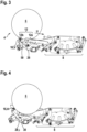
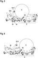
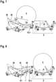
- the Fig. 2 to 12 show longitudinal sections of at least the transfer device 10 and the wrapping device 8 of the round baler 2.
- the Fig. 2 to 8 document a first procedure to be carried out with the round baler 2 for transferring the round bale 6.
- the Fig. 9 to 12 document another procedure to be carried out with the round baler 2 for transferring the round bale 6.
- the transfer device 10 is designed to form a transfer section 12, of which at least a first part 12a is formed by a transfer section device 14 of the transfer device 10 ( Fig. 3 and 7 ).
- the pressed round bale 6 can be transferred in a transfer direction U from the pressing chamber 4 to the wrapping device 8 via the transfer section 12.
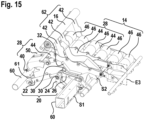
- the transfer section device 14 has twelve roller elements 46, which are arranged in two groups of six roller elements 46 each ( Fig. 14 ). Four of the roller elements 46 of each group are comprised of a transfer section device unit 28, which also comprises two frame elements 44.
- the two transfer section device units 28 are movable from a first position i (among others Fig. 2 ) about a swivel axis S2 into a second position ii (among others Fig. 5 ) pivoting.
- the transfer device 10 has a transfer drive device 62, which comprises a transfer drive element 16 and four frame elements 42.
- the transfer drive device 62 is mounted so as to be pivotable about a drive pivot axis S1.
- the drive pivot axis S1 is arranged between a support plane E1 ( Fig. 1 ) and a reference plane E2 parallel to the support plane E1 and adjacent to the transfer line device 14 ( Fig. 2 ), wherein the transfer section device 14 is arranged between the support plane E1 and the reference plane E2.
- Both pivot axes S1, S2 are arranged stationary relative to a machine frame 60.
- Fig. 2 shows a pressed round bale 6 in the pressing chamber 4.
- the pressing chamber 4 is formed during pressing, among other things, by a flap element 18 in a pressing position shown in dashed lines. It is also formed by a starter roller 72. After the round bale 6 has been completed, the flap element 18 is pivoted into the open position shown in order to discharge the round bale 6 from the pressing chamber 4.
- the transfer drive element 16 While the flap element 18 is arranged in the pressing position, the transfer drive element 16 is in the Fig. 2 shown rest position I. During opening immediately after the opening of the flap element 18, the transfer drive element is pivoted upwards by 10° to 15° into a receiving support position II ( Fig. 3 ) in which it is located between the starter roller 72 and the transfer section device 14. In the receiving support position II, the transfer drive element 16 forms a second part 12b of the transfer section 12.
- the transfer drive element 16 is further moved into a contact receiving position III ( Fig. 4 , explanations below). In the process shown, it drives the round bale 6 in the transfer direction U.
- the transfer drive element reaches the contact position III after pivoting from the rest position I by approximately 18°.
- the transfer drive element 16 is further moved into a first drive position IV ( Fig. 5 ) and a second drive position IV ( Fig. 6 ; pivoted approximately 95° from the rest position I), in which the transfer section device 14 is arranged between the transfer drive element 16 and the support plane E1. The transfer of the round bale 6 is then completed.
- the Fig. 7 and 8 concern the unintentional case that a following round bale 6 enters the area between the baling chamber 4 and the transfer drive element 16 in the second drive position IV.
- the transfer drive element 16 is movable further from the second drive position IV and from the rest position I by almost 180° into the delivery support position V shown, in which the frame elements 42 of the transfer drive device 62 form a further part 12c of the transfer section 12 between the first part 12a of the transfer section 12 and the winding device 8.
- a section 48 of the frame elements 42 is extended elongatedly in a section direction T, which in the delivery support position V is less strongly angled to the support plane E1 than a radial R1 ( Fig. 8 ).
- the transfer device 10 comprises two actuating devices 20, each of which is arranged under one of the transfer section device units 28.
- the actuating devices 20 each comprise an actuating element 22 designed as a hydraulic cylinder and a link arrangement between the actuating element 22 and the transfer drive device 62.
- the link arrangement comprises a first link 24, which is pivotably mounted on the actuating element 22 and pivotably mounted on the machine frame 60, and a second link 26, which is pivotably mounted on the first link 24 and pivotably mounted on the transfer drive device 62 ( Fig. 13 ).
- the actuating devices 20 are designed both for moving the transfer drive device 62 and for moving the transfer section device units 28.
- the actuating devices 20 have transmission elements 30 which interact with transmission counter-elements 32 included therein to move the transfer section device units 28.
- the transmission counter-elements 32 each have a transmission contour 34 which is composed of a first contour section 36 and a second contour section 38 which is angled to the first contour section 36.
- the adjusting devices 20 are designed such that the transmission elements 30 in the contact position III of the transfer drive element 16 to the transmission counter-elements 32. With an upward pivoting of the transfer drive element 16 from the contact receiving position III, the transfer section device units 28 are moved from the first position i (among others Fig. 2 ) raised to the second position ii (among other things Fig. 5 ).
- the transfer counter element 32 is designed in such a way that the movement of the transfer section device units 28 ends in the second position ii, while the transfer drive element 16 is pivoted into the second drive position IV. This avoids a gap that is too large between the starter roller 72 and the transfer section device 14.
- the collecting element 50 ( Fig. 15 ).
- the transfer section device units 28 are arranged mirror-symmetrically to a longitudinal center plane E3, which is arranged in the transfer direction U and at right angles to the support plane E1.
- a longitudinal center plane E3 which is arranged in the transfer direction U and at right angles to the support plane E1.
- Tread elements 74 are arranged between these two frame elements 42.
- the wrapping device 8 has a wrapping table 51 which forms a wrapping trough 50 for the pressed round bale 6 ( Fig. 9 ). Furthermore, the changing table 51 comprises a changing table frame 54 and four rotating elements 56 ( Fig. 14 ).
- the winding device 8 also has a brake roller element 58 which is rotatably mounted about a brake roller element rotation axis S3 which is fixed to the winding table frame 54 ( Fig. 14 ).
- the brake roller element 58 is at least in the Fig. 9 shown wrapping position W3 of the wrapping table 51, which corresponds to the bale braking position W1 is arranged between the winding trough 52 and the transfer device 10.
- the brake roller element 58 is mounted on the winding table frame 54 so as to be rotatable about a brake roller rotation axis S3, that the brake roller element 58 is in the Fig. 11 shown receiving position W2 of the wrapping table 51 is arranged between the transfer section device 14 and the attachment level E1.
- the wrapping device 8 comprises a wrapping device actuating element 90 as well as a first wrapping table guide 76 and a second wrapping table guide 78.
- a blocking device 82 is arranged on the wrapping table frame 54, which is coupled to the second wrapping table guide 78 by means of a blocking device guide 80.
- the blocking device 82 is coupled in such a way that it is arranged in a lowered position relative to the wrapping table frame 54 when the wrapping table 51 is arranged in the wrapping position W3, and is arranged in an upright position when the wrapping table 51 is arranged in the receiving position W2.
- a rotatably mounted blocking roller element 84 is arranged on the top of the blocking device 82.
- a locking roller element 86 is rotatably mounted on a locking lever 88, which is spring-loaded and pivots downwards in a yielding manner during the transfer of the round bale 6 and is intended to prevent a movement of the round bale 6 against the transfer direction U upon subsequent pivoting back.
- the wrapping table 51 is in the bale braking position W1, which is spaced apart from the transfer device 10, when the flap element 18 is opened.
- the wrapping table 51 is moved into the receiving position W2 and the round bale 6 is placed on the wrapping table 51 due to gravity.
- the blocking device 82 also prevents The round bale 6 rolls out of the wrapping table 51 during the upward travel.
- the wrapping table 51 is then moved to the wrapping position W3 to wrap the round bale 6.
Landscapes
- Life Sciences & Earth Sciences (AREA)
- Environmental Sciences (AREA)
- Storage Of Harvested Produce (AREA)
Applications Claiming Priority (2)
| Application Number | Priority Date | Filing Date | Title |
|---|---|---|---|
| DE102022115782.2A DE102022115782A1 (de) | 2022-06-24 | 2022-06-24 | Ballenpresse für landwirtschaftliches Erntegut |
| EP23181067.2A EP4295665A3 (fr) | 2022-06-24 | 2023-06-22 | Presse à balles pour récolte agricole |
Related Parent Applications (1)
| Application Number | Title | Priority Date | Filing Date |
|---|---|---|---|
| EP23181067.2A Division EP4295665A3 (fr) | 2022-06-24 | 2023-06-22 | Presse à balles pour récolte agricole |
Publications (3)
| Publication Number | Publication Date |
|---|---|
| EP4466977A2 true EP4466977A2 (fr) | 2024-11-27 |
| EP4466977A3 EP4466977A3 (fr) | 2025-05-14 |
| EP4466977B1 EP4466977B1 (fr) | 2026-03-25 |
Family
ID=86942433
Family Applications (2)
| Application Number | Title | Priority Date | Filing Date |
|---|---|---|---|
| EP23181067.2A Pending EP4295665A3 (fr) | 2022-06-24 | 2023-06-22 | Presse à balles pour récolte agricole |
| EP24203957.6A Active EP4466977B1 (fr) | 2022-06-24 | 2023-06-22 | Presse à balles pour récolte agricole |
Family Applications Before (1)
| Application Number | Title | Priority Date | Filing Date |
|---|---|---|---|
| EP23181067.2A Pending EP4295665A3 (fr) | 2022-06-24 | 2023-06-22 | Presse à balles pour récolte agricole |
Country Status (3)
| Country | Link |
|---|---|
| US (1) | US20240074357A1 (fr) |
| EP (2) | EP4295665A3 (fr) |
| DE (1) | DE102022115782A1 (fr) |
Families Citing this family (1)
| Publication number | Priority date | Publication date | Assignee | Title |
|---|---|---|---|---|
| DE102024125510A1 (de) * | 2024-09-05 | 2026-03-05 | Maschinenfabrik Bernard Krone GmbH & Co. KG | Verfahren zum betreiben einer rundballenpresse |
Citations (3)
| Publication number | Priority date | Publication date | Assignee | Title |
|---|---|---|---|---|
| US20030024407A1 (en) | 2001-06-11 | 2003-02-06 | Lely Enterprises A.G., A Swiss Limited Liability Company | Round baler for agricultural stalk material |
| EP0893053B1 (fr) | 1997-07-23 | 2003-03-12 | Usines Claas France | Presse et appareil pour envelopper des balles rondes |
| EP3143867A1 (fr) | 2015-09-15 | 2017-03-22 | Agronic Oy | Enrubanneuse |
Family Cites Families (8)
| Publication number | Priority date | Publication date | Assignee | Title |
|---|---|---|---|---|
| DE29911916U1 (de) * | 1999-07-13 | 1999-09-30 | Kohnle, Eugen, 73485 Unterschneidheim | Wickelvorrichtung und System zum Pressen und Wickeln von Ballen |
| EP1077025B1 (fr) * | 1999-08-19 | 2008-10-15 | Kverneland Gottmadingen GmbH & Co. KG | Unité fonctionnelle agricole |
| EP1393614A3 (fr) * | 2002-08-28 | 2009-06-03 | Deere & Company | Enrubanneuse |
| EP2090153B1 (fr) * | 2008-02-13 | 2015-09-09 | Usines CLAAS France S.A.S. | Roto-presse |
| US7908822B2 (en) * | 2008-05-15 | 2011-03-22 | Cnh America Llc | Computer controlled automatic wrapping material dispensing system for a round baler |
| US10321632B2 (en) * | 2015-06-24 | 2019-06-18 | Deere & Company | Crop-package transfer system |
| NL2015525B1 (en) * | 2015-09-29 | 2017-04-20 | Forage Innovations Bv | Method and apparatus for forming round-cylindrical bales and depositing them on the ground at suitable locations. |
| NL2016474B1 (en) * | 2016-03-22 | 2017-10-04 | Forage Co Bv | Baler-wrapper combination and method for forming and wrapping a bale. |
-
2022
- 2022-06-24 DE DE102022115782.2A patent/DE102022115782A1/de active Pending
-
2023
- 2023-06-22 EP EP23181067.2A patent/EP4295665A3/fr active Pending
- 2023-06-22 EP EP24203957.6A patent/EP4466977B1/fr active Active
- 2023-06-23 US US18/340,542 patent/US20240074357A1/en active Pending
Patent Citations (4)
| Publication number | Priority date | Publication date | Assignee | Title |
|---|---|---|---|---|
| EP0893053B1 (fr) | 1997-07-23 | 2003-03-12 | Usines Claas France | Presse et appareil pour envelopper des balles rondes |
| US20030024407A1 (en) | 2001-06-11 | 2003-02-06 | Lely Enterprises A.G., A Swiss Limited Liability Company | Round baler for agricultural stalk material |
| DE60224751T2 (de) | 2001-06-11 | 2009-04-09 | Welger Maschinenfabrik Gmbh | Rundballenpresse für landwirtschaftliche Halmgüter |
| EP3143867A1 (fr) | 2015-09-15 | 2017-03-22 | Agronic Oy | Enrubanneuse |
Also Published As
| Publication number | Publication date |
|---|---|
| DE102022115782A1 (de) | 2024-01-04 |
| EP4295665A2 (fr) | 2023-12-27 |
| EP4466977B1 (fr) | 2026-03-25 |
| EP4295665A3 (fr) | 2024-04-10 |
| EP4466977A3 (fr) | 2025-05-14 |
| US20240074357A1 (en) | 2024-03-07 |
Similar Documents
| Publication | Publication Date | Title |
|---|---|---|
| DE69707050T2 (de) | Ernteaufsammeleinrichtung | |
| DE60224751T2 (de) | Rundballenpresse für landwirtschaftliche Halmgüter | |
| EP0543145B1 (fr) | Dispositif pour emballer des balles rondes | |
| EP1210861B1 (fr) | Presse et appareil pour envelopper des balles rondes | |
| EP1438889B1 (fr) | Presse, en particulier presse à balles rondes | |
| EP0983720B1 (fr) | Dispositif pour emballer des balles rondes | |
| DE10006384A1 (de) | Rundballenpresse | |
| DE2530249C3 (de) | Wickelballenpresse | |
| DE3426965A1 (de) | Rollballenpresse fuer landwirtschaftliche halmgueter | |
| DE69917539T2 (de) | Ballenablageanzeiger für eine Ballenpresse | |
| EP1091636B1 (fr) | Presse-ramasseuse pour produit de recolte agricole | |
| DE102004027307A1 (de) | Vorrichtung zum Umhüllen von Erntegutballen | |
| EP4466977A2 (fr) | Presse à balles pour récolte agricole | |
| DE202005008468U1 (de) | Vorrichtung zum Pressen und Umhüllen von Rundballen | |
| DE3607040C2 (fr) | ||
| EP3560323B1 (fr) | Presse à balles rondes et procédé de fonctionnement d'une presse à balles rondes | |
| DE102016124902A1 (de) | Rundballenpresse | |
| EP3760031B1 (fr) | Presse à balles rondes et procédé de fonctionnement d'une presse à balles rondes | |
| EP4176705A1 (fr) | Presse à balles rondes avec un dispositif pour serrer une balle | |
| DE29706540U1 (de) | Rundballenpresse | |
| EP1588601B1 (fr) | Machine de récolte avec un dispositif de décharge | |
| DE102021106061A1 (de) | Fördervorrichtung für eine ballenpresse | |
| EP3527062B1 (fr) | Machine de recolte agricole pourvue de rouleaux de dosage | |
| EP4442108A1 (fr) | Presse à balles rondes | |
| EP4442106A1 (fr) | Chariot de ramassage de balles destiné au transport d'une balle, train de travail comprenant une presse à balles rondes et procédé de déchargement de balles d'une telle presse à balles rondes |
Legal Events
| Date | Code | Title | Description |
|---|---|---|---|
| PUAI | Public reference made under article 153(3) epc to a published international application that has entered the european phase |
Free format text: ORIGINAL CODE: 0009012 |
|
| STAA | Information on the status of an ep patent application or granted ep patent |
Free format text: STATUS: THE APPLICATION HAS BEEN PUBLISHED |
|
| AC | Divisional application: reference to earlier application |
Ref document number: 4295665 Country of ref document: EP Kind code of ref document: P |
|
| AK | Designated contracting states |
Kind code of ref document: A2 Designated state(s): AL AT BE BG CH CY CZ DE DK EE ES FI FR GB GR HR HU IE IS IT LI LT LU LV MC ME MK MT NL NO PL PT RO RS SE SI SK SM TR |
|
| P01 | Opt-out of the competence of the unified patent court (upc) registered |
Free format text: CASE NUMBER: APP_64190/2024 Effective date: 20241204 |
|
| PUAL | Search report despatched |
Free format text: ORIGINAL CODE: 0009013 |
|
| AK | Designated contracting states |
Kind code of ref document: A3 Designated state(s): AL AT BE BG CH CY CZ DE DK EE ES FI FR GB GR HR HU IE IS IT LI LT LU LV MC ME MK MT NL NO PL PT RO RS SE SI SK SM TR |
|
| RIC1 | Information provided on ipc code assigned before grant |
Ipc: A01F 15/07 20060101AFI20250409BHEP |
|
| STAA | Information on the status of an ep patent application or granted ep patent |
Free format text: STATUS: REQUEST FOR EXAMINATION WAS MADE |
|
| 17P | Request for examination filed |
Effective date: 20250626 |
|
| GRAP | Despatch of communication of intention to grant a patent |
Free format text: ORIGINAL CODE: EPIDOSNIGR1 |
|
| STAA | Information on the status of an ep patent application or granted ep patent |
Free format text: STATUS: GRANT OF PATENT IS INTENDED |
|
| GRAS | Grant fee paid |
Free format text: ORIGINAL CODE: EPIDOSNIGR3 |
|
| INTG | Intention to grant announced |
Effective date: 20251015 |
|
| GRAA | (expected) grant |
Free format text: ORIGINAL CODE: 0009210 |
|
| STAA | Information on the status of an ep patent application or granted ep patent |
Free format text: STATUS: THE PATENT HAS BEEN GRANTED |
|
| AC | Divisional application: reference to earlier application |
Ref document number: 4295665 Country of ref document: EP Kind code of ref document: P |
|
| AK | Designated contracting states |
Kind code of ref document: B1 Designated state(s): AL AT BE BG CH CY CZ DE DK EE ES FI FR GB GR HR HU IE IS IT LI LT LU LV MC ME MK MT NL NO PL PT RO RS SE SI SK SM TR |
|
| REG | Reference to a national code |
Ref country code: CH Ref legal event code: F10 Free format text: ST27 STATUS EVENT CODE: U-0-0-F10-F00 (AS PROVIDED BY THE NATIONAL OFFICE) Effective date: 20260325 Ref country code: GB Ref legal event code: FG4D Free format text: NOT ENGLISH |
|
| REG | Reference to a national code |
Ref country code: DE Ref legal event code: R096 Ref document number: 502023003541 Country of ref document: DE |
|
| REG | Reference to a national code |
Ref country code: IE Ref legal event code: FG4D Free format text: LANGUAGE OF EP DOCUMENT: GERMAN |