EP4467019A1 - Wärmeerzeugungsvorrichtung mit wärmeentkoppler - Google Patents
Wärmeerzeugungsvorrichtung mit wärmeentkoppler Download PDFInfo
- Publication number
- EP4467019A1 EP4467019A1 EP23175560.4A EP23175560A EP4467019A1 EP 4467019 A1 EP4467019 A1 EP 4467019A1 EP 23175560 A EP23175560 A EP 23175560A EP 4467019 A1 EP4467019 A1 EP 4467019A1
- Authority
- EP
- European Patent Office
- Prior art keywords
- heating element
- heating
- generation device
- cartridge
- thermal
- Prior art date
- Legal status (The legal status is an assumption and is not a legal conclusion. Google has not performed a legal analysis and makes no representation as to the accuracy of the status listed.)
- Withdrawn
Links
Images


Classifications
-
- A—HUMAN NECESSITIES
- A24—TOBACCO; CIGARS; CIGARETTES; SIMULATED SMOKING DEVICES; SMOKERS' REQUISITES
- A24F—SMOKERS' REQUISITES; MATCH BOXES; SIMULATED SMOKING DEVICES
- A24F40/00—Electrically operated smoking devices; Component parts thereof; Manufacture thereof; Maintenance or testing thereof; Charging means specially adapted therefor
- A24F40/40—Constructional details, e.g. connection of cartridges and battery parts
- A24F40/46—Shape or structure of electric heating means
-
- A—HUMAN NECESSITIES
- A24—TOBACCO; CIGARS; CIGARETTES; SIMULATED SMOKING DEVICES; SMOKERS' REQUISITES
- A24F—SMOKERS' REQUISITES; MATCH BOXES; SIMULATED SMOKING DEVICES
- A24F40/00—Electrically operated smoking devices; Component parts thereof; Manufacture thereof; Maintenance or testing thereof; Charging means specially adapted therefor
- A24F40/10—Devices using liquid inhalable precursors
Definitions
- the present invention relates to a heating generation device, and more particularly to a heating generation device suitable for heating an insertable vaporizable material to generate an aerosol for inhalation by a user.
- An aerosol generation system may include a heating generation device and a cartridge that can be inserted thereinto.
- the cartridge contains a vaporizable material which is usually in liquid form.
- the heating generation device provides heating to the vaporizable material in order to generate the aerosol for inhalation. Operations of the heating generation device may be controlled by the user.
- Heating may be provided via a heating element.
- the heating element is arranged to be powered by a power supply of the heating generation device. Some arrangements can lead to heat being transferred away from the heating element through the connection, thereby heating up other components of the heating generation device. This may result in a subpar heating efficiency and therefore relatively high energy consumption for vaporizing the vaporizable material.
- the heat accumulated in the other components of the heating generation device may decrease the comfort for the user holding the heating generation device.
- the novel heating generation device is arranged such as to reduce the amount of heat conducted away from the heating element in particular to the rest of the device's hardware.
- One embodiment relates to a heating generation device comprising: a cartridge connector configured to receive a cartridge, the cartridge being suitable for containing a vaporizable material; a heating element configured to transfer heat to the vaporizable material; and at least one electrical conductor configured to provide power to the heating element, wherein the at least one electrical conductor comprises a thermal decoupler.
- the thermal decoupler By introducing the thermal decoupler the amount of heat conducted away from the heating element to the rest of the device's hardware is reduced, improving the energy efficiency of the heating generation device.
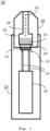
- Fig. 1 shows a heating generation device 10 configured to receive a cartridge 20 suitable for containing a vaporizable material 21, wherein the heating generation device 10 comprises a cartridge connector arranged to receive a cartridge 20.
- the heating generation device 10 further comprises a heating element 11 arranged to transfer heat to the vaporizable material 21.
- the heating element 11 may be a resistive heater.
- the resistive heater may be provided as a set of resistive tracks embedded in a ceramic material.
- the cartridge connector may hold in place the cartridge 20 in place using magnets, a plug-in connection, a screw connection, or the like.
- the heating element 11 is however not restricted to a resistive heater, as in fact the invention functions also with any other type of heater that requires electrical power as provided by the electrical conductors.
- the cartridge connector is an arrangement that allows the cartridge to be coupled with the device 10, and includes -by way of example and without any limitation - any arrangement that allows a mechanical coupling between the cartridge into the device (e.g., by thread and screw; by means of a recess and production, each correspondingly provided in the cartridge and device; etc.), an electrical and/or magnetic coupling between the same (e.g., by using magnets, etc.) or any combination thereof.
- the heating generation device 10 may preferably form an aerosol generation system 30, wherein the cartridge 20 is suitable for containing the vaporizable material 21 and preferably comprises a membrane 23 adapted to transfer heat to the vaporizable material 21 to vaporize it.
- the membrane is an arrangement that allows transfer of heat from the heater to the vaporizable material and is preferably configured to confine the material in a respective reservoir and/or separate the vaporizable material from the heater and/or other components of the device.
- the membrane may be a thin element such as a thin metal sheet.
- the membrane 23 of the cartridge 20 When a cartridge 20 is inserted into the heating generation device 10, heat from the heating element 11 may be transferred to the vaporizable material 21 via the membrane 23 of the cartridge 20 that may be in contact with the heating element 11.
- a surface (in one example, the membrane 23) of the cartridge 20 may be brought into direct contact with the heating element 11, thereby allowing heat to be conducted from the heating element 11 to the cartridge 20 in order to heat and vaporize at least a portion of the vaporizable material 21 contained therein.
- the membrane 23 may be a surface of the heater and/or cartridge facing the heating element, a separate element that transfers heat to the material or a combination of these.
- the vaporizable material 21 is a material suitable for generating vapor when the material is heated.
- the vaporizable material 21 may be a liquid and/or a gel. In some other examples, the vaporizable material 21 is solid.
- the vaporizable material 21 may contain tobacco and/or other additives such as aromatics. When the vaporizable material 21 is vaporized, an aerosol 22 may be generated that may be inhaled by a user of the heating generation device 10.
- the cartridge 20 may comprise a vaporization chamber 24 in which the aerosol 22 is generated, a vapor conduit 25 through which the aerosol 22 is ejected from the vaporization chamber 24, and a mouthpiece by which the user can inhale the ejected aerosol 22, for example, by performing suction on the mouthpiece.
- the cartridge 20 may be a consumable article that can be ejected from the cartridge 20, for example after the vaporizable material 21 therein is depleted. Thereafter, a new cartridge 20 may be inserted. In this manner, the user is not required to handle the vaporizable material 21 directly but may instead replace a depleted cartridge 20 by replacing it with a new one. In other examples, the cartridge 20 is refillable.
- the heating generation device further comprises electrical conductors 12 configured to provide power to the heating element 11, wherein the electrical conductors 12 comprise a thermal decoupler.
- Power may be provided by a power supply 14 included in the heating generation device 10.
- the power supply 14 may be a battery.
- the electrical conductors 12 may be pair of wires connected to the power supply 14.
- the heating generation device 10 may further comprise a control unit for controlling the power supply 14.
- the electrical conductors 12 may contact the heating element 11 via the thermal decoupler 13.
- the thermal decoupler 13 may be arranged to provide a sufficient amount of power to the heating element 11 from the power supply 14 in order to vaporize the vaporizable material 21 in the cartridge 20.
- the contact of the thermal decoupler 13 with the heating element 11 allows current to flow from the power supply 14 to the heating element 11, thereby heating the heating element 11.
- the current provided through the thermal decoupler 13 to the heating element 11 is comprised between 2 and 5 amperes.
- the present disclosure is applicable also to the case of one electrical conductor connected to the power supply: in this case, the return path of the electric current may occur via a ground connection, the ground connection being for example realized on one region of the heating generation device that enters into contact with the cartridge when the cartridge is received in the device. Such ground connection may then be connected to the power supply.
- the electrical conductors are realized in one single component: for example, one electric internal conductor is surrounded by an insulating sheath, which is in turn wound by another external conductor (representing for example the ground); in this example, the internal and external conductors can be seen as one single element representing the electrical conductors.
- the herein disclosed solution also if described with reference to a plurality of electrical conductors, is equally applicable with at least one electrical conductor. In other words, the description with reference to a plurality of conductors equally applies to the case of one conductor.
- thermal decoupler 13 may refer to structural features of the electrical conductors 12, the type of connection between the heating element 11 and the electrical conductors 12, and/or to a mechanism (preferably a user-activated mechanism) of establishing contact between the heating element 11 and the electrical conductors 12.
- Structural features of the electrical conductors 12 may refer to a shape, material composition and/or internal construction of at least a part of the electrical conductors 12 that is in proximity or in contact with the heating element 12.
- thermal decoupling may be achieved by a peaked shape of the electrical conductors 12 that reduces a contacting area.
- the thermal decoupling may be achieved by a material composition of the electrical conductors 12 comprising compounds, such as a titanium alloy and/or vanadium dioxide, which have relatively low thermal conductivity and relatively high electrical conductivity.
- the thermal decoupling may be achieved by a porous internal structure of the electrical conductors 12.
- the type of connection between the heating element 11 and the electrical conductors 12 may relate to a manner in which energy is transferred from the power supply 14 to the heating element 11.
- the thermal decoupling may be achieved with a direct physical contact such that a closed electrical circuit may be formed between the power supply 14 and the heating element 11.
- the thermal decoupling may be achieved by inductive coupling between the electrical conductors 12 (conducting AC power) and the heating element 11, wherein electrical energy is transferred by means of a first coil formed by the electrical conductors 12 and a second coil comprised by the heating element 11, and wherein the gap between the first coil and the second coil provides thermal decoupling of the heating element 11 from the rest of the hardware of the heating generation device 10.
- the (preferably user-activated) mechanism of establishing contact between the heating element 11 and the electrical conductors 12 may refer to means of connecting and disconnecting the electrical conductors 12 to and from the heating element 11 preferably in response to an operation performed by a user of the heating generation device 10.
- the user-activated mechanism may be coupled to a button of the heating generation device 10. When the user presses the button the electrical conductors 12 are pushed against the heating element 11 via the user-activated mechanism, thereby allowing current to flow from the power supply 14 to the heating element 11. When the button is not pressed, the electrical conductors 12 are not in contact with the heating element 11, thereby providing thermal decoupling of the heating element 11 from the rest of the hardware of the heating generation device 10.
- the mechanism of establishing contact may be activated automatically upon inserting the cartridge 20 into the heating generation device 10.
- the user may control operations of the heating generation device using an interface such as one or more buttons on the outside of the heating generation device. For example, the user may press a button to control the heating generation device to provide power to the heating element 11 in order to generate the aerosol 22.
- the thermal decoupler 13 may be arranged to minimize an amount of heat conducted away from the heating element 11 by the electrical conductors 12. In other words, the amount of heat transferred from the heating element 11 through the electrical conductors 12 to the rest of the hardware of the heating generation device 10 may be reduced compared to the case wherein the electrical conductors are directly connected to the heating element without intervention of the thermal decoupler. In this manner, unwanted heat conduction that does not directly contribute to heating the vaporizable material 21 is reduced, i.e., heat transfer to the vaporizable material is maximized since dispersion of heat towards the electrical conductors is minimized.
- the heating efficiency of the heating generation device 10 may be improved. In this manner, less energy may be required to vaporize the vaporizable material 21. For a handheld embodiment of the heating generation device 10, the reduction of unwanted heat conduction may enable a longer operation time of the heating generation device 10 and higher comfort for the user holding the heating generation device 10.
- the thermal decoupler 13 may be arranged to minimize a contacting area between the electrical conductors 12 and the heating element 11. By reducing the contacting area, the amount of heat that can be conducted from the heating element 11 through the contacting area to the electrical conductors 12 may be reduced. It is possible to reduce the contacting area to a minimum size that is significantly smaller than a diameter of the electrical conductors 12 while still being large enough to allow provision of sufficient power to the heating element 11 for vaporizing the vaporizable material 21. For example, an operating current of the heating element 11 may be between 2 and 5 amperes, which may be achieved without excessive electrical dissipation while minimizing thermal dispersion.
- the thermal decoupler 13 may be provided by tips of the electrical conductors 12 contacting the heating element 11, wherein the tips have a cross-section that progressively decreases towards the heating element 11, wherein preferably the tips have a conic shape.
- the electrical conductors 12 may be pencil-shaped, wherein the pointy end may be in contact with the heating element 11.
- the tips of the electrical conductors 12 may be domed, wherein the heating element 11 may be tangent to the surface of the domed tips.
- the lower diameter of the electrical conductors 12 at the tip compared may result in a smaller contacting area, thereby reducing the unwanted heat conduction that does not directly contribute to heating the vaporizable material 21.
- the thermal decoupler 13 may comprise one or more spring-loaded pins. Such spring-loaded pins may commonly be referred to as pogo-pins.
- the spring-loaded pins may comprise a helical spring that applies a constant normal force against the heating element 11, thereby counteracting any unwanted movement which might otherwise cause an interruption in the electrical connection.
- the electrical contact may be highly resilient to mechanical shock and vibration.
- the pin head of each of the one or more spring-loaded pins may be domed, thereby minimizing the contacting area between the electrical conductors 12 and the heating element 11.
- Fig. 2A shows a cross-sectional view of the heating element 11 and the electrical conductors 12 including a pair of spring-loaded pins as the thermal decoupler 13.
- the thermal decoupler 13 may comprise one or more clip-in connectors.
- each of the clip-in connectors may be regarded as a mating connector comprising a male part and a female part.
- the male part may be provided as a metal pin or sheet.
- the female part may be provided by harness assembly such as a metal cuff or clamp for holding the male part inserted thereinto in place.
- the tips of the electrical conductors 12 may be the male part and the female part may be mounted on the heating element 11. In this manner, the clip-in connector may provide a secure connection between the heating element 11 and the electrical conductors 12.
- Fig. 2B shows a cross-sectional view of the heating element 11 and the electrical conductors 12 including a pair of clip-in connectors as the thermal decoupler 13.
- the thermal decoupler 13 may comprise one or more cantilever connectors.
- each of the cantilever connectors be provided a bendable piece of metal extending from the tip of an electrical conductor. The bendable piece of metal may press against the heating element 11, thereby ensuring a stable electrical connection.
- Fig. 2C shows a cross-sectional view of the heating element 11 and the electrical conductors 12 including a pair of cantilever connectors as the thermal decoupler 13.
- the heating element 11 may be removably integrated into the heating generation device 10.
- the heating element 11 may be held in place using magnets, a plug-in connection, a screw connection, or the like. In this manner, the user may easily replace the heating element 11 in case of a failure.
- each of the above-described embodiments for the thermal decoupler 13 spring-loaded pins, clip-in connectors, cantilever connectors
- the heating element 11 may be arranged between the thermal decoupler 13 and a cartridge 20 inserted into the cartridge connector. In other words, the heating element 11 is sandwiched between the inserted cartridge 20 and the thermal decoupler 13. Heat generated in the heating element 11 may then predominantly be transferred towards the cartridge 20.
- the surface of the cartridge 20 that is in contact with the heating element 11 may be provided as a membrane 23, wherein the heat from the heating element 11 is transferred to the vaporizable material 21 via the membrane 23.
- the thermal decoupler 13 may further be arranged to connect the electrical conductors 12 to the heating element 11, when a cartridge 20 is inserted into the cartridge connector, and to disconnect the electrical conductors 12 from the heating element 11, when a cartridge 20 is ejected from the cartridge connector; this configuration may also be named “floating heater” embodiment.
- a "floating heater” of the heating generation device 10 allows the heating element 11 to come into contact with the electrical contacts only when the cartridge 20 is inserted. Thus, only after the cartridge 20 is inserted into the device, the heating element 11 is pushed against the electrical conductors 12 and an electrical connection established. Otherwise, the heating element 11 is not in contact with the electrical conductors 12.
- the heating generation device 10 provides a fail-safe mechanism by which a potential leakage of current through the heating device may be prevented when no cartridge 20 is inserted and no heating is required.
- the thermal decoupler 13 may be configured to exert pressure toward the heating element 11 to abut it against a surface of the cartridge 20 when the cartridge 20 is inserted into the cartridge connector. In this manner, the heating element 11 may be ensured to have stable electrical contact with the electrical conductors 12, when the cartridge 20 is inserted. For example, such configuration may enhance electrical contact (i.e., contribute to achieve low resistivity), hence achieving low electrical dissipation while reducing or minimizing heat dissipation.
- the thermal decoupler 13 may be configured to provide thermal decoupling between the heating element 11 and the electrical conductors 12 while the heating element 11 is heating. In this manner, the amount of heat transferred from the heating element 11 through the electrical conductors 12 to the rest of the hardware of the heating generation device 10 may be reduced even when power is provided to heating element 11 during the heating of the vaporizable material 21.
- Fig. 3A shows a perspective view of a heating element 11 (not visible) and electrical conductors 12 according to an embodiment of the present invention
- Fig. 3B shows a corresponding cross-sectional view of the heating element 11, the electrical conductors 12 and the thermal decoupler 13.
- Fig. 4 shows another cross-sectional view of the heating element 11, the electrical conductors 12 and the thermal decoupler 13.
- the components shown in Fig. 3A, 3B and 4 are suitable for reducing the amount of heat conducted away from the heating element to the rest of the device's hardware, thereby improving the energy efficiency of the heating generation device.
Landscapes
- Resistance Heating (AREA)
Priority Applications (1)
| Application Number | Priority Date | Filing Date | Title |
|---|---|---|---|
| EP23175560.4A EP4467019A1 (de) | 2023-05-26 | 2023-05-26 | Wärmeerzeugungsvorrichtung mit wärmeentkoppler |
Applications Claiming Priority (1)
| Application Number | Priority Date | Filing Date | Title |
|---|---|---|---|
| EP23175560.4A EP4467019A1 (de) | 2023-05-26 | 2023-05-26 | Wärmeerzeugungsvorrichtung mit wärmeentkoppler |
Publications (1)
| Publication Number | Publication Date |
|---|---|
| EP4467019A1 true EP4467019A1 (de) | 2024-11-27 |
Family
ID=86605082
Family Applications (1)
| Application Number | Title | Priority Date | Filing Date |
|---|---|---|---|
| EP23175560.4A Withdrawn EP4467019A1 (de) | 2023-05-26 | 2023-05-26 | Wärmeerzeugungsvorrichtung mit wärmeentkoppler |
Country Status (1)
| Country | Link |
|---|---|
| EP (1) | EP4467019A1 (de) |
Citations (1)
| Publication number | Priority date | Publication date | Assignee | Title |
|---|---|---|---|---|
| US20190373953A1 (en) * | 2018-06-07 | 2019-12-12 | Juul Labs, Inc. | Cartridges for Vaporizer Devices |
-
2023
- 2023-05-26 EP EP23175560.4A patent/EP4467019A1/de not_active Withdrawn
Patent Citations (1)
| Publication number | Priority date | Publication date | Assignee | Title |
|---|---|---|---|---|
| US20190373953A1 (en) * | 2018-06-07 | 2019-12-12 | Juul Labs, Inc. | Cartridges for Vaporizer Devices |
Similar Documents
| Publication | Publication Date | Title |
|---|---|---|
| US20240398006A1 (en) | Bonding for an electronic cigarette cartridge | |
| US11672280B2 (en) | Heater assembly for cigarette-shaped electronic cigarette and cigarette-shaped electronic cigarette including same | |
| RU2643415C2 (ru) | Электронная система образования пара | |
| ES2836687T3 (es) | Sistema electrónico de suministro de vapor | |
| US20170117654A1 (en) | Electronic cigarette connector | |
| CN212488479U (zh) | 一种加热组件及气溶胶生成装置 | |
| US9826619B2 (en) | Electrode-supporting assembly for contact-start plasma arc torch | |
| US10238764B2 (en) | Aromatherapy vaporization device | |
| US11304443B2 (en) | Vaporizer heating assembly | |
| EP4410130A1 (de) | Aerosolerzeuger | |
| CN120304582A (zh) | 电加热发烟系统 | |
| KR20190089272A (ko) | 순간 가열이 가능한 궐련형 전자담배 기기 | |
| KR102051205B1 (ko) | 궐련형 전자담배 기기 | |
| CN214509413U (zh) | 一种烟弹及雾化装置 | |
| CN210642436U (zh) | 带转接组件的电子烟 | |
| EP4171283A2 (de) | Vorrichtung zum erwärmen von aerosolfähigem material | |
| CN216568381U (zh) | 气溶胶产生装置 | |
| CN207040873U (zh) | 电子烟以及电子烟连接组件 | |
| CN215501333U (zh) | 雾化装置 | |
| CN212212685U (zh) | 发热组件、雾化器及电子雾化装置 | |
| CN222780894U (zh) | 一种可通配多类雾化器的电子烟 | |
| KR102634967B1 (ko) | 차량용 터미널 | |
| CN220756563U (zh) | 一种气溶胶生成装置 | |
| CN218831998U (zh) | 气雾生成装置、充电装置及电系统 | |
| CN216568371U (zh) | 雾化器、主机及气溶胶产生装置 |
Legal Events
| Date | Code | Title | Description |
|---|---|---|---|
| PUAI | Public reference made under article 153(3) epc to a published international application that has entered the european phase |
Free format text: ORIGINAL CODE: 0009012 |
|
| STAA | Information on the status of an ep patent application or granted ep patent |
Free format text: STATUS: THE APPLICATION HAS BEEN PUBLISHED |
|
| AK | Designated contracting states |
Kind code of ref document: A1 Designated state(s): AL AT BE BG CH CY CZ DE DK EE ES FI FR GB GR HR HU IE IS IT LI LT LU LV MC ME MK MT NL NO PL PT RO RS SE SI SK SM TR |
|
| STAA | Information on the status of an ep patent application or granted ep patent |
Free format text: STATUS: THE APPLICATION IS DEEMED TO BE WITHDRAWN |
|
| 18D | Application deemed to be withdrawn |
Effective date: 20250528 |