EP4467040A1 - Appareil de cuisine, élément de connexion et procédé de transmission d'un signal d'informations - Google Patents
Appareil de cuisine, élément de connexion et procédé de transmission d'un signal d'informations Download PDFInfo
- Publication number
- EP4467040A1 EP4467040A1 EP23175358.3A EP23175358A EP4467040A1 EP 4467040 A1 EP4467040 A1 EP 4467040A1 EP 23175358 A EP23175358 A EP 23175358A EP 4467040 A1 EP4467040 A1 EP 4467040A1
- Authority
- EP
- European Patent Office
- Prior art keywords
- communication
- connecting element
- kitchen appliance
- module
- designed
- Prior art date
- Legal status (The legal status is an assumption and is not a legal conclusion. Google has not performed a legal analysis and makes no representation as to the accuracy of the status listed.)
- Pending
Links
Images





Classifications
-
- A—HUMAN NECESSITIES
- A47—FURNITURE; DOMESTIC ARTICLES OR APPLIANCES; COFFEE MILLS; SPICE MILLS; SUCTION CLEANERS IN GENERAL
- A47J—KITCHEN EQUIPMENT; COFFEE MILLS; SPICE MILLS; APPARATUS FOR MAKING BEVERAGES
- A47J36/00—Parts, details or accessories of cooking-vessels
- A47J36/32—Time-controlled igniting mechanisms or alarm devices
- A47J36/321—Time-controlled igniting mechanisms or alarm devices the electronic control being performed over a network, e.g. by means of a handheld device
-
- A—HUMAN NECESSITIES
- A47—FURNITURE; DOMESTIC ARTICLES OR APPLIANCES; COFFEE MILLS; SPICE MILLS; SUCTION CLEANERS IN GENERAL
- A47J—KITCHEN EQUIPMENT; COFFEE MILLS; SPICE MILLS; APPARATUS FOR MAKING BEVERAGES
- A47J43/00—Implements for preparing or holding food, not provided for in other groups of this subclass
- A47J43/04—Machines for domestic use not covered elsewhere, e.g. for grinding, mixing, stirring, kneading, emulsifying, whipping or beating foodstuffs, e.g. power-driven
- A47J43/07—Parts or details, e.g. mixing tools, whipping tools
- A47J43/0727—Mixing bowls
-
- A—HUMAN NECESSITIES
- A47—FURNITURE; DOMESTIC ARTICLES OR APPLIANCES; COFFEE MILLS; SPICE MILLS; SUCTION CLEANERS IN GENERAL
- A47J—KITCHEN EQUIPMENT; COFFEE MILLS; SPICE MILLS; APPARATUS FOR MAKING BEVERAGES
- A47J43/00—Implements for preparing or holding food, not provided for in other groups of this subclass
- A47J43/04—Machines for domestic use not covered elsewhere, e.g. for grinding, mixing, stirring, kneading, emulsifying, whipping or beating foodstuffs, e.g. power-driven
- A47J43/07—Parts or details, e.g. mixing tools, whipping tools
-
- A—HUMAN NECESSITIES
- A47—FURNITURE; DOMESTIC ARTICLES OR APPLIANCES; COFFEE MILLS; SPICE MILLS; SUCTION CLEANERS IN GENERAL
- A47J—KITCHEN EQUIPMENT; COFFEE MILLS; SPICE MILLS; APPARATUS FOR MAKING BEVERAGES
- A47J43/00—Implements for preparing or holding food, not provided for in other groups of this subclass
- A47J43/04—Machines for domestic use not covered elsewhere, e.g. for grinding, mixing, stirring, kneading, emulsifying, whipping or beating foodstuffs, e.g. power-driven
- A47J43/046—Machines for domestic use not covered elsewhere, e.g. for grinding, mixing, stirring, kneading, emulsifying, whipping or beating foodstuffs, e.g. power-driven with tools driven from the bottom side
-
- A—HUMAN NECESSITIES
- A47—FURNITURE; DOMESTIC ARTICLES OR APPLIANCES; COFFEE MILLS; SPICE MILLS; SUCTION CLEANERS IN GENERAL
- A47J—KITCHEN EQUIPMENT; COFFEE MILLS; SPICE MILLS; APPARATUS FOR MAKING BEVERAGES
- A47J43/00—Implements for preparing or holding food, not provided for in other groups of this subclass
- A47J43/04—Machines for domestic use not covered elsewhere, e.g. for grinding, mixing, stirring, kneading, emulsifying, whipping or beating foodstuffs, e.g. power-driven
- A47J43/07—Parts or details, e.g. mixing tools, whipping tools
- A47J43/0716—Parts or details, e.g. mixing tools, whipping tools for machines with tools driven from the lower side
-
- H—ELECTRICITY
- H04—ELECTRIC COMMUNICATION TECHNIQUE
- H04W—WIRELESS COMMUNICATION NETWORKS
- H04W4/00—Services specially adapted for wireless communication networks; Facilities therefor
- H04W4/80—Services using short range communication, e.g. near-field communication [NFC], radio-frequency identification [RFID] or low energy communication
-
- H—ELECTRICITY
- H04—ELECTRIC COMMUNICATION TECHNIQUE
- H04B—TRANSMISSION
- H04B7/00—Radio transmission systems, i.e. using radiation field
- H04B7/14—Relay systems
- H04B7/15—Active relay systems
- H04B7/155—Ground-based stations
- H04B7/15507—Relay station based processing for cell extension or control of coverage area
Definitions
- the present invention relates to a kitchen appliance with a base unit, the base unit having a first communication module designed for wireless communication, with a receptacle, the receptacle having a wall with a penetrating opening, and with an accessory, the accessory having a second communication module designed for wireless communication.
- the invention also relates to a connecting element for a kitchen appliance with a base body, the base body being at least partially designed for arrangement in a penetrating opening in the wall of a receptacle of the kitchen appliance. A method for transmitting an information signal is also described.
- the basic device In order to keep the manufacturing costs of these accessories low and thus increase the profitability of the accessories business, the basic device should be versatile and contain as many of the more expensive components as possible, such as the electric motor for driving the moving parts of the accessories or a control device.
- the basic device In order to keep the manufacturing costs of these accessories low and thus increase the profitability of the accessories business, the basic device should be versatile and contain as many of the more expensive components as possible, such as the electric motor for driving the moving parts of the accessories or a control device.
- NFC transponder Near Field Communication Transponder
- the present invention is based on the object of improving previously known kitchen appliances, in particular to increase the user-friendliness when inserting accessories.
- a kitchen appliance with a base unit, wherein the base unit has a first communication module designed for wireless communication, with a receptacle, wherein the receptacle has a wall with a penetrating opening, and with an accessory, wherein the accessory has a second communication module designed for wireless communication, in that a connecting element is provided, wherein the connecting element is designed for arrangement in the penetrating opening of the wall of the receptacle, and wherein the connecting element is designed for transmitting signals between the first communication module and the second communication module.
- the invention makes it easy to convert existing kitchen appliances and at the same time increase user-friendliness.
- a basic device in the sense of the present invention is preferably designed as a basis for the use of a receptacle and accessories.
- the basic device has a housing in which an electric motor for driving accessories is arranged.
- the receptacle has a wall that at least partially surrounds a receiving space for receiving food.
- the wall preferably comprises a base and walls that are designed as one piece or multiple pieces, as separate parts.
- a handle or a double base can be attached to the wall, for example.
- a heater can be provided on the base.
- the handle or the double base can be made of a thermally insulating material in order to reduce the risk of burns for a user or a kitchen work surface.
- the wall or the base of the receptacle or the double base can be designed in such a way that it forms an interface for mechanical connection to the housing of the basic device.
- the wall of the receptacle has a penetrating opening.
- the penetrating opening is formed in the bottom, in particular if the receptacle is intended for connection to the base unit in the bottom area.
- the penetrating opening can be formed on a wall of the wall. In this case, the requirements for tightness with respect to foodstuffs stored in the receiving space of the receptacle are lower, and thus the manufacture of the kitchen appliance is simpler.
- An accessory is understood to be any part designed to work together with the basic device.
- the term "work together” includes, among other things, the actions from the list: connecting, coupling, assembling, putting on, attaching, applying and the like.
- an accessory is designed to expand the function of the basic device, for example as a cutting, stirring, cooking, weighing, roasting, steaming or covering unit.
- the basic device and the accessory each have a communication module set up for wireless communication.
- the first communication module of the basic device and the second communication module of the accessory are preferably set up to exchange signals with each other wirelessly.
- the first communication module is set up to emit an excitation signal, for example a high-frequency electromagnetic alternating field, and to receive and evaluate a modulated response signal.
- the second communication module is preferably set up to modulate an excitation signal of the first communication module and output it as a modulated response signal.
- a connecting element in the sense of the present invention is an element that is suitable for ensuring a communication connection between the accessory and the base unit. It is provided that the connecting element is designed to be arranged in the penetrating opening of the wall of the receptacle. In this way, the connecting element can transmit a signal, in particular in the form of an electromagnetic wave, that has been emitted by the first communication module of the base unit on one side of the wall, through the wall and forward it to the second communication module of the accessory. This also applies in the opposite direction, i.e. for a signal transmitted from the second communication module of the accessory towards the first communication module of the base unit.
- the connecting element preferably has a base body with a shape that is at least partially adapted to the shape of the penetrating opening.
- a sealing element can be provided between the base body of the connecting element and the inner wall of the opening.
- the connecting element can have a cap that helps to seal the opening when the connecting element is mounted in the penetrating opening of the wall of the receptacle.
- the cap is preferably made of a material that is resistant to mechanical stresses that occur during food preparation in the receptacle and that is at least partially permeable to electromagnetic waves. Examples of such materials are polymer materials, silicone, ceramic or a combination thereof.
- the wall of the receptacle is at least partially made of a material that is at least partially impermeable to electromagnetic waves.
- the permeability of a material to electromagnetic waves or fields depends on the conductivity and permeability of the material as well as on the frequency of the waves or field.
- stainless steel is essentially impermeable or predominantly attenuates these waves.
- stainless steel has proven to be essentially impermeable to electromagnetic waves with a frequency of approximately 13.56 MHz.
- the essentially impermeable nature of the material was tested on areas of the wall of the receptacle that do not have a penetrating opening.
- the material is also preferably suitable for hygienically, especially at elevated temperatures, which regularly occur during food preparation.
- the connecting element has a first communication element and a second communication element, wherein the first communication element is configured for wireless communication with the first communication module of the base unit and the second communication element is configured for wireless communication with the second communication module of the accessory, and wherein the first communication element and the second communication element are connected via a cable connection.
- the size of the penetrating opening in the wall of the receptacle can be kept small in order to ensure a higher tightness of the receptacle.
- the first communication element and the second communication element can be designed simply and inexpensively in this way, whereby a signal can be reliably transmitted from one to the other.
- the first communication module of the base unit is a near-field communication reading module, in particular an RFID (Radio-Frequency Identification) reading module or an NFC (Near Field Communication) reading module
- the second communication module of the accessory is a near-field communication transponder, in particular an RFID transponder or an NFC transponder
- the first communication element, the second communication element and their connection form a passive near-field repeater module, in particular an RFID repeater module or an NFC repeater module.
- RFID transceivers So-called RFID transceivers, transponders and repeaters are freely available on the market, simple, cost-effective to manufacture and robust in application.
- Corresponding NFC modules are also available. They also offer a signal transmission range that is suitable for kitchen appliances of this type.
- the RFID or NFC transponder can be designed to be passive or active.
- NFC near field communication
- RFID radio frequency identification
- the connecting element has a base body with a first distal section, with a transition section and with a second distal section, wherein the first distal section and the second distal section are arranged in opposite directions and the transition section connects the first distal section and the second distal section, wherein the transition section is designed for arrangement in the penetrating opening in the wall of the receiving vessel.
- the first communication element is arranged on the first distal section and the second communication element is arranged on the second distal section.
- the first communication element and the second communication element can each be arranged on one side of the wall of the receptacle.
- the obstacle that a receptacle made of a shielding material forms can thus be overcome for a signal exchange.
- signals can then be transmitted between the first communication module of the basic device and the second communication module of the accessory. without the signals being redirected around the wall of the receptacle, for example via the handle or the lid.
- the adjective “distal” is preferably to be understood as “away from the center of the base body”.
- the transition section forms a transition between the first distal section and the second distal section.
- the first distal section, the transition section and the second distal section can be formed in one piece, for example in the form of a shaft or a transmission element with a force transmission profile, in particular with a screw drive profile. This makes it easier to design the connection between the first communication element and the second communication element.
- the transition section has a cable guide and the cable guide guides the cable connection between the first communication element and the second communication element.
- the cable guide can be a channel, for example a bore, that passes through the transition section from the first distal section to the second distal section of the base body of the connecting element.
- This design of the cable guide enables a sealed connection between the two communication elements of the connecting element, which is electrically insulated from its surroundings and thus reliable and durable.
- the cable guide can be a recess in an outer surface of a component of the connecting element, which is provided for receiving the cable connection.
- the recess extends from the position of the first communication element to the position of the second communication element.
- the recess, which is accommodated in the cable connection can be filled with an insulating material. The Insulating material thus seals the recess with the cable connection or electrically insulates the cable connection from the environment.
- the cable connection has a coaxial conductor.
- the connecting element or the base body of the connecting element at least partially comprises an electrically conductive material and the coaxial conductor is at least partially formed by the electrically conductive material of the base body of the connecting element.
- the connecting element can be made more compact, in particular a separate cable can be dispensed with.
- the base unit has a drive and the connecting element or the base body of the connecting element is designed to transmit a driving force from the drive of the base unit to the accessory.
- a connecting element which is already provided for driving the accessory in a kitchen appliance of this type, can be easily replaced or retrofitted in order to connect the base unit to the accessory both mechanically and in terms of signaling. It is particularly advantageous that the base unit, the accessory and the receptacle of kitchen appliances already available on the market can continue to be used unchanged and only the connecting element needs to be replaced.
- a connecting element can, for example, have a first distal section in the form of a transmission element with a screw drive profile for connection to the drive of the base unit, a second distal section in the form of an interface element for a mechanical connection to an accessory and a transition section in the form of a shaft that carries a blade unit.
- the first communication element may be a coil on the interface element and the second communication element may be a coil on the transmission element.
- a connecting element for a kitchen appliance with a base body wherein the base body is at least partially designed for arrangement in a penetrating opening in the wall of a receptacle of the kitchen appliance, in that a first communication element configured for wireless communication and a second communication element configured for wireless communication are provided, and that the first communication element and the second communication element are connected via a cable connection.
- Such connecting elements are suitable for making kitchen appliances with a recognition system for accessories easier to design.
- the remaining parts of a kitchen appliance such as the receptacle, can be used unchanged compared to existing kitchen appliances.
- Existing kitchen appliances can also be easily retrofitted or converted using the connecting element.
- connecting element and its embodiments from the following paragraphs offer the same advantages as the kitchen system and the corresponding embodiments of the kitchen system.
- the first communication element, the second communication element and their connection form a passive near-field repeater module, in particular an RFID repeater module or an NFC repeater module.
- the base body has a first distal section, a transition section and a second distal section, wherein the first distal section and the second distal section are arranged in opposite directions and the transition section connects the first distal section and the second distal section, and wherein the transition section is designed for arrangement in the penetrating opening in the wall of a receptacle of the kitchen appliance.
- the first communication element is arranged on the first distal section and the second communication element is arranged on the second distal section.
- the transition section has a cable guide and the cable guide guides the cable connection between the first communication element and the second communication element.
- the cable connection has a coaxial conductor
- the base body has at least partially an electrically conductive material
- the coaxial conductor is at least partially formed by the electrically conductive material of the base body of the connecting element.
- the base body can have a shaft which is designed to transmit a driving force and with a composition comprising a metal.
- the base body has a transmission element for transmitting a driving force from the first distal section to the second distal section.
- the connecting element has a blade unit and the transmission element is for Transfer of a driving force from the drive of the base unit to the knife unit.
- both the blade unit and an accessory part that is mechanically compatible with the connecting element can be driven or set in motion by the drive of the basic device.
- the above-mentioned object is also achieved by a method for transmitting an information signal between a first communication module of a base unit of a kitchen appliance, which is set up for wireless communication, and a second communication module of an accessory part of the kitchen appliance, which is set up for wireless communication, in which a signal is transmitted between the first communication module and the second communication module by means of a connecting element according to one of the embodiments described above.
- the process also offers the same advantages as the kitchen appliance and the connecting element in the previous paragraphs.
- Fig. 1 shows kitchen appliance 2 with a base unit 4, with a receptacle 6, with an accessory 8 and with a connecting element 10.
- the base unit 4 has a housing 12, a drive 14 and a first communication module 16 in the form of an RFID transceiver, which is set up for wireless communication.
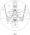
- the section Ia of the kitchen appliance is in Fig. 1a shown in further details.
- the receptacle 6 is designed to hold food or ingredients for carrying out a preparation process.
- the receptacle 6 is designed to hold liquids and hot ingredients and has a wall 18 made of stainless steel.
- the wall 18 is formed in one piece with side walls 20 and a base 22, wherein the wall 18 has an upper opening for holding food.
- a heater (not shown) for heating the food held is integrated in the base 22.
- the accessory part 8 is intended for use in the receiving space 24 of the receiving vessel 6 and to supplement the function of the kitchen appliance 2.
- the accessory part 8 can take the form of a stirring, cutting, peeling, weighing or covering unit, for example.
- the accessory part 8 has a second communication module 26 set up for wireless communication, here designed as an RFID transponder.
- the wall 18 of the receiving vessel 6 at least partially prevents the path of electromagnetic waves between both sides of the wall 18.
- the wall 18 of the Fig. 1 and Fig. 1a shown receiving vessel 6 has a penetrating opening 28 in which the connecting element 10 is received.
- the connecting element 10 has a base body 30 with a first distal section 32, with a transition section 34 and with a second distal section 36.
- the first distal section 32 and the second distal section 36 are arranged in opposite directions.
- the transition section 34 connects the first distal section 32 and the second distal section 36.
- the transition section 34 has an outer diameter d that is adapted to the inner diameter D of the penetrating opening 28 of the wall 18 of the receiving vessel 6.
- a cap 38 with a sealing element 40 is provided, which ensures a tight connection of the connecting element 10 to the wall 18 or the bottom 22 of the receiving vessel 6.
- the connecting element 10 has a first communication element 42 on the first distal section 32 and a second communication element 44 on the second distal section 36.
- the first communication element 42 is for wireless communication with the first communication module 16 of the basic device 4
- the second communication element 44 is set up for wireless communication with the second communication module 26 of the accessory 8.
- the first communication element 42 and the second communication element 44 are connected via a cable connection 46.
- the first communication element 42, the second communication element 44 and the cable connection 46 form a passive RFID repeater module which is suitable for transmitting a signal between the first communication module 16 of the basic device 4 and the second communication module 26 of the accessory 8.
- Fig. 2 shows a first example of a connecting element 50, which is designed with a blade unit 52, with a sealing cap 54 and with a base body 56 in the form of a transmission element 57.
- the transmission element 57 is in turn designed as a shaft.
- the connecting element 50 has a first distal section 58, a second distal section 60 and a transition section 62 connecting these sections 58, 60.
- the connecting element 50 has a first communication element 64 and a second communication element 66, which are each arranged on the first distal section 58 and the second distal section 60. Both communication elements 64, 66 are set up for signal transmission with further NFC elements or modules using NFC technology.
- the first communication element 64 and the second communication element 66 are connected via a cable connection 68, which is arranged in a cable guide 70 designed as a hole through the transmission element 57.
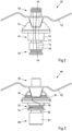
- Fig. 3 shows a second example of a connecting element 80, which is also designed with a blade unit 82, with a sealing cap 84 and with a base body 86 in the form of a transmission element 87.
- the sealing cap 84 is intended to withstand the mechanical stresses occurring during a preparation process and at the same time to protect against electromagnetic waves be at least partially permeable.
- the sealing cap 84 is essentially made of plastic.
- the connecting element 80 has a first distal section 88, a second distal section 90 and a transition section 92.
- a first NFC communication element 94 and a second NFC communication element 96 are provided, which are connected by means of a cable connection 98.
- the first communication element 94 and the second communication element 96 are arranged closer to each other and at the transition section 92.
- the second communication element 96 is arranged behind the blade unit 82 and the sealing cap 84, as viewed from the second distal portion 90. This enables better manufacturability of the connecting element 80.
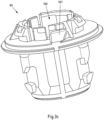
- Fig. 3a , Fig. 3b , Fig. 3c and Fig. 3d show a component 99 of the connecting element 80 from the Fig. 3
- the component 99 is designed as a knife bearing holder and has a central, penetrating opening 100 which is designed to accommodate a shaft.
- Fig. 3a and 3c is the component 99 in a first perspective view and in the Fig. 3b and 3D shown in a second perspective view.
- Fig. 3a and 3b Component 99 without insulation material, while the Fig. 3c and 3D show component 99 with insulation material.
- the first NFC communication element 94 is arranged at a first end 101 of the component 99.
- the first NFC communication element 94 is connected via the cable connection 98 to the second NFC communication element 96, which is arranged at a second end 102 of the component 99.
- the cable connection 98 is designed as a cable 103 with a capacitor PCB 104, wherein both the cable 103 and the capacitor PCB 104 are each arranged in a recess 105a, 105b in the mass of the component 99.
- the cable connection 98 and the recesses 105a, 105b together extend from the first end 101 to the second end 102 of the component 99.
- the first NFC communication element 94 and the second NFC communication element 96 are each embedded in recesses 106a, 106b in the mass of the component 99.
- insulating material 107 here silicone, was applied by a so-called “over-molding" process, so that the first NFC communication element 94, the second NFC communication element 96, the cable connection 98 and their connections are electrically insulated from the environment and protected against mechanical stress.
- Fig. 4 shows a third example of a connecting element 110, which has a blade unit 112, a sealing cap 114 and a base body 116 in the form of a transmission element 117.
- the transmission element 117 is designed as a shaft with a first distal section 118 and a second distal section 120, wherein the first distal section 118 of the transmission element 117 is simultaneously the first distal section of the connecting element 110. This also applies to the second distal section 120 of the transmission element 117 or the connecting element 110.
- a first communication element 122 is arranged on the first distal section 118 and a second communication element 124 is arranged on the second distal section 120.
- the transmission element has a core 128 made of an electrically insulating material that runs along the main extension axis 126 of the transmission element 117 and a wall 130 made of an electrically conductive material that runs around the core 128.
- a cable connection 132 runs through the core 128. Both the wall 130 of the transmission element 117 and the cable connection 132 are connected to both communication elements 122, 124, so that the wall 130 of the transmission element 117 and the cable connection 132 together form a coaxial conductor between the first and second communication elements 122, 124.
- Fig. 5 shows a second example of a kitchen appliance 140 with a connecting element 142.
- the kitchen appliance 140 has a base unit 144, which has a first communication module 146 set up for wireless communication, a receptacle 148 with a wall 150 and an accessory 152, wherein the accessory 152 has a second communication module 154 set up for wireless communication.
- a penetrating opening 158 is provided in a side wall 156 of the wall 150 of the receptacle 148.
- the connecting element 142 is designed as a repeater module or for signal transmission between the first and second communication modules 146, 154 and is arranged in the penetrating opening 158 of the wall 150.
Landscapes
- Engineering & Computer Science (AREA)
- Food Science & Technology (AREA)
- Mechanical Engineering (AREA)
- Computer Networks & Wireless Communication (AREA)
- Signal Processing (AREA)
- Cookers (AREA)
Priority Applications (3)
| Application Number | Priority Date | Filing Date | Title |
|---|---|---|---|
| EP23175358.3A EP4467040A1 (fr) | 2023-05-25 | 2023-05-25 | Appareil de cuisine, élément de connexion et procédé de transmission d'un signal d'informations |
| US18/673,543 US20240389800A1 (en) | 2023-05-25 | 2024-05-24 | Kitchen Appliance, Connecting Element and Method for Transmitting an Information Signal |
| CN202410651427.1A CN119014729A (zh) | 2023-05-25 | 2024-05-24 | 厨房设备、连接元件和用于传输信息信号的方法 |
Applications Claiming Priority (1)
| Application Number | Priority Date | Filing Date | Title |
|---|---|---|---|
| EP23175358.3A EP4467040A1 (fr) | 2023-05-25 | 2023-05-25 | Appareil de cuisine, élément de connexion et procédé de transmission d'un signal d'informations |
Publications (1)
| Publication Number | Publication Date |
|---|---|
| EP4467040A1 true EP4467040A1 (fr) | 2024-11-27 |
Family
ID=86603703
Family Applications (1)
| Application Number | Title | Priority Date | Filing Date |
|---|---|---|---|
| EP23175358.3A Pending EP4467040A1 (fr) | 2023-05-25 | 2023-05-25 | Appareil de cuisine, élément de connexion et procédé de transmission d'un signal d'informations |
Country Status (3)
| Country | Link |
|---|---|
| US (1) | US20240389800A1 (fr) |
| EP (1) | EP4467040A1 (fr) |
| CN (1) | CN119014729A (fr) |
Citations (3)
| Publication number | Priority date | Publication date | Assignee | Title |
|---|---|---|---|---|
| EP3056882A1 (fr) * | 2015-02-13 | 2016-08-17 | Vorwerk & Co. Interholding GmbH | Procédé de mesure d'une température dans un appareil de cuisine |
| WO2021038528A1 (fr) * | 2019-08-30 | 2021-03-04 | Apption Labs Limited | Dispositifs de détection de température et perfectionnements de communication sans fil apportés à des appareils de cuisson |
| EP3841926A1 (fr) | 2019-12-23 | 2021-06-30 | Vorwerk & Co. Interholding GmbH | Élément fonctionnel pour un appareil de cuisine, appareil de cuisine et procédé de communication de données |
-
2023
- 2023-05-25 EP EP23175358.3A patent/EP4467040A1/fr active Pending
-
2024
- 2024-05-24 US US18/673,543 patent/US20240389800A1/en active Pending
- 2024-05-24 CN CN202410651427.1A patent/CN119014729A/zh active Pending
Patent Citations (3)
| Publication number | Priority date | Publication date | Assignee | Title |
|---|---|---|---|---|
| EP3056882A1 (fr) * | 2015-02-13 | 2016-08-17 | Vorwerk & Co. Interholding GmbH | Procédé de mesure d'une température dans un appareil de cuisine |
| WO2021038528A1 (fr) * | 2019-08-30 | 2021-03-04 | Apption Labs Limited | Dispositifs de détection de température et perfectionnements de communication sans fil apportés à des appareils de cuisson |
| EP3841926A1 (fr) | 2019-12-23 | 2021-06-30 | Vorwerk & Co. Interholding GmbH | Élément fonctionnel pour un appareil de cuisine, appareil de cuisine et procédé de communication de données |
Also Published As
| Publication number | Publication date |
|---|---|
| CN119014729A (zh) | 2024-11-26 |
| US20240389800A1 (en) | 2024-11-28 |
Similar Documents
| Publication | Publication Date | Title |
|---|---|---|
| DE102010055511B4 (de) | Elektronikmodul für eine temperaturüberwachte Zubereitung von Gargut in einem Kochgefäß | |
| EP3153080B1 (fr) | Robot menager electrique | |
| DE102007042042B4 (de) | Verfahren zur Ermittlung und Überwachung des Füllstands eines Mediums in einem Behälter nach einem Laufzeitmessverfahren | |
| DE19641036C2 (de) | Mit Mikrowellen arbeitendes Füllstandsmeßgerät | |
| DE69111993T2 (de) | Ultraschallsonde und Linsenanordnung dazu. | |
| EP3814730B1 (fr) | Élément de remplissage diélectrique d'étanchéité à élément renforcé mécaniquement | |
| DE69009587T2 (de) | Ringförmige Fühleranordnung. | |
| EP0706825A1 (fr) | Porte-échantillons pour le sang, l'urine, ou pareil, avec porteur de données | |
| EP1070517A3 (fr) | Emetteur pour l'unité de télémétrie d'un implant | |
| EP3338598B1 (fr) | Recipient de cuisson pour robot menager, robot menager et procédé de fabrication d'un 'élément chauffant | |
| DE102006050344A1 (de) | Aufnahmebehälter mit RFID-Etikett | |
| DE112005002125T5 (de) | Radarfüllstandsmessgerät mit Schalter zum Auswählen einer Sende- oder Empfangs-Betriebsart | |
| DE4421373A1 (de) | Ofen zur Wärmebehandlung von stückförmigen Lebensmitteln | |
| EP3052276B1 (fr) | Couteau pourvu d'un transpondeur rfid disposé sur une soie | |
| DE102009047418A1 (de) | Messvorrichtung zur Erfassung einer Temperatur im Inneren eines Garguts, Einrichtung für ein Hausgerät zum Zubereiten von Lebensmitteln mit einer derartigen Messvorrichtung sowie Hausgerät zum Zubereiten von Lebensmitteln und Verfahren zum Betreiben einer Messvorrichtung | |
| WO2020064262A1 (fr) | Ustensile de cuisson pour une plaque de cuisson à induction et système de cuisson | |
| EP3841926B1 (fr) | Élément fonctionnel pour un appareil de cuisine, appareil de cuisine et procédé de communication de données | |
| EP4467040A1 (fr) | Appareil de cuisine, élément de connexion et procédé de transmission d'un signal d'informations | |
| DE102005023468B4 (de) | Gargerät | |
| EP3763325A1 (fr) | Cassette destinée à stocker au moins un instrument médical ou dentaire dans un appareil de nettoyage ou de soin | |
| DE19828170A1 (de) | Kochgeschirr für intelligente Herde | |
| EP3856071B1 (fr) | Pièce à main dentaire ou chirurgicale dotée d'un transpondeur rfid | |
| DE102014111644A1 (de) | Vorrichtung zur Bestimmung des Füllstands eines Füllguts | |
| DE1448264A1 (de) | Hohlraumresonator fuer gyromagnetische Messungen,insbesondere mit Temperaturregelung | |
| EP4467041A1 (fr) | Récipient de réception pour un appareil de cuisine, appareil de cuisine et procédé de fonctionnement d'un appareil de cuisine |
Legal Events
| Date | Code | Title | Description |
|---|---|---|---|
| PUAI | Public reference made under article 153(3) epc to a published international application that has entered the european phase |
Free format text: ORIGINAL CODE: 0009012 |
|
| STAA | Information on the status of an ep patent application or granted ep patent |
Free format text: STATUS: THE APPLICATION HAS BEEN PUBLISHED |
|
| AK | Designated contracting states |
Kind code of ref document: A1 Designated state(s): AL AT BE BG CH CY CZ DE DK EE ES FI FR GB GR HR HU IE IS IT LI LT LU LV MC ME MK MT NL NO PL PT RO RS SE SI SK SM TR |
|
| STAA | Information on the status of an ep patent application or granted ep patent |
Free format text: STATUS: REQUEST FOR EXAMINATION WAS MADE |
|
| 17P | Request for examination filed |
Effective date: 20250526 |
|
| GRAP | Despatch of communication of intention to grant a patent |
Free format text: ORIGINAL CODE: EPIDOSNIGR1 |
|
| STAA | Information on the status of an ep patent application or granted ep patent |
Free format text: STATUS: GRANT OF PATENT IS INTENDED |
|
| RIC1 | Information provided on ipc code assigned before grant |
Ipc: A47J 36/32 20060101AFI20251210BHEP |
|
| INTG | Intention to grant announced |
Effective date: 20251223 |
|
| GRAS | Grant fee paid |
Free format text: ORIGINAL CODE: EPIDOSNIGR3 |
|
| GRAA | (expected) grant |
Free format text: ORIGINAL CODE: 0009210 |
|
| STAA | Information on the status of an ep patent application or granted ep patent |
Free format text: STATUS: THE PATENT HAS BEEN GRANTED |