EP4467092A1 - Endeffektor mit länglichem trägerelement mit gekrümmtem elektrodenlandebereich - Google Patents
Endeffektor mit länglichem trägerelement mit gekrümmtem elektrodenlandebereich Download PDFInfo
- Publication number
- EP4467092A1 EP4467092A1 EP24177203.7A EP24177203A EP4467092A1 EP 4467092 A1 EP4467092 A1 EP 4467092A1 EP 24177203 A EP24177203 A EP 24177203A EP 4467092 A1 EP4467092 A1 EP 4467092A1
- Authority
- EP
- European Patent Office
- Prior art keywords
- extension
- end effector
- electrode
- landing region
- longitudinal axis
- Prior art date
- Legal status (The legal status is an assumption and is not a legal conclusion. Google has not performed a legal analysis and makes no representation as to the accuracy of the status listed.)
- Pending
Links
Images



Classifications
-
- A—HUMAN NECESSITIES
- A61—MEDICAL OR VETERINARY SCIENCE; HYGIENE
- A61B—DIAGNOSIS; SURGERY; IDENTIFICATION
- A61B18/00—Surgical instruments, devices or methods for transferring non-mechanical forms of energy to or from the body
-
- A—HUMAN NECESSITIES
- A61—MEDICAL OR VETERINARY SCIENCE; HYGIENE
- A61B—DIAGNOSIS; SURGERY; IDENTIFICATION
- A61B18/00—Surgical instruments, devices or methods for transferring non-mechanical forms of energy to or from the body
- A61B18/04—Surgical instruments, devices or methods for transferring non-mechanical forms of energy to or from the body by heating
- A61B18/12—Surgical instruments, devices or methods for transferring non-mechanical forms of energy to or from the body by heating by passing a current through the tissue to be heated, e.g. high-frequency current
- A61B18/14—Probes or electrodes therefor
-
- A—HUMAN NECESSITIES
- A61—MEDICAL OR VETERINARY SCIENCE; HYGIENE
- A61B—DIAGNOSIS; SURGERY; IDENTIFICATION
- A61B18/00—Surgical instruments, devices or methods for transferring non-mechanical forms of energy to or from the body
- A61B18/04—Surgical instruments, devices or methods for transferring non-mechanical forms of energy to or from the body by heating
- A61B18/12—Surgical instruments, devices or methods for transferring non-mechanical forms of energy to or from the body by heating by passing a current through the tissue to be heated, e.g. high-frequency current
- A61B18/14—Probes or electrodes therefor
- A61B18/1492—Probes or electrodes therefor having a flexible, catheter-like structure, e.g. for heart ablation
-
- A—HUMAN NECESSITIES
- A61—MEDICAL OR VETERINARY SCIENCE; HYGIENE
- A61B—DIAGNOSIS; SURGERY; IDENTIFICATION
- A61B34/00—Computer-aided surgery; Manipulators or robots specially adapted for use in surgery
- A61B34/20—Surgical navigation systems; Devices for tracking or guiding surgical instruments, e.g. for frameless stereotaxis
-
- A—HUMAN NECESSITIES
- A61—MEDICAL OR VETERINARY SCIENCE; HYGIENE
- A61B—DIAGNOSIS; SURGERY; IDENTIFICATION
- A61B5/00—Measuring for diagnostic purposes; Identification of persons
- A61B5/68—Arrangements of detecting, measuring or recording means, e.g. sensors, in relation to patient
- A61B5/6846—Arrangements of detecting, measuring or recording means, e.g. sensors, in relation to patient specially adapted to be brought in contact with an internal body part, i.e. invasive
- A61B5/6847—Arrangements of detecting, measuring or recording means, e.g. sensors, in relation to patient specially adapted to be brought in contact with an internal body part, i.e. invasive mounted on an invasive device
- A61B5/6852—Catheters
- A61B5/6858—Catheters with a distal basket, e.g. expandable basket
-
- A—HUMAN NECESSITIES
- A61—MEDICAL OR VETERINARY SCIENCE; HYGIENE
- A61B—DIAGNOSIS; SURGERY; IDENTIFICATION
- A61B18/00—Surgical instruments, devices or methods for transferring non-mechanical forms of energy to or from the body
- A61B2018/00053—Mechanical features of the instrument of device
- A61B2018/00059—Material properties
- A61B2018/00071—Electrical conductivity
- A61B2018/00083—Electrical conductivity low, i.e. electrically insulating
-
- A—HUMAN NECESSITIES
- A61—MEDICAL OR VETERINARY SCIENCE; HYGIENE
- A61B—DIAGNOSIS; SURGERY; IDENTIFICATION
- A61B18/00—Surgical instruments, devices or methods for transferring non-mechanical forms of energy to or from the body
- A61B2018/00053—Mechanical features of the instrument of device
- A61B2018/0016—Energy applicators arranged in a two- or three dimensional array
-
- A—HUMAN NECESSITIES
- A61—MEDICAL OR VETERINARY SCIENCE; HYGIENE
- A61B—DIAGNOSIS; SURGERY; IDENTIFICATION
- A61B18/00—Surgical instruments, devices or methods for transferring non-mechanical forms of energy to or from the body
- A61B2018/00053—Mechanical features of the instrument of device
- A61B2018/00214—Expandable means emitting energy, e.g. by elements carried thereon
- A61B2018/00267—Expandable means emitting energy, e.g. by elements carried thereon having a basket shaped structure
-
- A—HUMAN NECESSITIES
- A61—MEDICAL OR VETERINARY SCIENCE; HYGIENE
- A61B—DIAGNOSIS; SURGERY; IDENTIFICATION
- A61B18/00—Surgical instruments, devices or methods for transferring non-mechanical forms of energy to or from the body
- A61B2018/00315—Surgical instruments, devices or methods for transferring non-mechanical forms of energy to or from the body for treatment of particular body parts
- A61B2018/00345—Vascular system
- A61B2018/00351—Heart
-
- A—HUMAN NECESSITIES
- A61—MEDICAL OR VETERINARY SCIENCE; HYGIENE
- A61B—DIAGNOSIS; SURGERY; IDENTIFICATION
- A61B18/00—Surgical instruments, devices or methods for transferring non-mechanical forms of energy to or from the body
- A61B2018/00315—Surgical instruments, devices or methods for transferring non-mechanical forms of energy to or from the body for treatment of particular body parts
- A61B2018/00345—Vascular system
- A61B2018/00351—Heart
- A61B2018/00357—Endocardium
-
- A—HUMAN NECESSITIES
- A61—MEDICAL OR VETERINARY SCIENCE; HYGIENE
- A61B—DIAGNOSIS; SURGERY; IDENTIFICATION
- A61B18/00—Surgical instruments, devices or methods for transferring non-mechanical forms of energy to or from the body
- A61B2018/00571—Surgical instruments, devices or methods for transferring non-mechanical forms of energy to or from the body for achieving a particular surgical effect
- A61B2018/00577—Ablation
-
- A—HUMAN NECESSITIES
- A61—MEDICAL OR VETERINARY SCIENCE; HYGIENE
- A61B—DIAGNOSIS; SURGERY; IDENTIFICATION
- A61B18/00—Surgical instruments, devices or methods for transferring non-mechanical forms of energy to or from the body
- A61B2018/00571—Surgical instruments, devices or methods for transferring non-mechanical forms of energy to or from the body for achieving a particular surgical effect
- A61B2018/00601—Cutting
-
- A—HUMAN NECESSITIES
- A61—MEDICAL OR VETERINARY SCIENCE; HYGIENE
- A61B—DIAGNOSIS; SURGERY; IDENTIFICATION
- A61B18/00—Surgical instruments, devices or methods for transferring non-mechanical forms of energy to or from the body
- A61B2018/00571—Surgical instruments, devices or methods for transferring non-mechanical forms of energy to or from the body for achieving a particular surgical effect
- A61B2018/00613—Irreversible electroporation
-
- A—HUMAN NECESSITIES
- A61—MEDICAL OR VETERINARY SCIENCE; HYGIENE
- A61B—DIAGNOSIS; SURGERY; IDENTIFICATION
- A61B18/00—Surgical instruments, devices or methods for transferring non-mechanical forms of energy to or from the body
- A61B2018/00636—Sensing and controlling the application of energy
- A61B2018/00773—Sensed parameters
- A61B2018/00827—Current
-
- A—HUMAN NECESSITIES
- A61—MEDICAL OR VETERINARY SCIENCE; HYGIENE
- A61B—DIAGNOSIS; SURGERY; IDENTIFICATION
- A61B18/00—Surgical instruments, devices or methods for transferring non-mechanical forms of energy to or from the body
- A61B2018/00636—Sensing and controlling the application of energy
- A61B2018/00773—Sensed parameters
- A61B2018/00839—Bioelectrical parameters, e.g. ECG, EEG
-
- A—HUMAN NECESSITIES
- A61—MEDICAL OR VETERINARY SCIENCE; HYGIENE
- A61B—DIAGNOSIS; SURGERY; IDENTIFICATION
- A61B18/00—Surgical instruments, devices or methods for transferring non-mechanical forms of energy to or from the body
- A61B2018/00636—Sensing and controlling the application of energy
- A61B2018/00773—Sensed parameters
- A61B2018/00875—Resistance or impedance
-
- A—HUMAN NECESSITIES
- A61—MEDICAL OR VETERINARY SCIENCE; HYGIENE
- A61B—DIAGNOSIS; SURGERY; IDENTIFICATION
- A61B18/00—Surgical instruments, devices or methods for transferring non-mechanical forms of energy to or from the body
- A61B2018/00636—Sensing and controlling the application of energy
- A61B2018/00773—Sensed parameters
- A61B2018/00892—Voltage
-
- A—HUMAN NECESSITIES
- A61—MEDICAL OR VETERINARY SCIENCE; HYGIENE
- A61B—DIAGNOSIS; SURGERY; IDENTIFICATION
- A61B18/00—Surgical instruments, devices or methods for transferring non-mechanical forms of energy to or from the body
- A61B18/04—Surgical instruments, devices or methods for transferring non-mechanical forms of energy to or from the body by heating
- A61B18/12—Surgical instruments, devices or methods for transferring non-mechanical forms of energy to or from the body by heating by passing a current through the tissue to be heated, e.g. high-frequency current
- A61B18/14—Probes or electrodes therefor
- A61B2018/1467—Probes or electrodes therefor using more than two electrodes on a single probe
-
- A—HUMAN NECESSITIES
- A61—MEDICAL OR VETERINARY SCIENCE; HYGIENE
- A61B—DIAGNOSIS; SURGERY; IDENTIFICATION
- A61B34/00—Computer-aided surgery; Manipulators or robots specially adapted for use in surgery
- A61B34/20—Surgical navigation systems; Devices for tracking or guiding surgical instruments, e.g. for frameless stereotaxis
- A61B2034/2046—Tracking techniques
- A61B2034/2051—Electromagnetic tracking systems
Definitions
- the present invention generally relates to medical instruments, and more particular to end effectors for medical probes capable of magnetic position sensing and ablation.
- Cardiac arrhythmias such as atrial fibrillation (AF) occur when regions of cardiac tissue abnormally conduct electrical signals to adjacent tissue. This disrupts the normal cardiac cycle and causes asynchronous rhythm. Certain procedures exist for treating arrhythmia, including surgically disrupting the origin of the signals causing the arrhythmia and disrupting the conducting pathway for such signals. By selectively ablating cardiac tissue by application of energy via a catheter, it is sometimes possible to cease or modify the propagation of unwanted electrical signals from one portion of the heart to another.
- AF atrial fibrillation
- RF ablation can have certain risks related to thermal heating which can lead to tissue charring, burning, steam pop, phrenic nerve palsy, pulmonary vein stenosis, and esophageal fistula.
- IRE irreversible electroporation
- Some ablation approaches use irreversible electroporation (IRE) to ablate cardiac tissue using nonthermal ablation methods.
- IRE delivers short pulses of high voltage to tissues and generates an unrecoverable permeabilization of cell membranes. Delivery of IRE energy to tissues using multi-electrode catheters was previously proposed in the patent literature.
- Examples of systems and devices configured for IRE ablation are disclosed in U.S. Patent No. 11,540,877 and U.S. Patent Pub. No. 2021/0169550A1 , 2021/0177503A1 , and 2021/0186604A1 , each of which are incorporated herein by reference and attached in the Appendix of parent Patent Application No. 63/503,754 .
- Further examples of IRE systems are disclosed in 2021/0169567A1 , 2021/0169568A1 , 2021/0196372A1 , each of which are incorporated herein by reference.
- a magnetic field can be sensed by positioning a conductive coil in the magnetic field and observing electrical current and/or voltage induced in the coil by a change in the magnetic field that is aligned with an axis of the conductive coil. Because electrical current is induced in the conductive coil, such a coil is also referred to as an inductive coil. Relative position of a sensor including one or more inductive coils can be determined in relation to a known magnetic field source by monitoring the induced electric current and/or voltage.
- Navigation sensors which include three coil arrangements aligned along three orthogonal axes to determine position and orientation of the navigation sensor in three dimensions within a known induced magnetic field are disclosed for instance in U.S. Patent Numbers 10,330,742 and 10,677,857 , each included by reference as if set forth herein and attached in the Appendix of parent Patent Application No. 63/503,754 .
- Integrating a navigation sensor into a catheter suitable for intravascular and/or intracardiac treatments can involve crafting the sensor by hand, which can result in significant manufacturing time and labor costs.
- Navigation sensor components can account for a significant percentage of catheter material costs.
- an end effector of a medical probe can include a plurality of elongated support members extending along a longitudinal axis of the end effector.
- the plurality of elongated support members can be configured to expand from the longitudinal axis.
- Each of the plurality of elongated support members can include an electrode landing region.
- the electrode landing region of each of the plurality of elongated support members can include a first surface facing away from the longitudinal axis.
- the electrode landing region of each of the plurality of elongated support members can also include at least one extension extending from the first surface and curving toward the longitudinal axis.
- the first surface of the electrode landing region can also include an electrode coupled to the first surface.
- the end effector can include an inductive coil coupled to at least one extension.
- the plurality of elongated support members can be coupled to each other at a proximal end of the end effector and at a distal end of the end effector.
- the electrode landing region can comprise a contiguous outer surface such that the contiguous outer surface comprises the first surface and a curved outer surface of each extension of the at least one extension and such that a portion of the curved outer surface of each extension of the at least one extension faces the longitudinal axis.
- the contiguous outer surface can comprise a P-shaped or B-shaped profile.
- the at least one extension can include further curving to overlap a portion of a second surface of the electrode landing region, the second surface facing toward the longitudinal axis and opposite the first surface.
- the at least one extension can also include being folded at least 180°.
- the end effector can further include the at least one extension having a pair of extensions symmetrically extending on either side of the electrode landing region.
- the end effector can also include the at least one extension being folded such that an end of the at least on extension approaches a second surface of the electrode landing region, the second surface facing toward the longitudinal axis and opposite the first surface.
- the end effector can also include the at least one extension forming a pocket across a portion of a second surface of the electrode landing region, the second surface facing toward the longitudinal axis and opposite the first surface.
- the end effector can also include an electrical component having a portion positioned within the pocket.
- the electrical component can also include an inductive coil such that a portion of the inductive coil is positioned within the pocket.
- the inductive coil can also comprise an insulated wire strand wound about an axis of the inductive coil.
- the axis of the inductive coil can include being parallel to the longitudinal axis.
- the axis of the inductive coil can include being orthogonal to the first surface.
- the end effector can include further having an inductive coil coupled to the at least one extension such that the inductive coil spirals about a sensor axis orthogonal to the longitudinal axis and parallel to the first surface.
- the end effector can include further having a flex circuit coupled to the first surface of the electrode landing region and having an electrode metallization layer parallel to the first surface and exposed to ambient environment.
- the flex circuit can further include being coupled to the at least one extension.
- the flex circuit can further include having an inductive coil coupled to the at least one extension and curving toward the longitudinal axis parallel to the at least one extension.
- the end effector can include further having an insulated wire coupled to the flex circuit and in electrical communication with the electrode metallization layer, the insulated wire being positioned facing a second surface of the electrode landing region, the second surface facing toward the longitudinal axis and opposite the first surface.
- the end effector can further include the elongated support member having a substantially uniform thickness over a majority of the length of the end effector.
- the end effector can also include the elongate support member being formed from a substantially planar sheet cut such that the electrode landing region comprises a first width, a distal extension extending distally from the electrode landing region comprises a second width less than the first width, and a proximal extension extending distally from the electrode landing region comprises a third width less than the first width and approximately equal to the second width.
- a method of manufacture for an end effector can include: cutting a planar sheet to form an elongated support member having an electrode landing region having at least one extension that extends orthogonally from an axis of the elongated support member; curving the at least one extension such that a central portion of the electrode landing region comprises a first planar surface and a second planar surface opposite the first planar surface and such the at least one extension curves away from the first planar surface; and coupling an electrode to the first planar surface.
- the method can further include coupling an electrode to at least one of the at least one extension.
- the method can further include curving the at least one extension to overlap at least a portion of the second planar surface.
- the method can further include forming a recess with the at least one extension, the recess being across a portion of the second planar surface or approximate the second planar surface.
- the method can also include positioning a portion of an inductive coil within the recess.
- the method can further include positioning an inductive coil approximate the second planar surface and curving the at least one extension over the inductive coil.
- the axis of the inductive coil can include being parallel to a longitudinal axis of the elongated support member. The axis of the inductive coil can also include being orthogonal to the first surface.
- the at least one extension can include having a pair of extensions extending symmetrically from a central body of the elongated support member. In some examples, wherein curving the at least one extension can comprise curving each extension of the pair of extensions away from the first planar surface to form symmetrical curves.
- the method can further include coupling a flex circuit to the first surface of the electrode landing region such that an electrode metallization layer of the flex circuit is parallel to the first surface and exposed to ambient environment.
- the method can also include coupling the flex circuit to the at least one extension.
- the method can also include the flex circuit having an inductive coil and coupling the flex circuit to the at least one extension can include positioning the inductive coil across a surface of the at least one extension.
- the method can further include coupling an insulated wire to the flex circuit.
- the method can further include positioning an insulated jacket over at least a portion of the electrode landing region.
- curving the at least one extension can comprise folding the at least one extension at least 180°. Curving the at least one extension can also comprise folding the at least one extension such that an end of the at least on extension approaches the second planar surface.
- an end effector can include an elongated support member extending along a longitudinal axis.
- the end effector can also include an electrode landing pad coupled to the elongated support member such that the electrode landing pad is folded around the elongated support member to provide an outer surface and two side surfaces on opposite sides of the outer surface.
- the end effector can also include a flex circuit having an electrode metallization layer, the flex circuit being coupled to the outer surface of the electrode landing pad, and the electrode metallization layer being parallel to the outer surface and exposed to ambient environment.
- the end effector can also include an insulated wire in electrical communication with the electrode metallization layer, the insulated wire being positioned in a recess formed by the elongated support member and/or the electrode landing pad.
- the end effector can include further having a pair of parallel elongated support members having the elongated support member extending along the longitudinal axis forming a gap between elongated support members of the pair of elongated support members, the gap having the recess in which the insulated wire is positioned.
- the end effector can also include the recess being positioned approximate an end of the electrode landing pad and approximate an inner surface of the elongated support member.
- the flex circuit can include being confined to the outer surface of the electrode landing pad.
- the flex circuit can include extending over at least a portion of at least one of the two side surfaces of the electrode landing pad.
- the end effector can further include an inductive coil disposed in the recess.
- the terms “about” or “approximately” for any numerical values or ranges indicate a suitable dimensional tolerance that allows the part or collection of components to function for its intended purpose as described herein. More specifically, “about” or “approximately” may refer to the range of values ⁇ 20% of the recited value, e.g. "about 90%” may refer to the range of values from 71% to 99%.
- microcatheter is a catheter having a diameter that is small in comparison to catheters in cardiovascular applications, i.e. 8 French or less.
- tubular and tube are to be construed broadly and are not limited to a structure that is a right cylinder or strictly circumferential in cross-section or of a uniform cross-section throughout its length.
- a tubular structure or system is generally illustrated as a substantially right cylindrical structure.
- the tubular system may have a tapered or curved outer surface without departing from the scope of the present disclosure.
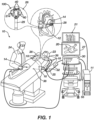
- FIG. 1 is an illustration showing an example catheter-based electrophysiology mapping and ablation system 10.
- the system 10 includes multiple catheters, which are percutaneously inserted by a physician 24 through the patient's vascular system into a chamber or vascular structure of a heart 12.
- a delivery sheath catheter is inserted into the left or right atrium near a desired location in the heart 12.
- a plurality of catheters can be inserted into the delivery sheath catheter so as to arrive at the desired location.
- the plurality of catheters may include catheters dedicated for sensing Intracardiac Electrogram (IEGM) signals, catheters dedicated for ablating and/or catheters dedicated for both sensing and ablating.
- An example catheter 14 that is configured for sensing IEGM is illustrated herein.
- the physician 24 brings a distal tip 28 of the catheter 14 into contact with the heart wall for sensing a target site in the heart 12. For ablation, the physician 24 would similarly bring a distal end of an ablation catheter to a target site for ablating
- the illustrated catheter 14 is an exemplary catheter that includes one and preferably multiple electrodes 26 optionally distributed over a plurality of spines 22 at distal tip 28 and configured to sense the IEGM signals.
- Catheter 14 may additionally include a position sensor 29 embedded in or near distal tip 28 for tracking position and orientation of distal tip 28.
- position sensor 29 is a magnetic based position sensor including three magnetic coils for sensing three-dimensional (3D) position and orientation.
- a magnetic based position sensor 29 may be operated together with a location pad 25 including a plurality of magnetic coils 32 configured to generate magnetic fields in a predefined working volume. Real time position of a distal tip 28 of the catheter 14 may be tracked based on magnetic fields generated with a location pad 25 and sensed by a magnetic based position sensor 29. Details of the magnetic based position sensing technology are described in U.S. Patent Nos. 5,391,199 ; 5,443,489 ; 5,558,091 ; 6,172,499 ; 6,239,724 ; 6,332,089 ; 6,484,118 ; 6,618,612 ; 6,690,963 ; 6,788,967 ; 6,892,091 incorporated by reference herein.
- the end effector 100 can include one or more inductive coils 120 coupled to an inner side of the spines 214 under the electrodes 26 as illustrated in Figs. 3A, 3B , 4A, 4B , and Fig. 9A and otherwise disclosed elsewhere herein.
- These inductive coils can be configured as a single axis magnetic based position sensor.
- the coils may further be combined to provide three axis sensing.
- the end effector 100 can be modified to include compatible features of navigation sensors which include three coil arrangements aligned along three orthogonal axes to determine position and orientation of the navigation sensor in three dimensions disclosed for instance in U.S. Patent Numbers 10,330,742 and 10,677,857 , each included by reference as if set forth herein and attached in the Appendix of parent Patent Application No. 63/503,754 .
- the system 10 includes one or more electrode patches 38 positioned for skin contact on the patient 23 to establish location reference for location pad 25 as well as impedance-based tracking of electrodes 26.
- impedance-based tracking electrical current is directed toward electrodes 26 and sensed at electrode skin patches 38 so that the location of each electrode can be triangulated via the electrode patches 38. Details of the impedance-based location tracking technology are described in US Patent Nos. 7,536,218 ; 7,756,576 ; 7,848,787 ; 7,869,865 ; and 8,456,182 incorporated by reference herein.
- a recorder 11 displays electrograms 21 captured with body surface ECG electrodes 18 and intracardiac electrograms (IEGM) captured with electrodes 26 of the catheter 14.
- the recorder 11 may include pacing capability for pacing the heart rhythm and/or may be electrically connected to a standalone pacer.
- the system 10 can include an ablation energy generator 50 that is adapted to conduct ablative energy to one or more of electrodes at a distal tip of a catheter configured for ablating.
- Energy produced by the ablation energy generator 50 may include, but is not limited to, radiofrequency (RF) energy or pulsed-field ablation (PFA) energy, including monopolar or bipolar high-voltage DC pulses as may be used to effect irreversible electroporation (IRE), or combinations thereof.
- RF radiofrequency
- PFA pulsed-field ablation
- IRE irreversible electroporation
- the electrodes 26 may be configured to provide RF or IRE signals to tissue to perform ablation. PFA generates substantially less heat than RF and therefore does not require electrodes able to withstand temperatures of electrodes suitable for RF.
- the electrodes 26 can therefore be made thinner (e.g. flex circuit layer) for PFA applications.
- a patient interface unit (PIU) 30 is an interface configured to establish electrical communication between catheters, electrophysiological equipment, power supply and a workstation 55 for controlling operation of system 10.
- Electrophysiological equipment of the system 10 may include for example, multiple catheters, a location pad 25, body surface ECG electrodes 18, electrode patches 38, an ablation energy generator 50, and a recorder 11.
- the PIU 30 includes processing capability for implementing real-time computations of location of the catheters and for performing ECG calculations.
- the workstation 55 includes memory, processor unit with memory or storage with appropriate operating software loaded therein, and user interface capability.
- the workstation 55 can be configured to provide multiple functions, optionally including (1) modeling the endocardial anatomy in three-dimensions (3D) and rendering the model or an anatomical map 20 for display on a display device 27; (2) displaying on the display device 27 activation sequences (or other data) compiled from recorded electrograms 21 in representative visual indicia or imagery superimposed on the rendered anatomical map 20; (3) displaying real-time location and orientation of multiple catheters within the heart chamber; and (4) displaying on the display device 27 sites of interest such as places where ablation energy has been applied.
- One commercial product embodying elements of the system 10 is available as the CARTO TM 3 System, available from Biosense Webster, Inc., 31A Technology Drive, Irvine, CA 92618.
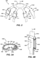
- FIG. 2 is an illustration of an end effector 100.
- the catheter 14 illustrated in FIG. 1 can be modified to include features of an end effector 100 illustrated in FIG. 2 .
- the end effector 100 can include a plurality of elongated support members 114a-d extending along a longitudinal axis 86 and coupled at a distal end 111 and a proximal end 112 of an end effector 100.
- the axis 121b of the inductive coil 120b can be orthogonal to the first surface 151.
- FIGS. 7A and 7B are illustrations of the dimensions of the elongate support member 114 of end effector 100.
- the elongate support member 114 can include a substantially uniform thickness T1 over a majority of the length of the end effector 100.
- the elongate support member can include an electrode landing region 150 having a first width W4 less than the first width W3 of FIGS. 7A-7B , a distal extension 116 extending distally from the electrode landing region 150 along the axis 88 of the elongate support member 114 and having a second width W1 less than the first width W3, and a proximal extension 117 extending proximally from the electrode landing region 150 and having a third width W2 less than the first width W4 and approximately equal to the second width W2.
- FIGS. 8B and 8C are illustrations of the dimensions of elongate support member 114 wherein the electrode landing extensions are curved toward the longitudinal axis 86 of the end effector 100.
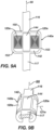
- FIGS. 9A and 9B are illustrations of an elongate member that can include an alternate electrode assembly 140e, similar to electrode assembly 140 described in FIG. 2 above.
- the elongate member can include a distal extension 116, a proximal extension 117, a first surface 151, a second surface 152, and an electrode landing region 150.
- the electrode landing region 150 can include at least one extension 153 positioned orthogonal to the longitudinal axis 88 of the elongate tubular member 114 and an electrode assembly 140e disposed thereon.
- the electrode assembly 140e can include a flex circuit 142 coupled to the electrode landing region 150 and the at least one extension 153 of the electrode landing region 150.
- the inductive coils 120e provide an additional axis for which to reference and measure the position of the catheter. This allows for simplified location and orientation of the catheter during operation.
- FIG. 10A is an illustration of an alternate electrode assembly 240a.
- the electrode assembly 240a can include an elongate support member 214a extending along a longitudinal axis 86, an electrode landing pad 230 coupled to the elongate support member 214a, a flex circuit 242a having an electrode metallization layer 244 and its top surface 246 coupled to the outer surface 231 of the electrode landing pad 230, and an insulated wire 262 in electrical communication with the electrode metallization layer 244 and positioned in a gap formed by the elongate support member 214a and/or the electrode landing pad 230.
- the electrode landing pad can be coupled to the elongate support member 214a such that the electrode landing pad is folded around the elongated support member 214a to provide an outer surface 231 and two side surfaces 232 on opposite sides of the outer surface 231.
- the electrode metallization layer 244 can be coupled to the outer surface 231 of the electrode landing pad 230 such that it is parallel to the outer surface 231 and exposed to ambient environment.
- elongate support member 214a can include a pair of parallel elongated support members 214a forming a gap 250a between the pair of elongated support members 214a, the gap 250a having the recess in which the insulated wire 262 is positioned.
- the gap 250a formed by the pair of elongated support members 214a can also include an inductive coil 220 disposed in the recess.
- FIG. 10B is an illustration of an alternate electrode assembly 240b.
- the electrode assembly 240b can include an elongate support member 214b extending along a longitudinal axis 86, an electrode landing pad 230 coupled to the elongate support member 214b, a flex circuit 242b having an electrode metallization layer 244, and an insulated wire 262 in electrical communication with the electrode metallization layer 244 and positioned in a gap formed by the elongate support member 214b and/or the electrode landing pad 230.
- the electrode landing pad 230 can be coupled to the elongate support member 214b such that the electrode landing pad 230 is folded around the elongated support member 214b to provide an outer surface 231 and two side surfaces 232 on opposite sides of the outer surface 231.
- the flex circuit 242b can be disposed over the outer surface 231 of the electrode landing pad.
- the flex circuit 242b can also extend over at least a portion of at least one of the two side surfaces 232 of the electrode landing pad 230.
- the electrode metallization layer 244 can be coupled to the outer surface 231 of the electrode landing pad 230 such that it is parallel to the outer surface 231 and exposed to ambient environment.
- elongate support member 214b can include a gap 250b positioned approximate an end of the electrode landing pad 230 and approximate an inner surface 245 of the elongated support member 214b.
- the gap 250b can also include an inductive coil 220 disposed within the gap 250b.
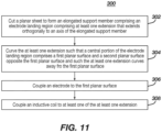
- FIG. 11 is a flow diagram of a method 300 for manufacturing an end effector 100 as disclosed herein.
- the method steps in FIG. 11 can be implemented by any of the example means described herein or by similar means, as will be appreciated.
- the resulting end effector 100 can be configured similarly to the example end effector 100 presented herein, variations therefore, and alternatives thereto as understood by a person skilled in the pertinent art.
- the method 300 can include cutting a planar sheet to form an elongated support member 114 having an electrode landing region 150 having at least one extension 153 that extends orthogonally to an axis of the elongated support member 114.
- the method 300 can further include coupling an electrode 40 to at least one of the at least one extension 153.
- the method 300 can include curving the at least one extension 153 such that a central portion of the electrode landing region 150 comprises a first planar surface 151 and a second planar surface 152 opposite the first planar surface 151 and such the at least one extension 153 curves away from the first planar surface 151.
- the at least one extension 153 can include a pair of extensions extending symmetrically from a central body of the elongated support member 114 wherein curving the at least one extension includes curving each extension 153 of the pair of extensions away from the first planar surface 151 to form symmetrical curves.
- curving the at least one extension 153 can include curving the at least one extension 153 at least 180°.
- curving the at least one extension 153 can include curving folding the at least one extension 153 such that an end of the at least one extension 153 approaches the second planar surface 152.
- the method 300 can further include curving the at least one extension 153 to overlap at least a portion of the second planar surface 152.
- the method 300 can further include forming a recess 154 with the at least one extension 153, the recess 154 being across a portion of the second planar surface 152 or approximate the second planar surface 152.
- the method 300 can also include positioning a portion of an inductive coil 120 within the recess 154.
- the method 300 can include positioning the axis 121 of the inductive coil 120 such that the axis 121 is parallel to a longitudinal axis 86 of the elongated support member 114.
- the method 300 can include positioning the axis 121 of the inductive coil 120 such that the axis 121 is orthogonal to the first planar surface 151.
- the method 300 can include coupling an electrode 40 to the first planar surface 151.
- the method 300 can further include coupling a flex circuit 142 to the at least one extension 153 and the first surface 151 of the electrode landing region 150 such that an electrode metallization layer 144 of the flex circuit 142 is parallel to the first surface 151 and exposed to ambient environment.
- the flex circuit 142 can include an inductive coil 120 positioned across a surface of the at least one extension 153.
- the flex circuit 142 can also include an insulted wire 162 coupled to the flex circuit 142.
- the method 300 can further include positioning an insulated jacket 160 over at least a portion of the electrode landing region 150.
- the method 300 can include coupling an inductive coil 120 to at least one of the at least one extension 153.
Landscapes
- Health & Medical Sciences (AREA)
- Life Sciences & Earth Sciences (AREA)
- Surgery (AREA)
- Engineering & Computer Science (AREA)
- Animal Behavior & Ethology (AREA)
- Veterinary Medicine (AREA)
- Biomedical Technology (AREA)
- Heart & Thoracic Surgery (AREA)
- Medical Informatics (AREA)
- Molecular Biology (AREA)
- Public Health (AREA)
- General Health & Medical Sciences (AREA)
- Nuclear Medicine, Radiotherapy & Molecular Imaging (AREA)
- Otolaryngology (AREA)
- Physics & Mathematics (AREA)
- Plasma & Fusion (AREA)
- Robotics (AREA)
- Cardiology (AREA)
- Biophysics (AREA)
- Pathology (AREA)
- Surgical Instruments (AREA)
- Measurement And Recording Of Electrical Phenomena And Electrical Characteristics Of The Living Body (AREA)
Applications Claiming Priority (2)
| Application Number | Priority Date | Filing Date | Title |
|---|---|---|---|
| US202363503754P | 2023-05-23 | 2023-05-23 | |
| US18/641,750 US20240390056A1 (en) | 2023-05-23 | 2024-04-22 | End effector having elongated support member with curved electrode landing region |
Publications (1)
| Publication Number | Publication Date |
|---|---|
| EP4467092A1 true EP4467092A1 (de) | 2024-11-27 |
Family
ID=91226934
Family Applications (1)
| Application Number | Title | Priority Date | Filing Date |
|---|---|---|---|
| EP24177203.7A Pending EP4467092A1 (de) | 2023-05-23 | 2024-05-22 | Endeffektor mit länglichem trägerelement mit gekrümmtem elektrodenlandebereich |
Country Status (5)
| Country | Link |
|---|---|
| US (1) | US20240390056A1 (de) |
| EP (1) | EP4467092A1 (de) |
| JP (1) | JP2024169374A (de) |
| CN (1) | CN119014963A (de) |
| IL (1) | IL312760A (de) |
Families Citing this family (1)
| Publication number | Priority date | Publication date | Assignee | Title |
|---|---|---|---|---|
| WO2024075034A1 (en) | 2022-10-05 | 2024-04-11 | Btl Medical Technologies S.R.O. | Pulsed field ablation device and method |
Citations (26)
| Publication number | Priority date | Publication date | Assignee | Title |
|---|---|---|---|---|
| US5391199A (en) | 1993-07-20 | 1995-02-21 | Biosense, Inc. | Apparatus and method for treating cardiac arrhythmias |
| US5558091A (en) | 1993-10-06 | 1996-09-24 | Biosense, Inc. | Magnetic determination of position and orientation |
| US6172499B1 (en) | 1999-10-29 | 2001-01-09 | Ascension Technology Corporation | Eddy current error-reduced AC magnetic position measurement system |
| US6239724B1 (en) | 1997-12-30 | 2001-05-29 | Remon Medical Technologies, Ltd. | System and method for telemetrically providing intrabody spatial position |
| US6332089B1 (en) | 1996-02-15 | 2001-12-18 | Biosense, Inc. | Medical procedures and apparatus using intrabody probes |
| US6484118B1 (en) | 2000-07-20 | 2002-11-19 | Biosense, Inc. | Electromagnetic position single axis system |
| US6618612B1 (en) | 1996-02-15 | 2003-09-09 | Biosense, Inc. | Independently positionable transducers for location system |
| US6690963B2 (en) | 1995-01-24 | 2004-02-10 | Biosense, Inc. | System for determining the location and orientation of an invasive medical instrument |
| US6892091B1 (en) | 2000-02-18 | 2005-05-10 | Biosense, Inc. | Catheter, method and apparatus for generating an electrical map of a chamber of the heart |
| US7536218B2 (en) | 2005-07-15 | 2009-05-19 | Biosense Webster, Inc. | Hybrid magnetic-based and impedance-based position sensing |
| US7756576B2 (en) | 2005-08-26 | 2010-07-13 | Biosense Webster, Inc. | Position sensing and detection of skin impedance |
| US7848787B2 (en) | 2005-07-08 | 2010-12-07 | Biosense Webster, Inc. | Relative impedance measurement |
| US7869865B2 (en) | 2005-01-07 | 2011-01-11 | Biosense Webster, Inc. | Current-based position sensing |
| US8456182B2 (en) | 2008-09-30 | 2013-06-04 | Biosense Webster, Inc. | Current localization tracker |
| US10330742B2 (en) | 2016-12-23 | 2019-06-25 | Biosense Webster (Israel) Ltd. | Triple axis sensor on a single layer printed circuit |
| US10677857B2 (en) | 2017-12-15 | 2020-06-09 | Biosense Webster (Israel) Ltd. | Three-axial sensor including six single-axis sensors |
| US20210015551A1 (en) * | 2019-07-17 | 2021-01-21 | Biosense Webster (Israel) Ltd. | Blooming leaflet catheter with high density electrode array |
| US20210169550A1 (en) | 2019-12-05 | 2021-06-10 | Biosense Webster (Israel) Ltd. | Generating and interleaving of irreversible-electroporation and radiofrequnecy ablation (ire/rfa) waveforms |
| US20210169567A1 (en) | 2019-12-09 | 2021-06-10 | Biosense Webster (Israel) Ltd. | Irreversible-electroporation (ire) balloon catheter with membrane-insulated high-voltage balloon wires |
| US20210169568A1 (en) | 2019-12-09 | 2021-06-10 | Biosense Webster (Israel) Ltd. | Oriented irreversible-electroporation (ire) pulses to compensate for cell size and orientation |
| US20210177503A1 (en) | 2019-12-11 | 2021-06-17 | Biosense Webster (Israel) Ltd. | Regulating delivery of irreversible electroporation pulses according to transferred energy |
| US20210186604A1 (en) | 2019-12-24 | 2021-06-24 | Biosense Webster (Israel) Ltd. | Irreversible electroporation (ire) based on field, contact force and time |
| US20210196372A1 (en) | 2019-12-31 | 2021-07-01 | Biosense Webster (Israel) Ltd. | Using irrigation on irreversible-electroporation (ire) electrodes to prevent arcing |
| US20220361942A1 (en) * | 2021-05-13 | 2022-11-17 | Biosense Webster (Israel) Ltd. | Distal Assembly for Catheter with Lumens Running Along Spines |
| US11540877B2 (en) | 2019-12-03 | 2023-01-03 | Biosense Webster (Israel) Ltd. | Pulse generator for irreversible electroporation |
| EP4393438A2 (de) * | 2022-12-30 | 2024-07-03 | Biosense Webster (Israel) Ltd. | Positions- und kraftsensoren für katheter |
-
2024
- 2024-04-22 US US18/641,750 patent/US20240390056A1/en active Pending
- 2024-05-09 IL IL312760A patent/IL312760A/en unknown
- 2024-05-22 CN CN202410637776.8A patent/CN119014963A/zh active Pending
- 2024-05-22 JP JP2024083227A patent/JP2024169374A/ja active Pending
- 2024-05-22 EP EP24177203.7A patent/EP4467092A1/de active Pending
Patent Citations (28)
| Publication number | Priority date | Publication date | Assignee | Title |
|---|---|---|---|---|
| US5391199A (en) | 1993-07-20 | 1995-02-21 | Biosense, Inc. | Apparatus and method for treating cardiac arrhythmias |
| US5443489A (en) | 1993-07-20 | 1995-08-22 | Biosense, Inc. | Apparatus and method for ablation |
| US5558091A (en) | 1993-10-06 | 1996-09-24 | Biosense, Inc. | Magnetic determination of position and orientation |
| US6690963B2 (en) | 1995-01-24 | 2004-02-10 | Biosense, Inc. | System for determining the location and orientation of an invasive medical instrument |
| US6332089B1 (en) | 1996-02-15 | 2001-12-18 | Biosense, Inc. | Medical procedures and apparatus using intrabody probes |
| US6618612B1 (en) | 1996-02-15 | 2003-09-09 | Biosense, Inc. | Independently positionable transducers for location system |
| US6788967B2 (en) | 1997-05-14 | 2004-09-07 | Biosense, Inc. | Medical diagnosis, treatment and imaging systems |
| US6239724B1 (en) | 1997-12-30 | 2001-05-29 | Remon Medical Technologies, Ltd. | System and method for telemetrically providing intrabody spatial position |
| US6172499B1 (en) | 1999-10-29 | 2001-01-09 | Ascension Technology Corporation | Eddy current error-reduced AC magnetic position measurement system |
| US6892091B1 (en) | 2000-02-18 | 2005-05-10 | Biosense, Inc. | Catheter, method and apparatus for generating an electrical map of a chamber of the heart |
| US6484118B1 (en) | 2000-07-20 | 2002-11-19 | Biosense, Inc. | Electromagnetic position single axis system |
| US7869865B2 (en) | 2005-01-07 | 2011-01-11 | Biosense Webster, Inc. | Current-based position sensing |
| US7848787B2 (en) | 2005-07-08 | 2010-12-07 | Biosense Webster, Inc. | Relative impedance measurement |
| US7536218B2 (en) | 2005-07-15 | 2009-05-19 | Biosense Webster, Inc. | Hybrid magnetic-based and impedance-based position sensing |
| US7756576B2 (en) | 2005-08-26 | 2010-07-13 | Biosense Webster, Inc. | Position sensing and detection of skin impedance |
| US8456182B2 (en) | 2008-09-30 | 2013-06-04 | Biosense Webster, Inc. | Current localization tracker |
| US10330742B2 (en) | 2016-12-23 | 2019-06-25 | Biosense Webster (Israel) Ltd. | Triple axis sensor on a single layer printed circuit |
| US10677857B2 (en) | 2017-12-15 | 2020-06-09 | Biosense Webster (Israel) Ltd. | Three-axial sensor including six single-axis sensors |
| US20210015551A1 (en) * | 2019-07-17 | 2021-01-21 | Biosense Webster (Israel) Ltd. | Blooming leaflet catheter with high density electrode array |
| US11540877B2 (en) | 2019-12-03 | 2023-01-03 | Biosense Webster (Israel) Ltd. | Pulse generator for irreversible electroporation |
| US20210169550A1 (en) | 2019-12-05 | 2021-06-10 | Biosense Webster (Israel) Ltd. | Generating and interleaving of irreversible-electroporation and radiofrequnecy ablation (ire/rfa) waveforms |
| US20210169567A1 (en) | 2019-12-09 | 2021-06-10 | Biosense Webster (Israel) Ltd. | Irreversible-electroporation (ire) balloon catheter with membrane-insulated high-voltage balloon wires |
| US20210169568A1 (en) | 2019-12-09 | 2021-06-10 | Biosense Webster (Israel) Ltd. | Oriented irreversible-electroporation (ire) pulses to compensate for cell size and orientation |
| US20210177503A1 (en) | 2019-12-11 | 2021-06-17 | Biosense Webster (Israel) Ltd. | Regulating delivery of irreversible electroporation pulses according to transferred energy |
| US20210186604A1 (en) | 2019-12-24 | 2021-06-24 | Biosense Webster (Israel) Ltd. | Irreversible electroporation (ire) based on field, contact force and time |
| US20210196372A1 (en) | 2019-12-31 | 2021-07-01 | Biosense Webster (Israel) Ltd. | Using irrigation on irreversible-electroporation (ire) electrodes to prevent arcing |
| US20220361942A1 (en) * | 2021-05-13 | 2022-11-17 | Biosense Webster (Israel) Ltd. | Distal Assembly for Catheter with Lumens Running Along Spines |
| EP4393438A2 (de) * | 2022-12-30 | 2024-07-03 | Biosense Webster (Israel) Ltd. | Positions- und kraftsensoren für katheter |
Also Published As
| Publication number | Publication date |
|---|---|
| JP2024169374A (ja) | 2024-12-05 |
| CN119014963A (zh) | 2024-11-26 |
| IL312760A (en) | 2024-12-01 |
| US20240390056A1 (en) | 2024-11-28 |
Similar Documents
| Publication | Publication Date | Title |
|---|---|---|
| US20240215893A1 (en) | Double-sided encapsulated planar catheter | |
| EP4393438A2 (de) | Positions- und kraftsensoren für katheter | |
| EP4473911A1 (de) | Medizinische sonde mit konzentrischen referenz- und erfassungselektroden | |
| EP4467092A1 (de) | Endeffektor mit länglichem trägerelement mit gekrümmtem elektrodenlandebereich | |
| EP4389036A1 (de) | Multielektrodenkorbendeffektor eines katheters | |
| EP4393426A2 (de) | Multielektrodenkatheter mit verschachteltem substrat | |
| EP4527331A1 (de) | Medizinische vorrichtung mit einem endeffektor mit verbindungsnaben und einer elektrodenanordnung | |
| US20250194983A1 (en) | Medical probe with slitted tube and electrodes | |
| EP4393425A1 (de) | Verformter wirbelsäulenelektrodenkorb und verfahren dafür | |
| EP4541303A1 (de) | Flexible schaltungselektroden für lasso-katheter | |
| EP4578416A2 (de) | Korbkatheter und elektrodenanordnungen für verbesserten gewebekontakt | |
| US20260013771A1 (en) | Collapsible planar catheter | |
| US20240398468A1 (en) | Basket catheter distal end feature | |
| US20250099168A1 (en) | Medical device with a monolithic spine framework | |
| EP4574071A2 (de) | Vereinfachte korbkatheter mit mehreren streben | |
| US20240216054A1 (en) | Systems and methods for cylindrical cage mapping and ablation catheters comprising flexible circuits | |
| EP4473926A1 (de) | Zweiseitig eingekapselter planarer katheter | |
| EP4497404A1 (de) | Katheterendeffektor mit nichtplanarem substrat | |
| US20240180615A1 (en) | Electrodes for basket catheters |
Legal Events
| Date | Code | Title | Description |
|---|---|---|---|
| PUAI | Public reference made under article 153(3) epc to a published international application that has entered the european phase |
Free format text: ORIGINAL CODE: 0009012 |
|
| STAA | Information on the status of an ep patent application or granted ep patent |
Free format text: STATUS: THE APPLICATION HAS BEEN PUBLISHED |
|
| AK | Designated contracting states |
Kind code of ref document: A1 Designated state(s): AL AT BE BG CH CY CZ DE DK EE ES FI FR GB GR HR HU IE IS IT LI LT LU LV MC ME MK MT NL NO PL PT RO RS SE SI SK SM TR |
|
| STAA | Information on the status of an ep patent application or granted ep patent |
Free format text: STATUS: REQUEST FOR EXAMINATION WAS MADE |
|
| 17P | Request for examination filed |
Effective date: 20250523 |