EP4467234A1 - Distributeur de fluide - Google Patents
Distributeur de fluide Download PDFInfo
- Publication number
- EP4467234A1 EP4467234A1 EP23175223.9A EP23175223A EP4467234A1 EP 4467234 A1 EP4467234 A1 EP 4467234A1 EP 23175223 A EP23175223 A EP 23175223A EP 4467234 A1 EP4467234 A1 EP 4467234A1
- Authority
- EP
- European Patent Office
- Prior art keywords
- carrier
- agent
- dose
- dispenser
- supply
- Prior art date
- Legal status (The legal status is an assumption and is not a legal conclusion. Google has not performed a legal analysis and makes no representation as to the accuracy of the status listed.)
- Pending
Links
Images


Classifications
-
- B—PERFORMING OPERATIONS; TRANSPORTING
- B01—PHYSICAL OR CHEMICAL PROCESSES OR APPARATUS IN GENERAL
- B01F—MIXING, e.g. DISSOLVING, EMULSIFYING OR DISPERSING
- B01F25/00—Flow mixers; Mixers for falling materials, e.g. solid particles
- B01F25/12—Interdigital mixers, i.e. the substances to be mixed are divided in sub-streams which are rearranged in an interdigital or interspersed manner
-
- B—PERFORMING OPERATIONS; TRANSPORTING
- B01—PHYSICAL OR CHEMICAL PROCESSES OR APPARATUS IN GENERAL
- B01F—MIXING, e.g. DISSOLVING, EMULSIFYING OR DISPERSING
- B01F25/00—Flow mixers; Mixers for falling materials, e.g. solid particles
- B01F25/14—Mixing drops, droplets or bodies of liquid which flow together or contact each other
-
- B—PERFORMING OPERATIONS; TRANSPORTING
- B01—PHYSICAL OR CHEMICAL PROCESSES OR APPARATUS IN GENERAL
- B01F—MIXING, e.g. DISSOLVING, EMULSIFYING OR DISPERSING
- B01F33/00—Other mixers; Mixing plants; Combinations of mixers
- B01F33/50—Movable or transportable mixing devices or plants
- B01F33/501—Movable mixing devices, i.e. readily shifted or displaced from one place to another, e.g. portable during use
- B01F33/5011—Movable mixing devices, i.e. readily shifted or displaced from one place to another, e.g. portable during use portable during use, e.g. hand-held
- B01F33/50112—Movable mixing devices, i.e. readily shifted or displaced from one place to another, e.g. portable during use portable during use, e.g. hand-held of the syringe or cartridge type
-
- B—PERFORMING OPERATIONS; TRANSPORTING
- B01—PHYSICAL OR CHEMICAL PROCESSES OR APPARATUS IN GENERAL
- B01F—MIXING, e.g. DISSOLVING, EMULSIFYING OR DISPERSING
- B01F35/00—Accessories for mixers; Auxiliary operations or auxiliary devices; Parts or details of general application
- B01F35/20—Measuring; Control or regulation
- B01F35/22—Control or regulation
- B01F35/2201—Control or regulation characterised by the type of control technique used
- B01F35/2207—Use of data, i.e. barcodes, 3D codes or similar type of tagging information, as instruction or identification codes for controlling the computer programs, e.g. for manipulation, handling, production or compounding in mixing plants
-
- B—PERFORMING OPERATIONS; TRANSPORTING
- B01—PHYSICAL OR CHEMICAL PROCESSES OR APPARATUS IN GENERAL
- B01F—MIXING, e.g. DISSOLVING, EMULSIFYING OR DISPERSING
- B01F35/00—Accessories for mixers; Auxiliary operations or auxiliary devices; Parts or details of general application
- B01F35/30—Driving arrangements; Transmissions; Couplings; Brakes
- B01F35/32—Driving arrangements
- B01F35/32005—Type of drive
- B01F35/32025—Battery driven
-
- B—PERFORMING OPERATIONS; TRANSPORTING
- B01—PHYSICAL OR CHEMICAL PROCESSES OR APPARATUS IN GENERAL
- B01F—MIXING, e.g. DISSOLVING, EMULSIFYING OR DISPERSING
- B01F35/00—Accessories for mixers; Auxiliary operations or auxiliary devices; Parts or details of general application
- B01F35/56—General build-up of the mixers
- B01F35/561—General build-up of the mixers the mixer being built-up from a plurality of modules or stacked plates comprising complete or partial elements of the mixer
-
- B—PERFORMING OPERATIONS; TRANSPORTING
- B01—PHYSICAL OR CHEMICAL PROCESSES OR APPARATUS IN GENERAL
- B01F—MIXING, e.g. DISSOLVING, EMULSIFYING OR DISPERSING
- B01F35/00—Accessories for mixers; Auxiliary operations or auxiliary devices; Parts or details of general application
- B01F35/71—Feed mechanisms
- B01F35/717—Feed mechanisms characterised by the means for feeding the components to the mixer
- B01F35/71755—Feed mechanisms characterised by the means for feeding the components to the mixer using means for feeding components in a pulsating or intermittent manner
-
- B—PERFORMING OPERATIONS; TRANSPORTING
- B01—PHYSICAL OR CHEMICAL PROCESSES OR APPARATUS IN GENERAL
- B01F—MIXING, e.g. DISSOLVING, EMULSIFYING OR DISPERSING
- B01F35/00—Accessories for mixers; Auxiliary operations or auxiliary devices; Parts or details of general application
- B01F35/71—Feed mechanisms
- B01F35/717—Feed mechanisms characterised by the means for feeding the components to the mixer
- B01F35/7176—Feed mechanisms characterised by the means for feeding the components to the mixer using pumps
- B01F35/717611—Peristaltic pumps
-
- B—PERFORMING OPERATIONS; TRANSPORTING
- B01—PHYSICAL OR CHEMICAL PROCESSES OR APPARATUS IN GENERAL
- B01F—MIXING, e.g. DISSOLVING, EMULSIFYING OR DISPERSING
- B01F35/00—Accessories for mixers; Auxiliary operations or auxiliary devices; Parts or details of general application
- B01F35/71—Feed mechanisms
- B01F35/717—Feed mechanisms characterised by the means for feeding the components to the mixer
- B01F35/7176—Feed mechanisms characterised by the means for feeding the components to the mixer using pumps
- B01F35/717612—Piezoelectric pumps
-
- B—PERFORMING OPERATIONS; TRANSPORTING
- B01—PHYSICAL OR CHEMICAL PROCESSES OR APPARATUS IN GENERAL
- B01F—MIXING, e.g. DISSOLVING, EMULSIFYING OR DISPERSING
- B01F35/00—Accessories for mixers; Auxiliary operations or auxiliary devices; Parts or details of general application
- B01F35/71—Feed mechanisms
- B01F35/717—Feed mechanisms characterised by the means for feeding the components to the mixer
- B01F35/7176—Feed mechanisms characterised by the means for feeding the components to the mixer using pumps
- B01F35/717613—Piston pumps
-
- B—PERFORMING OPERATIONS; TRANSPORTING
- B05—SPRAYING OR ATOMISING IN GENERAL; APPLYING FLUENT MATERIALS TO SURFACES, IN GENERAL
- B05B—SPRAYING APPARATUS; ATOMISING APPARATUS; NOZZLES
- B05B12/00—Arrangements for controlling delivery; Arrangements for controlling the spray area
- B05B12/02—Arrangements for controlling delivery; Arrangements for controlling the spray area for controlling time, or sequence, of delivery
- B05B12/06—Arrangements for controlling delivery; Arrangements for controlling the spray area for controlling time, or sequence, of delivery for effecting pulsating flow
-
- B—PERFORMING OPERATIONS; TRANSPORTING
- B05—SPRAYING OR ATOMISING IN GENERAL; APPLYING FLUENT MATERIALS TO SURFACES, IN GENERAL
- B05B—SPRAYING APPARATUS; ATOMISING APPARATUS; NOZZLES
- B05B12/00—Arrangements for controlling delivery; Arrangements for controlling the spray area
- B05B12/14—Arrangements for controlling delivery; Arrangements for controlling the spray area for supplying a selected one of a plurality of liquids or other fluent materials or several in selected proportions to a spray apparatus, e.g. to a single spray outlet
- B05B12/1418—Arrangements for controlling delivery; Arrangements for controlling the spray area for supplying a selected one of a plurality of liquids or other fluent materials or several in selected proportions to a spray apparatus, e.g. to a single spray outlet for supplying several liquids or other fluent materials in selected proportions to a single spray outlet
-
- B—PERFORMING OPERATIONS; TRANSPORTING
- B05—SPRAYING OR ATOMISING IN GENERAL; APPLYING FLUENT MATERIALS TO SURFACES, IN GENERAL
- B05B—SPRAYING APPARATUS; ATOMISING APPARATUS; NOZZLES
- B05B7/00—Spraying apparatus for discharge of liquids or other fluent materials from two or more sources, e.g. of liquid and air, of powder and gas
- B05B7/24—Spraying apparatus for discharge of liquids or other fluent materials from two or more sources, e.g. of liquid and air, of powder and gas with means, e.g. a container, for supplying liquid or other fluent material to a discharge device
- B05B7/2402—Apparatus to be carried on or by a person, e.g. by hand; Apparatus comprising containers fixed to the discharge device
- B05B7/2405—Apparatus to be carried on or by a person, e.g. by hand; Apparatus comprising containers fixed to the discharge device using an atomising fluid as carrying fluid for feeding, e.g. by suction or pressure, a carried liquid from the container to the nozzle
- B05B7/2424—Apparatus to be carried on or by a person, e.g. by hand; Apparatus comprising containers fixed to the discharge device using an atomising fluid as carrying fluid for feeding, e.g. by suction or pressure, a carried liquid from the container to the nozzle the carried liquid and the main stream of atomising fluid being brought together downstream of the container before discharge
-
- B—PERFORMING OPERATIONS; TRANSPORTING
- B05—SPRAYING OR ATOMISING IN GENERAL; APPLYING FLUENT MATERIALS TO SURFACES, IN GENERAL
- B05B—SPRAYING APPARATUS; ATOMISING APPARATUS; NOZZLES
- B05B7/00—Spraying apparatus for discharge of liquids or other fluent materials from two or more sources, e.g. of liquid and air, of powder and gas
- B05B7/24—Spraying apparatus for discharge of liquids or other fluent materials from two or more sources, e.g. of liquid and air, of powder and gas with means, e.g. a container, for supplying liquid or other fluent material to a discharge device
- B05B7/2402—Apparatus to be carried on or by a person, e.g. by hand; Apparatus comprising containers fixed to the discharge device
- B05B7/244—Apparatus to be carried on or by a person, e.g. by hand; Apparatus comprising containers fixed to the discharge device using carrying liquid for feeding, e.g. by suction, pressure or dissolution, a carried liquid from the container to the nozzle
- B05B7/2443—Apparatus to be carried on or by a person, e.g. by hand; Apparatus comprising containers fixed to the discharge device using carrying liquid for feeding, e.g. by suction, pressure or dissolution, a carried liquid from the container to the nozzle the carried liquid and the main stream of carrying liquid being brought together downstream of the container before discharge
-
- B—PERFORMING OPERATIONS; TRANSPORTING
- B05—SPRAYING OR ATOMISING IN GENERAL; APPLYING FLUENT MATERIALS TO SURFACES, IN GENERAL
- B05B—SPRAYING APPARATUS; ATOMISING APPARATUS; NOZZLES
- B05B7/00—Spraying apparatus for discharge of liquids or other fluent materials from two or more sources, e.g. of liquid and air, of powder and gas
- B05B7/24—Spraying apparatus for discharge of liquids or other fluent materials from two or more sources, e.g. of liquid and air, of powder and gas with means, e.g. a container, for supplying liquid or other fluent material to a discharge device
- B05B7/2402—Apparatus to be carried on or by a person, e.g. by hand; Apparatus comprising containers fixed to the discharge device
- B05B7/2464—Apparatus to be carried on or by a person, e.g. by hand; Apparatus comprising containers fixed to the discharge device a liquid being fed by mechanical pumping from the container to the nozzle
-
- B—PERFORMING OPERATIONS; TRANSPORTING
- B05—SPRAYING OR ATOMISING IN GENERAL; APPLYING FLUENT MATERIALS TO SURFACES, IN GENERAL
- B05B—SPRAYING APPARATUS; ATOMISING APPARATUS; NOZZLES
- B05B7/00—Spraying apparatus for discharge of liquids or other fluent materials from two or more sources, e.g. of liquid and air, of powder and gas
- B05B7/24—Spraying apparatus for discharge of liquids or other fluent materials from two or more sources, e.g. of liquid and air, of powder and gas with means, e.g. a container, for supplying liquid or other fluent material to a discharge device
- B05B7/2402—Apparatus to be carried on or by a person, e.g. by hand; Apparatus comprising containers fixed to the discharge device
- B05B7/2472—Apparatus to be carried on or by a person, e.g. by hand; Apparatus comprising containers fixed to the discharge device comprising several containers
-
- B—PERFORMING OPERATIONS; TRANSPORTING
- B01—PHYSICAL OR CHEMICAL PROCESSES OR APPARATUS IN GENERAL
- B01F—MIXING, e.g. DISSOLVING, EMULSIFYING OR DISPERSING
- B01F2101/00—Mixing characterised by the nature of the mixed materials or by the application field
- B01F2101/21—Mixing of ingredients for cosmetic or perfume compositions
-
- B—PERFORMING OPERATIONS; TRANSPORTING
- B01—PHYSICAL OR CHEMICAL PROCESSES OR APPARATUS IN GENERAL
- B01F—MIXING, e.g. DISSOLVING, EMULSIFYING OR DISPERSING
- B01F2101/00—Mixing characterised by the nature of the mixed materials or by the application field
- B01F2101/22—Mixing of ingredients for pharmaceutical or medical compositions
-
- B—PERFORMING OPERATIONS; TRANSPORTING
- B01—PHYSICAL OR CHEMICAL PROCESSES OR APPARATUS IN GENERAL
- B01F—MIXING, e.g. DISSOLVING, EMULSIFYING OR DISPERSING
- B01F2101/00—Mixing characterised by the nature of the mixed materials or by the application field
- B01F2101/2305—Mixers of the two-component package type, i.e. where at least two components are separately stored, and are mixed in the moment of application
-
- B—PERFORMING OPERATIONS; TRANSPORTING
- B05—SPRAYING OR ATOMISING IN GENERAL; APPLYING FLUENT MATERIALS TO SURFACES, IN GENERAL
- B05B—SPRAYING APPARATUS; ATOMISING APPARATUS; NOZZLES
- B05B12/00—Arrangements for controlling delivery; Arrangements for controlling the spray area
- B05B12/14—Arrangements for controlling delivery; Arrangements for controlling the spray area for supplying a selected one of a plurality of liquids or other fluent materials or several in selected proportions to a spray apparatus, e.g. to a single spray outlet
- B05B12/1409—Arrangements for controlling delivery; Arrangements for controlling the spray area for supplying a selected one of a plurality of liquids or other fluent materials or several in selected proportions to a spray apparatus, e.g. to a single spray outlet the selection means being part of the discharge apparatus, e.g. part of the spray gun
-
- B—PERFORMING OPERATIONS; TRANSPORTING
- B05—SPRAYING OR ATOMISING IN GENERAL; APPLYING FLUENT MATERIALS TO SURFACES, IN GENERAL
- B05B—SPRAYING APPARATUS; ATOMISING APPARATUS; NOZZLES
- B05B7/00—Spraying apparatus for discharge of liquids or other fluent materials from two or more sources, e.g. of liquid and air, of powder and gas
- B05B7/02—Spray pistols; Apparatus for discharge
- B05B7/04—Spray pistols; Apparatus for discharge with arrangements for mixing liquids or other fluent materials before discharge
- B05B7/0408—Spray pistols; Apparatus for discharge with arrangements for mixing liquids or other fluent materials before discharge with arrangements for mixing two or more liquids
-
- B—PERFORMING OPERATIONS; TRANSPORTING
- B05—SPRAYING OR ATOMISING IN GENERAL; APPLYING FLUENT MATERIALS TO SURFACES, IN GENERAL
- B05B—SPRAYING APPARATUS; ATOMISING APPARATUS; NOZZLES
- B05B7/00—Spraying apparatus for discharge of liquids or other fluent materials from two or more sources, e.g. of liquid and air, of powder and gas
- B05B7/02—Spray pistols; Apparatus for discharge
- B05B7/04—Spray pistols; Apparatus for discharge with arrangements for mixing liquids or other fluent materials before discharge
- B05B7/0416—Spray pistols; Apparatus for discharge with arrangements for mixing liquids or other fluent materials before discharge with arrangements for mixing one gas and one liquid
- B05B7/0425—Spray pistols; Apparatus for discharge with arrangements for mixing liquids or other fluent materials before discharge with arrangements for mixing one gas and one liquid without any source of compressed gas, e.g. the air being sucked by the pressurised liquid
-
- B—PERFORMING OPERATIONS; TRANSPORTING
- B05—SPRAYING OR ATOMISING IN GENERAL; APPLYING FLUENT MATERIALS TO SURFACES, IN GENERAL
- B05B—SPRAYING APPARATUS; ATOMISING APPARATUS; NOZZLES
- B05B7/00—Spraying apparatus for discharge of liquids or other fluent materials from two or more sources, e.g. of liquid and air, of powder and gas
- B05B7/02—Spray pistols; Apparatus for discharge
- B05B7/04—Spray pistols; Apparatus for discharge with arrangements for mixing liquids or other fluent materials before discharge
- B05B7/0416—Spray pistols; Apparatus for discharge with arrangements for mixing liquids or other fluent materials before discharge with arrangements for mixing one gas and one liquid
- B05B7/0483—Spray pistols; Apparatus for discharge with arrangements for mixing liquids or other fluent materials before discharge with arrangements for mixing one gas and one liquid with gas and liquid jets intersecting in the mixing chamber
-
- B—PERFORMING OPERATIONS; TRANSPORTING
- B05—SPRAYING OR ATOMISING IN GENERAL; APPLYING FLUENT MATERIALS TO SURFACES, IN GENERAL
- B05B—SPRAYING APPARATUS; ATOMISING APPARATUS; NOZZLES
- B05B7/00—Spraying apparatus for discharge of liquids or other fluent materials from two or more sources, e.g. of liquid and air, of powder and gas
- B05B7/24—Spraying apparatus for discharge of liquids or other fluent materials from two or more sources, e.g. of liquid and air, of powder and gas with means, e.g. a container, for supplying liquid or other fluent material to a discharge device
- B05B7/2402—Apparatus to be carried on or by a person, e.g. by hand; Apparatus comprising containers fixed to the discharge device
- B05B7/2405—Apparatus to be carried on or by a person, e.g. by hand; Apparatus comprising containers fixed to the discharge device using an atomising fluid as carrying fluid for feeding, e.g. by suction or pressure, a carried liquid from the container to the nozzle
- B05B7/2416—Apparatus to be carried on or by a person, e.g. by hand; Apparatus comprising containers fixed to the discharge device using an atomising fluid as carrying fluid for feeding, e.g. by suction or pressure, a carried liquid from the container to the nozzle characterised by the means for producing or supplying the atomising fluid, e.g. air hoses, air pumps, gas containers, compressors, fans, ventilators, their drives
- B05B7/2418—Air pumps actuated by the operator, e.g. manually actuated
Definitions
- the present disclosure relates to a dispenser for fluids.
- the dispenser is suitable for dispensing a fluid composition dose including at least two fluids.
- a fluid composition dose which is to be dispensed to an outside of the dispenser within one discharging cycle, directly before dispensing the dose.
- a fluid composition dose which is ready to be dispensed, is stored for a long time (i.e., for time periods exceeding several seconds or at least several minutes).
- One reason for avoiding long-term storage of the fluid composition dose might be that the characteristics of the components or ingredients of the dose might change or deteriorate over time due to interaction of the components of the dose.
- a fluid composition which is an emulsion might undergo an undesired process of de-mixing before being discharged.
- the components of a composition are typically an agent that provides the main characteristics or effects of the composition, and a carrier for enabling the handling or the transport of the agent.
- the agent In the field of cosmetics, the agent would normally be a perfume oil (e.g., fragrant essential oil or aroma compounds).
- the agent In the field of drugs, the agent would normally be an active agent or ingredient (e.g, an antibiotic).
- One exemplary case, in which the separate storage of the components is desirable, is in the field of cosmetics.
- a fragrance dose which is an example of a fluid composition dose, mainly comprises a carrier fluid (carrier) and a perfume oil (oil) being the agent.
- the carrier fluid is an alcohol-based fluid, particularly an ethanol-based fluid.
- alcohol-based carriers are good solvents for oils. Further, they have less impact on the characteristics on the oils than other carriers have.
- alcohol-based carriers have several disadvantages as well. One disadvantage being that the production and transportation of alcohols requires a lot of resources and effort, and cause higher costs. Further, alcohol-based carriers might irritate the user's skin. Additionally, alcohol-based carriers might cause air pollution when being discharged from the dispenser.
- alcohol-based carriers might not be desirable for specific user groups, such as children typically having a sensitive skin, or for users from specific cultures, in which the use of alcohol might be prohibited (e.g., in the Islamic culture).
- water-based carriers or water as the carrier can be used in the field of cosmetics.
- oils are barely solvable in water. Therefore, storing a composition of a water-based carrier and oil (i.e., an emulsion) for a long time before use is not desirable. During long-term storage, the emulsion would decompose or de-mix into its components.
- the separate storage of the components and mixing directly before the discharging is desirable.
- the mixing of the water-based carrier and the oil (agent) into the composition dose to be discharged is challenging in view the duration of the whole dispensing process, the dosage of the components, the handling by the user, and the quality of the composition (e.g., the mixing pattern of the components). In the fields of cosmetics and drugs, these parameters are of particular importance.
- the present invention has been made in order to overcome at least some of the above-mentioned disadvantages.
- a dispenser and a method according to the present invention are set out in the independent claims. Further advantageous developments of the present invention are set out in the dependent claims.
- a dispenser is provided that is suitable for dispensing a fluid composition dose to an outside of the dispenser in one discharging cycle.
- one discharging cycle includes the activation of the dispenser (or the start of the dispensing process) by the user, providing the components or ingredients of the composition dose to a mixing area, providing the composition dose by mixing the components in the mixing area, and discharging the composition dose to the outside of the dispenser. Once the composition dose has been discharged, the discharging cycle ends. When the user activates the dispenser or starts the dispensing process again, a new discharging cycle begins.
- a composition dose is the amount of a composition, which is discharged during one discharging cycle.
- the composition dose includes at least a fluid carrier dose and a fluid agent dose.
- a carrier dose is the amount of a carrier, which is provided for one composition dose.
- an agent dose is the amount of an agent, which is provided for one composition dose.
- the dispenser comprises a carrier supply system, an agent supply system, a mixing area, and a dispenser head.
- the carrier supply system is configured to supply the carrier separately from the agent to the mixing area of the dispenser.
- the agent supply system is configured to supply the agent separately from the carrier to the mixing area of the dispenser. That is, the carrier supply system and the agent supply system are independent from each other.
- each of the systems has all the components which are necessary to provide the respective fluid dose to the mixing area without having to rely on the components of the other system.
- the systems are fluidically or hydraulically separated from each other. That is, the systems are not in fluid communication with each other, except for the mixing area on the systems' most downstream ends in the flow direction of the fluids (i.e., the carrier and the agent). Accordingly, the carrier and the agent cannot come into contact or mix until they reach the mixing area.
- the agent supply system comprises an agent reservoir and agent supply means.
- the agent reservoir might be a tank that is configured to store the agent.
- the agent supply means is configured to supply the agent dose in one continuous flow from the agent reservoir to the mixing area during one discharging cycle. That is, one dose of the agent for one discharging cycle is provided from the tank to the mixing area in a flow that has no interruptions or pulses.
- the agent supply means may include, for example, a pump and conduits connecting the tank, the pump, and the mixing area (or an interface to the mixing area, preferably a valve).
- the volume of the agent reservoir is 0.5 to 10 milliliters, more preferably 5 to 7 milliliters.
- the agent reservoir might be a collapsible reservoir.
- the carrier supply system comprises a carrier reservoir and carrier supply means.
- the carrier reservoir might be a tank that is configured to store the carrier.
- the carrier supply means is configured to supply the carrier dose in discrete pulses from the carrier reservoir to the mixing area during one discharging cycle. That is, one dose of the carrier for one discharging cycle is provided from the tank to the mixing area in a pulsed, discontinuous flow that has interruptions.
- the carrier supply means may include, for example, a pump and conduits connecting the tank, the pump, and the mixing area (or an interface to the mixing area preferably being a valve).
- the volume of the carrier reservoir is 20 to 100 milliliters, more preferably 30 to 70 milliliters. It might additionally have an air vent for pressure equalization.
- the carrier reservoir might be included in a cartridge comprising a plunger or a pouch (collapsible reservoir).
- At least one of the agent supply means and the carrier supply means have/has a high accuracy output in the microliter range.
- the agent supply means and the carrier supply means is/are a micropump.
- the micropump is a mechanical micropump.
- the mechanical micropump is a piezoelectric micropump, a peristaltic micropump, or a piston micropump.
- the agent supply means and the carrier supply means is/are a micropump.
- the micropump is a non-mechanical micropump.
- the non-mechanical micropump is a valveless micropump, a capillary micropump, and a chemically powered micropump.
- the micropumps have a high performance at their inlets/outlets. Additionally or alternatively, the pumps have free-flow prevention means against back-pressure on their upstream and/or downstream ends.
- the micropumps have a high accuracy of dosing and have a high performance (i.e., are configured to supply large and exactly dosed volumes of fluid in a short time).
- the micropump for the agent might have a rotational speed in the range of 1 to 5 Hz. It might have a speed sensor. Further, it might have a metered volume increment of 1 to 30 microliters, more preferably 10 microliters.
- the flowrate of the micropump might be in the range of 1 to 30 microliters (more preferably 10 microliters) per second (at a speed of 1Hz) to 5 to 150 microliters (more preferably 40 microliters) per second (at a speed of 5Hz).
- the dosing accuracy might be +/- 10%.
- the micropump for the carrier might have a rotational speed in the range of 1 to 15 Hz. It might have a speed sensor. Further, it might have a metered volume increment of 1 to 30 microliters, more preferably 10 microliters.
- the flowrate of the micropump might be in the range of 1 to 30 microliters (more preferably 10 microliters) per second (at a speed of 1Hz) to 15 to 450 microliters (more preferably 150 microliters) per second (at a speed of 15Hz).
- the dosing accuracy might be +/- 5%.
- micropumps might correspond to the micropumps disclosed in WO 2005/039674 A1 , WO 2007/074363 A2 , and WO 2019/115276 A1 , the content of which is included herein by reference.
- the carrier and agent supply means are synchronized such that, during one discharging cycle, the continuous flow of the agent dose is disrupted by the pulses of the carrier dose in the mixing area.
- the disruption means that the pulses of the carrier are intermittently ejected towards the agent to interrupt the continuous flow of the agent.
- the resulting pattern of the agent and the carrier within the mixing area resembles the pattern of zebra stripes or stacked layers of fluid. In other words, layers of the carrier are jetted or slid in between the agent.
- This mixing pattern is particularly advantageous for compositions that would form emulsions (as the composition doses) when mixed conventionally, which conventional emulsions have components/ingredients that do not mix well or at all with each other.
- the striped pattern of the agent dose and the carrier dose is formed due to the poor miscibility of the agent and the carrier. If the agent dose and the carrier dose supplied to the mixing area would remain too long in the mixing area, one could observe that the particular portions of the agent would recompose.
- the striped pattern of the agent dose and the carrier dose is configured such that there is substantially no material exchange between the distinct layers of the agent dose which are separated by layers of the carrier. Conversely, there is substantially no material exchange between the distinct layers of the carrier dose which are separated by layers of the agent. Due to the dynamics of the mixing and discharging process of the carrier and agent (and the composition) doses, the carrier and the agent will not mix to form an emulsion in which the agent is dispersed in the carrier and is statistically distributed in the carrier.
- the mixing area is arranged downstream of the carrier supply system and the agent supply system.
- the mixing area is configured such that the independently supplied fluid doses are mixed to form the composition dose having the stripped pattern of the agent and the carrier.
- downstream and upstream refer to the flow directions of the respective fluids during a normal discharging cycle.
- the dispenser head Downstream of the mixing area, the dispenser head is arranged.
- the dispenser head is in fluid connection with the mixing area, such that the fluid composition dose, which has been mixed in the mixing area using the carrier dose and the agent dose, can flow from the mixing area to the dispenser head and can be discharged (jetted) to the outside of the dispenser by a (spraying) nozzle of the dispenser head.
- the generation and the dispensing of a fluid composition dose can be described in four steps, the first step being the ingredients intake step (aspiration or input step), the second step being the ingredients dosing step (dispensing or output step), the third step being the mixing or loading step, and the fourth step being the discharging or spraying step.
- predetermined amounts (in the range of microliters) of at least two different fluids are sucked from the separate reservoirs by separate micropumps (aspiration).
- the micropumps are operated independently from each other.
- the sucking (aspiration or input) of the fluids by the pumps may be conducted with different flow rates, flow velocities, and flow amounts.
- the flow rate is dependent on the dimensions of the micropumps as well as the operation parameters (rotational speed, total number of revolutions) that are set for the pumps. The function of the micropumps is described below.
- the charge size of the aspiration is defined by the dimension of the micropump (internal pump chamber).
- the volume of the pump chamber is substantially 1 to 30 microliters, more preferably 10 microliters.
- the accuracy of the aspiration by the micropump i.e., of the volume of the fluid dose that is sucked by the micropump, depends on the characteristics/design of the micropump, the viscosity of the fluid, physical/hydraulic parameters (flow resistance, elasticity) of the fluid input side (upstream of the pump), and the speed of the aspiration.
- the aspiration is restricted due to the oil's higher viscosity as compared to the carrier.
- the oil's viscosity may be in a range of 10 mPas (millipascal seconds) to 100mPas. If the micropump is operated at high rotational speeds, the high viscosity results in a high pressure load of more than 2 bar of the system. The rotational speed of the micropump is thus limited. Therefore, the range of the rotational speed of the micropump that is used in the agent supply system is 1 Hz to 5 Hz.
- the density of the perfume oil is less than 997 kilograms per cubic meter.
- micropump that is used in the carrier supply system. This is due to the lower viscosity of water-based carriers or water as compared to the oil.
- the range of the rotational speed of the micropump that is used in the carrier supply system is 2 Hz to 15 Hz.
- the fluid doses (the amounts of the fluids aspirated in the first step by the micropumps) are separately provided towards the mixing area through independent fluid output paths.
- the amounts and flow velocities of the fluids (pulsed flow rate) is dependent on the operation modes of the corresponding micropumps.
- the exact dosage of the amount of fluid is defined by the output (dispensing) step, and by the preceding input (aspiration) step of the micropump.
- the accuracy of the dosage of the amount of fluid is in the range of +/- 5% due to manufacturing tolerances of the micropumps.
- the accuracy of the dispensing by the micropumps i.e., of the volume of the fluid dose that is output by the micropump, depends on the characteristics/design of the micropump, the viscosity of the fluid, physical/hydraulic parameters (flow resistance, elasticity) of the fluid output side (downstream of the pump), and the speed of the dispensing.
- the flow rate related behavior of the micropump is dependent on the repeatedly performed aspiration/dispensing by the micropump, the duration of the aspiration/dispensing, and the time intervals between the aspiration/dispensing. Due to the characteristics and the operation modes of the micropumps, the flow rate related behavior may be fluctuating (pulsed output of the doses).
- the flow rate of the micropump can be varied by the rotation speed of the micropump.
- the rotation speed of the micropump can be in the range up to 20 Hz when considering the restriction that particular desired accuracy of the dosing/flow rate has to be met.
- the dispensing is restricted due to the oil's higher viscosity as compared to the carrier, as explained above.
- the rotational speed of the micropump is thus limited to the range of 1 Hz to 5 Hz is such cases.
- the range of the rotational speed of the micropump that is used in the water-based carrier supply system is 2 Hz to 15 Hz.
- the input and the output of the micropumps are combined into one pump cycle. More preferably, each of the input, the output, and the two transitions therebetween (i.e., the transition from the aspiration to the dispersion and the transition from the dispersion to the aspiration) take 1/3 of the pump cycle. This is advantageous insofar as only the time for the pump output of the agent dose has to be considered before the third (mixing) step. In this case, the input of the agent dose to be output in a pump cycle has been performed in the previous pump cycle.
- the input and the output of the micropumps can be performed separately, i.e., within separate pump cycles (this is also referred to as split pump cycle). If the input and output of the micropump are separated, the suction of the fluid can be conducted in a preparing step. As soon as the generation of the fluid composition dose is requested by the user, only the output of the fluid has to be performed. Therefore, the duration of the whole dispensing process can be shortened.
- the split pump cycle is particularly advantageous for perfume oil as the fluid due to the restrictions of the rotational speed of the micropump, i.e., the restrictions of the intake step duration.
- the volume of the oil dose i.e., the amount of oil that is output for one fluid composition dose
- the output of the oil dose is normally 1/3 of the pump cycle (360 degrees of rotation)
- the (overall) dispensing process duration can be reduced to a range of 60 milliseconds to 400 milliseconds.
- the split pump cycle may be performed by the oil pump while the carrier pump performs the combined cycle in which the aspiration and the dispersion are combined into one pump cycle.
- the adjustment of the flow rates, the fluid amounts and the flow velocity of the fluids may be achieved by varying operational parameters of the micropumps, such as the rotational speed and the total number of revolutions per pump cycle. They are also influenced by the size and the design of the micropump.
- the pumps might include output valves.
- the output valves can prevent that the simultaneous operation of the micropumps for dispensing the fluids results in a situation that the pumps mutually hydraulically affect each other (reduction of flow rate and free flow as well as prevention of undesired backflow or inaccuracies of the dosing of the fluids).
- the micropumps are configured to correctly dose the fluids and provide correct flow rates.
- the fluids are mixed in the mixing area (mixing chamber) into the alternating pattern with a predetermined mixing ratio.
- the mixing of the fluids directly depends on the preceding ingredients dosing step (second step), and indirectly depends on the ingredients intake step (first step).
- the micropumps are operated in predetermined and synchronized operation modes.
- the hydraulic characteristics of the fluid paths e.g., dead volume, the useful volume, hydraulic resistances, etc.
- the maximum dead volume of the fluid path downstream the carrier pump up to the mixing area might be less than 10 microliters.
- mixing volumes in the range of 10 microliters to 500 microliters are provided.
- the range is preferably 40 microliters to 200 microliters, more preferably from 40 microliters to 150 microliters.
- mixing ratios of oil/carrier in the range of 1/3 to 1/15 are possible.
- a preferred mixing ratio of oil/carrier is 1/6.
- the amount of oil in one perfume dose (fluid composition dose) is 1 to 30 microliters, preferably 10 microliters.
- the ratio of the flowrate of the oil and the carrier is proportional to the preset mixing ratio of the oil/carrier. This means that, for example, if the mixing ratio of oil/carrier is set to be 1/6, the flowrate and the amount of the carrier is 6 times larger than the flowrate and the amount of the oil.
- the one perfume dose is provided within a time range of 60 microseconds to 400microseconds.
- the one oil dose of 10 microliters is combined with the amount of the carrier being in a range of 30 microliters to 140 microliters (the increment of the dose is +/- 10 microliters).
- an extended oil dose in a case where an extended oil dose is used, mixing ratios of oil/carrier in the range of 1/2 to 1/10 are possible.
- a preferred mixing ratio of oil/carrier is 1/4.
- the amount of oil in one perfume dose is 20 microliters (extended dose), if the amount of oil of a standard dose is 10 microliters.
- an extended dose of oil in one perfume dose may be the double amount of a standard dose.
- the one extended oil dose is provided within a time range of 260microseconds to 1400 microseconds.
- the one extended oil dose of 20 microliters is combined with the amount of the carrier being in a range of 20 microliters to 130 microliters (the increment of the dose is +/- 10 microliters).
- the mixing is performed using the FIFO (first in, first out) principle.
- the dispenser comprises a fluid booster supply system.
- the fluid booster supply system comprises booster supply means.
- the booster supply system is configured to supply a pressurized fluid booster to the mixing area to discharge the composition dose from the mixing area to the outside via the dispenser head.
- the booster supply system is configured to supply the booster from a booster reservoir configured to store the booster.
- the booster supply system is configured to suck ambient air from the outside into the dispenser as the booster.
- the dispenser comprises a mixing adapter.
- the mixing adapter is configured to control the inflow of the fluids (e.g., the agent and the carrier, and preferably the booster) into the mixing area.
- the mixing adapter is a valve. Even more preferably, the valve is a 3/2-way valve having three ports and two positions. The three ports include two inflow ports and one outflow port.
- a valve is provided in the most upstream part of the mixing area.
- the valve is used to introduce the fluids into the mixing area.
- the valve can additionally be used to introduce a fluid booster (pressurized fluid) into the mixing area for discharging the fluid composition dose towards the dispenser head after mixing.
- a mixture of oil/carrier in a microliter range (volume in the range between 40 to 150 microliters) is provided.
- the mixture preferably consists of oil/carrier with the above-mentioned mixing ratio which are arranged in the above-mentioned alternating (striped) pattern.
- the mixture is provided in the mixing area.
- the fluid doses collide and are divided (disrupted or split) in partial doses that are arranged alternately in the mixing area.
- This mixture is now ready to be discharged via the dispenser head, preferably by using the pressurized air.
- the mixture of the fluids e.g. the oil and the carrier
- a spray nozzle of the discharge head preferably using a fluid booster (e.g. pressurized air).
- the spray nozzle is preferably arranged on the downstream end of the mixing area.
- the spray nozzle is connected with the mixing area via a fluid path.
- the fluid composition dose (preferably including the fluid booster) is discharged via the spray nozzle.
- the mixture provided in the mixing area preferably together with the fluid booster, is jetted to the outside via the spray nozzle (hydraulic resistance).
- the mixture is atomized. Single droplets are generated from the mixture and are transported to the outside of the dispenser in a predetermined spraying or discharging direction.
- the time range between providing the mixture in the mixing area and the start of the discharging or spraying step is preferably in a range of less than 100 microseconds. Due to this short time range, no significant de-mixing processes of a mixture can take place.
- a pressurized fluid such as air is led to the mixing area via an additional, separate fluid path, which is arranged at the upstream portion of the mixing area.
- compressed air is fed to the mixture of fluids, such as oil and water-based carrier, in the mixing area using a pressure in the range of 1.2 to 2.6 bar within less than 100 microseconds.
- the flow rate of the air might be in a range of 1 to 15 liters per minute, more preferably 2 to 8 liters per minute.
- pressurized air is used as the fluid booster, four different booster modes A to D can be provided (see Table 1).
- Table 2 summarizes the advantages and the disadvantages of the four booster modes A to D.
- Table 2 Advantages and disadvantages of the air booster modes Mode Advantages Disadvantages A - Strong air boost at the beginning of the discharging step - variable discharging behavior - large ratio of air in the discharged composition - Very strong atomization of the fluid composition dose - large energy consumption, since the air pump is operated for at least 2 seconds - very good generation of a composition cloud - forming of rather small droplets on the target (e.g.
- phase A.1 During a first phase of mode A (phase A.1), the air pump is started simultaneously to the mixing step of the fluids.
- the pressure between the air pump and an air switching valve increases (the air volume is approximately 1 to 4 milliliters).
- the pressure levels out at 2 bar. In an embodiment using an air pump, the pressure reaches 2.2 bar.
- the duration of phase A.1 is approximately 1 second.
- phase A.2a A second phase of mode A (phase A.2) is divided into three sub-phases (A.2a to A.2c).
- phase A.2a the mixing process is completed.
- the air switching valve is opened (the air pump keeps operating) and the air volume flows into the mixing area.
- the air volume facilitates the mixing of the oil and the carrier towards the spray nozzle.
- the duration of phase A.2a is approximately 120 milliseconds.
- phase A.2b the dispensing behavior (the behavior during the flow of the composition dose through the spray nozzle) starts to level out (decrease of pressure in the system) until the perfume composition generates no flow resistance any more.
- a minimum air volume flow is generated by the spray nozzle resistance (approximately 1.1 bar).
- the duration of phase A.2b is approximately 250 milliseconds.
- phase A.2c a minimum air volume flow is generated at the air pump by the spray nozzle resistance (approximately 1.1 bar). Single “squirts” are still sprayed out (purging). The duration of phase A.2c is approximately 1 second.
- phase A.3 the air pump is shut off while the air switching valve is still opened.
- the pressure in the system decreases (ventilation).
- the duration of the ventilation is approximately 500 milliseconds.
- the duration of phase A.3 is approximately 1 second.
- phase B. 1 During a first phase of mode B (phase B. 1), the air pump is started simultaneously with the dosing and mixing steps of the fluids.
- the pressure between the air pump and the air switching valve increases (the air volume is approximately 1 to 4 milliliters).
- the pressure levels out at 2 bar. In the embodiment using the air pump, the pressure reaches 2.2 bar.
- the duration of phase B.1 is approximately 1 second.
- phase B.2a A second phase of mode B (phase B.2) is divided into two sub-phases (B.2a and B.2b).
- phase B.2a the dosing and the mixing processes are completed.
- the air pump is stopped, the air switching valve is opened, and the air volume flows into the mixing area.
- the air volume conveys the perfume composition (approximately 120 milliliters) towards the spraying nozzle.
- the pressure in the air flow path is decreased.
- the duration of phase B.2a is approximately 250 milliseconds.
- phase B.2b the system is completely ventilated.
- phase C. 1 During a first phase of mode C (phase C. 1), the perfume dose is dosed, mixed, and provided in the mixing area for discharge.
- the air pump is not switched on yet.
- the duration of phase C.1 is approximately 0.5 to 1 milliseconds.
- phase C.2a A second phase of mode C (phase C.2) is divided into three sub-phases (C.2a to C.2c).
- phase C.2a the air valve is opened and the air pump is switched on.
- the air pressure increase begins until the maximum pressure has leveled out in the system (approximately 1.5 bar).
- the leveling out depends on the hydraulic resistance due to the spray nozzle, the perfume composition amount, and the viscosity of the perfume composition.
- the duration of phase C.2a is approximately 30 milliseconds.
- phase C.2b the second part of the pressure adjustment begins.
- the perfume composition (approximately 40 to 150 microliters, depending on the set amount) flows through the spray nozzle.
- the pressure in the system slightly decreases (approximately by 0.1 bar).
- the duration of phase C.2b is approximately 50 milliseconds.
- phase C.2c the air pump is switched off and the pressure in the system starts to decrease.
- the discharge of the residual perfume composition through the spray nozzle, and the purging of the fluid flow paths with air follows.
- the air pump allows generating the necessary airflow (air volume) having the necessary air pressure within a short time (less than 100 microseconds), which airflow can be used as the fluid booster.
- the atomization or the distribution of the composition dose into single droplets is dependent on the type of spray nozzle mechanics, the pressurized air (flow rate of the air, pressure generation), the amount of the composition dose, the mixing ratio, and the physical/fluidic characteristics of the single fluids.
- the type of atomization is adapted to the predetermined use of the dispenser.
- the adaptation of the atomization effect for the evaporation of the oil/carrier with regard to the olfactometry is an important factor.
- the generation of droplets by atomization should be as homogeneous as possible.
- the largest part of the droplets dimension should be in a range of 0.05 to 0.5 millimeters.
- a discharging cycle duration is approximately 1 second (+/- 0.5 seconds). However, the generated cloud that exits the dispenser lasts longer (due to the atomization and the evaporation processes).
- the dispenser has a modular structure.
- the modular dispenser has a housing and a cartridge or capsule (first cartridge).
- the cartridge is detachably mountable to the housing.
- the cartridge is configured to accommodate the agent reservoir.
- the cartridge also comprises the agent supply means.
- the cartridge additionally comprises the mixing area (with or without the mixing adapter).
- the cartridge comprises the dispenser head.
- the modular structure allows changing the agent within the cartridge without having to change the whole dispenser. Therefore, costs and space can be saved. Further, this is advantageous in view of environmental protection.
- valve may be also included in the cartridge.
- valve may be also included in the cartridge.
- the cartridge can be configured to accommodate any component of the dispenser that comes into contact with the agent.
- the housing does not include any component that comes into contact with the agent during normal use.
- Such a modular dispenser has the advantage that it does not have to be purged, once the user changes the fragrance or the drug, for example. Therefore, the change is easier and the desired quality of the new fragrance or drug is instantly available, since it does not mix with the old fragrance or drug during the first discharging cycle(s) after the exchange.
- the cartridge(s) might be disposable. This modular structure is favorable in view of the easy and convenient handling for the user. For environmental reasons, the cartridge(s) might be reusable (e.g., refillable or reloadable) or recyclable. Additionally or alternatively, some cartridge(s) might be semi-disposable. This means that if a cartridge includes more than one component (e.g., a reservoir and the corresponding supply means), at least one of the components is disposable and replaceable by another component (e.g., the reservoir), and at least one of the other components (e.g., the supply means) is reusable. Additionally or alternatively, some cartridge(s) might be refillable. In other words, a cartridge including a reservoir might be configured such that the reservoir can be refilled and the cartridge can thus be reused.
- a cartridge including a reservoir might be configured such that the reservoir can be refilled and the cartridge can thus be reused.
- the housing is configured to accommodate at least the carrier supply means, drive units for the carrier and agent supply means, a power source for the dispenser, and a controller for the dispenser.
- the housing is configured to further accommodate the booster supply system.
- the housing is configured to further accommodate sensors for controlling the supply of the carrier and/or the agent, and/or the booster.
- the power source of the dispenser is preferably a rechargeable power source.
- the controller might be configured to perform all the method steps described herein. It might further be configured to process all data from sensors such as speed sensors, fill-level detection sensors of liquids, composition/components identification sensors for tracking and traceability or pressure sensors.
- the tracking and traceability is important in view of counterfeited and imitated cartridges that can be excluded from being used in the dispenser.
- the controller might prohibit the use of the dispenser (e.g., might electronically or mechanically block it) if the tracking and traceability sensors detect a non-original cartridge attached to the dispenser.
- the controller might be further configured to control the communication between the dispenser and the user and/or between the dispenser and other devices (e.g., mobile devices such as smartphones or tablets).
- the dispenser comprises a second cartridge that is detachably mountable to the housing and/or to the first cartridge.
- the second cartridge is configured to accommodate the carrier reservoir.
- the second cartridge is configured to also accommodate the carrier supply means.
- a third cartridge could be provided that is detachably mountable to the housing, to the first cartridge, and/or to the second cartridge.
- the third cartridge is configured to accommodate the agent reservoir.
- the third cartridge consists of (only) the agent reservoir (i.e., is the agent reservoir or includes only the agent reservoir that is in a housing) and of a mechanical (and preferably an electronic) interface to the other parts of the dispenser.
- the drive units for the agent and the carrier supply means preferably (if provided) the booster (more preferably air) supply means, the controller of the dispenser, and preferably (if provided) the micro valve for the booster (more preferably air) system are provided in the housing.
- the housing is reusable.
- the other components of the dispenser are provided in the first cartridge that is removably mountable to the housing.
- the first cartridge is disposable.
- the carrier reservoir and the carrier supply means are provided in a second cartridge.
- the second cartridge is removably mountable to the first cartridge.
- the second cartridge is also disposable.
- the housing includes the same components as in type A1, and additionally includes the carrier supply means.
- the first cartridge (preferably in combination with the second cartridge that is mounted to the first cartridge) includes the other components of the dispenser.
- Type A2 is the most preferred type of a modular structure of the dispenser.
- the carrier reservoir is included in the first or the second cartridges.
- the carrier reservoir is included in the housing (or in the second cartridge that is mounted to the housing).
- Type B1 corresponds to type A2 but additionally includes the carrier reservoir in the housing (or in the second cartridge that is mounted to the housing).
- Type B2 corresponds to type A1 but additionally includes the carrier reservoir in the housing (or in the second cartridge that is mounted to the housing).
- the lifetime of the housing might be between 3 to 5 years, more preferably more than 5 years.
- the lifetime of the first cartridge might be up to 1 year or even more.
- the present invention also relates to a method of dispensing a fluid composition dose to an outside of a dispenser in one discharging cycle.
- the composition dose corresponds to the composition dose described above and includes at least a fluid carrier dose and a fluid agent dose.
- the method comprises the following sequential steps: a supply step, a mixing step and a discharging step.
- the supply step might correspond to a combination of the first and second steps as described above.
- the supply step might be a combination of the first step being the ingredients intake step (aspiration or input step) and the second step being the ingredients dosing step (dispensing or output step).
- the supply step comprises supplying the carrier dose and the agent dose independently from each other to a mixing area of a dispenser for mixing.
- the mixing step might correspond to the above-described third step being the mixing or loading step.
- the mixing step comprises mixing the independently supplied carrier and agent doses to obtain the composition dose for discharging
- the discharging step might correspond to the above-described fourth step being the discharging or spraying step.
- the discharging step comprises discharging the composition dose to the outside of the dispenser.
- the agent dose is supplied to the mixing area in one continuous flow
- the carrier dose is supplied to the mixing area in discrete (noncontinuous) pulses.
- the supply of the carrier and the supply of the agent are synchronized in the supply step such that, in the one discharging cycle, the continuous flow of the agent dose is disrupted by the pulses of the carrier dose in the mixing step (as described above), thus obtaining the composition dose in which the pulses of the carrier and the discontinuous agent are alternately distributed (as also described above) and are then discharged in the discharging step.
- the agent and/or the carrier are/is supplied to a mixing area with a high accuracy in the microliter range in the supply step. More preferably, supplying the fluids with the high accuracy is performed using one of the aforementioned micropumps.
- the supply step and/or the discharging step further comprises pressurizing a fluid booster and supplying the booster to the mixing area.
- the fluid booster might be the aforementioned fluid booster.
- the four booster modes A to D might be used (and might be part of the discharging step).
- the booster might be supplied from a booster reservoir storing the booster.
- the booster might be ambient air from the outside of the dispenser which is sucked into the dispenser and pressurized.
- the discharging step further comprises discharging the composition dose using the pressurized booster as driving means for the discharge.
- the method comprises further steps that are performed prior to the supply step.
- One such step might be a preparation step comprising detachably mounting a (first) cartridge to a housing of the dispenser.
- the cartridge might be one of the aforementioned cartridges of a modular dispenser.
- the housing might be one of the aforementioned housings of the modular dispenser.
- the preparation step further comprises detachably mounting a second cartridge to the housing or to the first cartridge of the dispenser (the first and second cartridges correspond to the cartridges as described above in connection with the four types A1, A2, B1, B2 of the modular structures).
- the first cartridge is preferably for accommodating all the components coming into contact with the agent.
- pressurized fluid is used as a fluid booster for discharging the composition dose from the dispenser, and the fluid booster is not sucked from outside the dispenser but is stored in a reservoir (preferably in a pressurized reservoir), the reservoir can be preferably accommodated in the first or in the second cartridge.
- the one agent dose is mixed with 2 to 15 pulses, preferably with 4 to 8 pulses, and more preferably with 6 pulses of the carrier.
- the agent/carrier volume ratio supplied to the mixing area is in the range from 30/40 to 10/150.
- the range is from 20/80 to 10/90. More preferably, the range is 10/60.
- the composition is a cosmetic or a medical composition.
- the carrier might be a substance which is biocompatible. Additionally or alternatively, the carrier might be a substance which is environmentally friendly. However, the carrier may impair the stability of the agent over time. In other words, the carrier might affect the composition and/or characteristics of the agent over time. Therefore, separate storage of the carrier and the agent might be desirable.
- the carrier may be a water-based carrier. More preferably, the carrier might be water.
- the preferred embodiments relate to a modular dispenser for dispensing fluid compositions doses such as cosmetics.
- the fluid composition doses might also be for a medical use or any other compositions of at least two fluids.
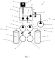
- Fig. 1 shows a dispenser 1 having an agent supply system 20, a carrier supply system 30, a mixing area 50 and a dispenser head 60.
- the agent supply system 20 and the carrier supply system 30 are independent from each other.
- the agent supply system 20 has an agent reservoir (oil reservoir) 22 for storing the agent 21 being perfume oil in the present embodiment.
- the oil reservoir 22 is connected via a first fluid path 25 with an input (upstream end) of a first micropump 23 (corresponding to an agent supply means in the present embodiment).
- the first micropump 23 is driven by a first drive unit 24 (e.g., an electric motor).
- An output (downstream end) of the first micropump 23 is connected via a second fluid path 26 with an input (upstream end) of a mixing chamber 50 (corresponding to a mixing area in the present embodiment).
- a first check valve (non-return valve) 27 is provided at an interface of the second fluid path 26 and the mixing chamber 50.
- the carrier supply system 30 has a carrier reservoir (water reservoir) 32 for storing the carrier 31 being water in the present embodiment.
- the water reservoir 32 is connected via a third fluid path 35 with an input (upstream end) of a second micropump 33 (corresponding to a carrier supply means in the present embodiment).
- the second micropump 33 is driven by a second drive unit 34 (e.g., an electric motor).
- An output (downstream end) of the second micropump 33 is connected via a fourth fluid path 36 with the input of the mixing chamber 50.
- a second check valve (non-return valve) 37 is provided at the interface of the fourth fluid path 36 and the mixing chamber 50.
- the preferred embodiment further comprises an optional fluid booster supply system 40.
- the fluid booster supply system 40 is a system for supplying pressurized air as a discharge booster to the mixing chamber 50.
- the fluid booster supply system 40 (air supply system) has an air pump 41 (corresponding to the booster supply means in the present embodiment).
- the air supply system 40 has a micro valve 42 for accurately controlling the airflow into the mixing chamber 50.
- a downstream end of the air pump 41 is connected with an upstream end of the micro valve 42 via a fifth fluid path 43.
- a downstream end of the micro valve 42 is connected via a sixth fluid path 44 with the input of the mixing chamber 50.
- a third check valve (non-return valve) 45 is provided at the interface of the sixth fluid path 44 and the mixing chamber 50.
- the air supply system 40 sucks the air by the air pump 41 either from an air reservoir (not shown) or from the outside of the dispenser 1.
- the three upstream ends of the second fluid path 26, the fourth fluid path 36, and the sixth fluid path 44 may be connected to an upstream end of a mixing junction interface 80, preferably by the first to third check valves 27, 37, and 45.
- the mixing junction interface 80 might be or comprise a valve, preferably including the first to third check valves 27, 37, and 45.
- a downstream end of the mixing junction interface 80 might be connected to the mixing chamber 50.
- the mixing junction interface 80 might be a part of the mixing area or mixing chamber 50.
- the oil 21 and the water 31 are mixed into striped patterns ( Fig. 5 ) to become the composition dose (perfume dose) 70 which is to be discharged to the outside (e.g., towards the user's skin).
- the mixing chamber 50 is connected directly or via a further fluid path to the dispenser head 60 downstream the mixing chamber 50.
- the perfume dose 70 flows through the dispenser head 60 and is discharged to the outside of the dispenser 1 via a spray nozzle 61 of the dispenser head 60.
- Fig. 2 shows another preferred embodiment having a mixing junction interface 80 including a 3/2-way valve 81.
- the valve 81 is connected on its upstream end (input ports) with the fourth fluid path 36 of the carrier supply system 30, and with the sixth fluid path 44 of the air supply system 40.
- the downstream end (output port) of the valve 81 is connected with the second fluid path 26 of the oil supply system 20.
- Fig. 3 is an partial enlarged view of the of the dispenser 1 of Fig. 2 showing the valve 81 in a first position, in which the fourth fluid path 36 is fluidly connected with the second fluid path 26 of the oil supply system 20 for mixing the oil 21 and the water 31 into the perfume dose 70.
- Fig. 4 is an partial enlarged view of the of the dispenser 1 of Fig. 2 showing the valve 81 in a second position, in which the sixth fluid path 44 is fluidly connected with the second fluid path 26 (or the upstream end of the mixing chamber 50 in which the perfume dose 70 is ready for discharge of the perfume dose 70 towards the outside of the dispenser 1 via the dispenser head 60).
- valve 81 The use of a switch valve corresponding to the valve 81 is particularly advantageous for the booster modes A and B (for the booster modes C and D, no such valve is needed). This kind of valve enables the release of the air. If the switch valve is integrated into the mixing junction interface 80, the switching valve can be switched between the first/second step (loading and mixing of the oil and the water) and the discharging step of the perfume 70.
- the advantages of using the switch valve 81 are that the pressurized air for the boost can be provided already during the mixing of the oil 21 and the water 31. This shortens the time that is required for the air boost. Further, the air is at the desired or set pressure level directly at the beginning of the discharging step of the perfume composition 70. Thus, the spraying of the perfume composition 70 can be improved. Additionally, the switch valve 81 prevents the oil 21 and the water 31 from entering the fluid booster supply system 40. Finally, the switch valve 81 allows optimizing the dead volume of the oil/water (fluids) and the air paths.
- the drawbacks of using a switch valve are that the system becomes more complex and expensive as well as larger than a system without the valve. Further, the valve increases the energy consumption of the dispenser.
- Fig. 5 schematically shows the discharging cycle of the dispenser 1.
- the oil 21 and the water 31 are sucked by the respective pumps 23, 33 in the first step (ingredients intake step, aspiration or input step).
- the doses of the oil 21 and the water 31 sucked into the pumps 23, 33 in the first step are then discharged to the mixing chamber 50 in the second step (ingredients dosing step, dispensing or output step).
- Fig. 5 shows the continuous flow of the oil 21 and the pulsed flow of the water 31.
- the doses of the continuous oil 21 and the pulsed water 31 are mixed in the mixing chamber 50 to form the striped pattern as depicted in Fig. 5 .
- the different hatchings show the layers of the oil 21 and water 31 in the perfume composition 70 which are stacked in the flowing direction (i.e., in the direction from the upstream end of the mixing chamber 50 to the downstream end of the mixing chamber 50).
- Fig. 5 the step of providing a fluid booster is shown. Air is sucked by the air pump 41 and is pressurized by the air pump 41 (as indicated by the rising pressure in the depicted diagram). The pressurized air is then released towards the mixing chamber 50 to start the fourth step (the discharging or spraying step of the perfume dose 70).
- Fig. 6 is a time diagram showing the discharging cycle of the dispenser 1.
- the user action is shown.
- the user merely has to perform the step of starting the dispensing process (the discharging cycle), for example, by pushing a button on the dispenser 1 or on another device such as a smartphone or a tablet.
- the operation of the oil micropump 23 is shown, which is performed at 1 to 5 Hz rotational speed of the pump.
- the operation of the oil micropump 23 including the dispensing and the aspiration steps of the oil starts after the user has started the dispensing process and starts simultaneously with the aspiration of the water 31.
- the oil micropump 23 first dispenses oil that has being aspirated in a preceding discharging cycle and has been accommodated (stored) in a pump chamber of the oil micropump 23.
- the duration of the processes shown in Fig. 6 is in the range of 60 to 400 milliseconds for the dosing (aspiration and dispensing) and the mixing steps (or 260 to 1400 milliseconds if an extended dose of the oil is used which is twice as large as a single dose of the oil).
- the duration is in a range of 500 microseconds to 1.5 seconds.
- Fig. 7 shows the result of one discharging cycle of the dispenser 1.
- the perfume dose has been sprayed on a glass plate.
- the photo has been made less than 15 seconds after the end of the discharging step of the perfume dose 70.
- the distance of the spray nozzle 61 to the glass plate was 15 centimeters.
- the mixing ratio of the oil and the carrier was 1/3.
- the volume of the perfume dose was 40 microliters.
- Fig. 7 shows three exemplary diameters [1] to [3] of the generated droplets, each being less than 0.3 millimeters. In the lower right part of Fig. 7 , a scale in millimeters is provided.
- Figs. 8 to 11 show four preferred types of a modular structure of the dispenser 1 according to the present invention.
- Fig. 8 shows type A1
- Fig. 9 shows type A2
- Fig. 10 shows type B1
- Fig. 11 shows type B2.
- the housing 10 and the first cartridge 90 are schematically shown by two dotted-and-dashed lines.
- the lower line defines the housing 10 of the dispenser 1
- the upper line defines the first cartridge 90 of the dispenser 1 in each of the Figs. 8 to 11 .
- the optional second cartridge 95 is shown by a dotted line in each of the Figs. 8 to 11 .
- the other depicted parts of the dispenser 1 correspond to the parts of the dispenser 1 as depicted in the preceding Figs. Therefore, the reference numbers for some of the depicted parts have been omitted for the sake of lucidity.
- the first and second drive units 24, 34 for the oil micropump 23 and the water micropump 33, the preferably provided air pump 41, the controller (not shown) of the dispenser 1, and the preferably provided micro valve 42 are provided in the housing 10.
- the housing 10 does not include components of the dispenser 1 that come into contact with the oil 21.
- the oil reservoir 22, the first micropump 23, the first check valve 27, the second check valve 37, the third check valve 45, the mixing junction interface 80 (preferably including the valve 81), the mixing chamber 50, and the dispenser head 60 are provided in the first cartridge 90.
- the water reservoir 32 and the second micropump 33 are also provided in the first cartridge 90.
- the water reservoir 32 and the second micropump 33 can be provided in the second cartridge 95 that is detachably mountable to the first cartridge 90. Accordingly, the first and second cartridges 90, 95 can form a cartridge unit that is detachably mountable to the housing 10.
- type A2 of the modular dispenser 1 differs from type A1 in that the second micropump 33 is accommodated by the housing 10.
- the modular dispenser 1 of the type A2 corresponds to that of the type A1.
- the type A2 is a particularly preferred modular structure of the dispenser 1 according to the present invention.
- the water reservoir 32 is included directly in the first cartridge 90 or alternatively in the second cartridge 95 that is mountable to the first cartridge 90.
- type B1 differs from type A2 in that the water reservoir 32 is accommodated directly in the housing 10 or in the optional second cartridge 95 that is removably mountable to the housing 10.
- the modular dispenser 1 of the type B 1 corresponds to that of the type A2.
- type B2 differs from type A1 in that the water reservoir 32 is accommodated directly in in the housing 10 or in the optional second cartridge 95 that is removably mountable to the housing 10.
- the modular dispenser 1 of the type B2 corresponds to that of the type A1.
- the water reservoir 32 is included in the housing 10 or in the second cartridge 95 that is mountable to the housing 10.
- the second cartridge 95 can be mountable to the first cartridge 90 and to the housing 10.
- the second cartridge 95 is first detachably mounted to the first cartridge 90 (or the other way round) and then both cartridges 90, 95 are mounted to the housing 10.
- only one of the two cartridges 90, 95 is directly mounted to the housing 10 while the other cartridge 95, 90 is mounted to the cartridge 90, 95 that is mounted to the housing 10.
- the two cartridges 90, 95 can be independently mounted to the housing 10. They can be mounted to each other while being mounted to the housing 10.
- a third cartridge (not shown) can be provided that is detachably mountable to the housing 10, to the first cartridge 90, and/or to the second cartridge 95.
- the third cartridge is configured to accommodate the oil reservoir 22.
- the third cartridge consists of (only) the oil reservoir 22 (i.e., is the carrier reservoir or includes only the carrier reservoir that is in a housing) and of a mechanical (and preferably an electronic) interface to the other parts of the dispenser, i.e., to the housing 10, to the first cartridge 90, and/or to the second cartridge 95.
Landscapes
- Chemical & Material Sciences (AREA)
- Chemical Kinetics & Catalysis (AREA)
- Engineering & Computer Science (AREA)
- Mechanical Engineering (AREA)
- General Engineering & Computer Science (AREA)
- Software Systems (AREA)
- Feeding, Discharge, Calcimining, Fusing, And Gas-Generation Devices (AREA)
Priority Applications (2)
| Application Number | Priority Date | Filing Date | Title |
|---|---|---|---|
| EP23175223.9A EP4467234A1 (fr) | 2023-05-25 | 2023-05-25 | Distributeur de fluide |
| PCT/EP2024/064436 WO2024240952A1 (fr) | 2023-05-25 | 2024-05-24 | Distributeur de fluide et procédé de distribution d'une dose de composition de fluide |
Applications Claiming Priority (1)
| Application Number | Priority Date | Filing Date | Title |
|---|---|---|---|
| EP23175223.9A EP4467234A1 (fr) | 2023-05-25 | 2023-05-25 | Distributeur de fluide |
Publications (1)
| Publication Number | Publication Date |
|---|---|
| EP4467234A1 true EP4467234A1 (fr) | 2024-11-27 |
Family
ID=86603724
Family Applications (1)
| Application Number | Title | Priority Date | Filing Date |
|---|---|---|---|
| EP23175223.9A Pending EP4467234A1 (fr) | 2023-05-25 | 2023-05-25 | Distributeur de fluide |
Country Status (2)
| Country | Link |
|---|---|
| EP (1) | EP4467234A1 (fr) |
| WO (1) | WO2024240952A1 (fr) |
Citations (6)
| Publication number | Priority date | Publication date | Assignee | Title |
|---|---|---|---|---|
| WO2001093997A1 (fr) * | 2000-06-02 | 2001-12-13 | The Regents Of The University Of California | Melange de fluide laminaire continu dans des systemes mecaniques microelectriques |
| WO2002064243A1 (fr) * | 2001-02-13 | 2002-08-22 | Qinetiq Limited | Dispositif a microcanal |
| US6764212B1 (en) * | 1998-11-10 | 2004-07-20 | Sipec Corporation | Chemical supply system |
| WO2005039674A1 (fr) | 2003-10-27 | 2005-05-06 | Ecole Polytechnique Federale De Lausanne (Epfl) | Micropompe pour l'administration d'un medicament liquide |
| WO2007074363A2 (fr) | 2005-12-28 | 2007-07-05 | Sensile Pat Ag | Micropompe |
| WO2019115276A1 (fr) | 2017-12-12 | 2019-06-20 | Sensile Medical Ag | Micropompe ayant un mécanisme de came pour un déplacement axial d'un rotor |
-
2023
- 2023-05-25 EP EP23175223.9A patent/EP4467234A1/fr active Pending
-
2024
- 2024-05-24 WO PCT/EP2024/064436 patent/WO2024240952A1/fr not_active Ceased
Patent Citations (6)
| Publication number | Priority date | Publication date | Assignee | Title |
|---|---|---|---|---|
| US6764212B1 (en) * | 1998-11-10 | 2004-07-20 | Sipec Corporation | Chemical supply system |
| WO2001093997A1 (fr) * | 2000-06-02 | 2001-12-13 | The Regents Of The University Of California | Melange de fluide laminaire continu dans des systemes mecaniques microelectriques |
| WO2002064243A1 (fr) * | 2001-02-13 | 2002-08-22 | Qinetiq Limited | Dispositif a microcanal |
| WO2005039674A1 (fr) | 2003-10-27 | 2005-05-06 | Ecole Polytechnique Federale De Lausanne (Epfl) | Micropompe pour l'administration d'un medicament liquide |
| WO2007074363A2 (fr) | 2005-12-28 | 2007-07-05 | Sensile Pat Ag | Micropompe |
| WO2019115276A1 (fr) | 2017-12-12 | 2019-06-20 | Sensile Medical Ag | Micropompe ayant un mécanisme de came pour un déplacement axial d'un rotor |
Also Published As
| Publication number | Publication date |
|---|---|
| WO2024240952A1 (fr) | 2024-11-28 |
Similar Documents
| Publication | Publication Date | Title |
|---|---|---|
| US7833192B2 (en) | Device for dispensing substances | |
| EP3157587B1 (fr) | Système de distribution microfluidique pour libération de compositions fluides | |
| CN104053357B (zh) | 分配液体混合物的系统和方法 | |
| JP5592113B2 (ja) | 液体をパルス吐出するための装置及び方法 | |
| CN105142797B (zh) | 零件数量减少的水平泵、再填充单元以及分配器 | |
| KR950704054A (ko) | 분배 정치(dispensing apparatus) | |
| US8967493B2 (en) | Atomizing device | |
| SI25886A (sl) | Naprava za doziranje parfuma | |
| CA2677011A1 (fr) | Pochette souple de distribution de dosage avec une buse de pulverisation | |
| JP7546577B2 (ja) | 化粧品を分配するための流体ディスペンサ | |
| EP1559436B1 (fr) | Système pour l'atomisation de liquides | |
| JPH02253871A (ja) | 植物保護性組成物を施用するための装置 | |
| EP4467234A1 (fr) | Distributeur de fluide | |
| EP4467233A1 (fr) | Distributeur de fluide | |
| EP4467244A1 (fr) | Distributeur de fluide | |
| US20190225479A1 (en) | System for preparing a personalized composition using pressure | |
| AU2013280697B2 (en) | Grit and foam dispenser | |
| US20040084555A1 (en) | Device for mixing and delivering pharmaceutical compositions | |
| KR20230169947A (ko) | 모터 구동 공기 펌프, 분배 장치 및 생성물 컨테이너를 포함하는 생성물 분배 시스템 | |
| RU2815909C1 (ru) | Дозирующее устройство для парфюма | |
| EP4686489A1 (fr) | Inhalateur de brouillard mou | |
| US20260108905A1 (en) | Liquid dispenser | |
| HK1078499A (en) | Spray system for atomising liquids |
Legal Events
| Date | Code | Title | Description |
|---|---|---|---|
| PUAI | Public reference made under article 153(3) epc to a published international application that has entered the european phase |
Free format text: ORIGINAL CODE: 0009012 |
|
| STAA | Information on the status of an ep patent application or granted ep patent |
Free format text: STATUS: REQUEST FOR EXAMINATION WAS MADE |
|
| 17P | Request for examination filed |
Effective date: 20230525 |
|
| AK | Designated contracting states |
Kind code of ref document: A1 Designated state(s): AL AT BE BG CH CY CZ DE DK EE ES FI FR GB GR HR HU IE IS IT LI LT LU LV MC ME MK MT NL NO PL PT RO RS SE SI SK SM TR |