EP4467243A2 - Embout de buse remplaçable pour un appareil dentaire à jet de poudre - Google Patents
Embout de buse remplaçable pour un appareil dentaire à jet de poudre Download PDFInfo
- Publication number
- EP4467243A2 EP4467243A2 EP24205566.3A EP24205566A EP4467243A2 EP 4467243 A2 EP4467243 A2 EP 4467243A2 EP 24205566 A EP24205566 A EP 24205566A EP 4467243 A2 EP4467243 A2 EP 4467243A2
- Authority
- EP
- European Patent Office
- Prior art keywords
- nozzle tip
- longitudinal section
- powder
- tip according
- longitudinal
- Prior art date
- Legal status (The legal status is an assumption and is not a legal conclusion. Google has not performed a legal analysis and makes no representation as to the accuracy of the status listed.)
- Pending
Links
Images



Classifications
-
- A—HUMAN NECESSITIES
- A61—MEDICAL OR VETERINARY SCIENCE; HYGIENE
- A61C—DENTISTRY; APPARATUS OR METHODS FOR ORAL OR DENTAL HYGIENE
- A61C17/00—Devices for cleaning, polishing, rinsing or drying teeth, teeth cavities or prostheses; Saliva removers; Dental appliances for receiving spittle
- A61C17/02—Rinsing or air-blowing devices, e.g. using fluid jets or comprising liquid medication
- A61C17/0202—Hand-pieces
-
- A—HUMAN NECESSITIES
- A61—MEDICAL OR VETERINARY SCIENCE; HYGIENE
- A61C—DENTISTRY; APPARATUS OR METHODS FOR ORAL OR DENTAL HYGIENE
- A61C3/00—Dental tools or instruments
- A61C3/02—Tooth drilling or cutting instruments; Instruments acting like a sandblast machine
- A61C3/025—Instruments acting like a sandblast machine, e.g. for cleaning, polishing or cutting teeth
-
- B—PERFORMING OPERATIONS; TRANSPORTING
- B05—SPRAYING OR ATOMISING IN GENERAL; APPLYING FLUENT MATERIALS TO SURFACES, IN GENERAL
- B05B—SPRAYING APPARATUS; ATOMISING APPARATUS; NOZZLES
- B05B1/00—Nozzles, spray heads or other outlets, with or without auxiliary devices such as valves, heating means
- B05B1/26—Nozzles, spray heads or other outlets, with or without auxiliary devices such as valves, heating means with means for mechanically breaking-up or deflecting the jet after discharge, e.g. with fixed deflectors; Breaking-up the discharged liquid or other fluent material by impinging jets
- B05B1/262—Nozzles, spray heads or other outlets, with or without auxiliary devices such as valves, heating means with means for mechanically breaking-up or deflecting the jet after discharge, e.g. with fixed deflectors; Breaking-up the discharged liquid or other fluent material by impinging jets with fixed deflectors
- B05B1/267—Nozzles, spray heads or other outlets, with or without auxiliary devices such as valves, heating means with means for mechanically breaking-up or deflecting the jet after discharge, e.g. with fixed deflectors; Breaking-up the discharged liquid or other fluent material by impinging jets with fixed deflectors the liquid or other fluent material being deflected in determined directions
-
- B—PERFORMING OPERATIONS; TRANSPORTING
- B05—SPRAYING OR ATOMISING IN GENERAL; APPLYING FLUENT MATERIALS TO SURFACES, IN GENERAL
- B05B—SPRAYING APPARATUS; ATOMISING APPARATUS; NOZZLES
- B05B7/00—Spraying apparatus for discharge of liquids or other fluent materials from two or more sources, e.g. of liquid and air, of powder and gas
- B05B7/14—Spraying apparatus for discharge of liquids or other fluent materials from two or more sources, e.g. of liquid and air, of powder and gas designed for spraying particulate materials
- B05B7/1481—Spray pistols or apparatus for discharging particulate material
- B05B7/149—Spray pistols or apparatus for discharging particulate material with separate inlets for a particulate material and a liquid to be sprayed
- B05B7/1495—Spray pistols or apparatus for discharging particulate material with separate inlets for a particulate material and a liquid to be sprayed and with separate outlets for the particulate material and the liquid
-
- B—PERFORMING OPERATIONS; TRANSPORTING
- B24—GRINDING; POLISHING
- B24C—ABRASIVE OR RELATED BLASTING WITH PARTICULATE MATERIAL
- B24C5/00—Devices or accessories for generating abrasive blasts
- B24C5/02—Blast guns, e.g. for generating high velocity abrasive fluid jets for cutting materials
- B24C5/04—Nozzles therefor
Definitions
- the invention relates to a replaceable nozzle tip for a dental powder jet device.
- Powder jet devices are used in the dental field for supra- and subgingival application in prophylactic treatments.
- a mixture of powder and air is directed onto the tooth to remove any deposits present there.
- Water is also added to remove the powder and deposits, or the water surrounds the powder-air jet and ensures that no excessive dust is generated.
- the known powder jet devices usually have replaceable nozzle tips that guide the powder-air mixture and water to the tooth and thus come into contact with it.
- nozzle tips are dimensioned so that they can also be used within a gum pocket.
- a nozzle piece for a dental powder jet device that also enables subgingival treatment.
- the nozzle piece has several nozzle openings that are formed in the surface of a front section of a tube. The powder-air mixture escapes through these several openings.
- a channel is provided concentrically to the tube for guiding water.
- this document proposes making the tube oval so that it can be better inserted into a periodontal pocket.
- a replaceable nozzle tip for a dental powder jet device is also known.
- the nozzle tip has a single outlet opening for the powder-air mixture and another opening at the long end for water. Due to the two channels for water and the powder-air mixture running inside the nozzle tip, the nozzle has a non-circular oval shape, which also leads to the disadvantages mentioned above.
- one object of the present invention is to provide a replaceable nozzle tip for a dental powder jet device that overcomes the aforementioned disadvantages.
- the replaceable nozzle tip is intended in particular to reduce the risk of emphysema formation and to achieve high flexibility and a large jet area without compromising stability.
- the replaceable nozzle tip has an elongated body which is divided into a first and a second longitudinal section, the first longitudinal section having a connection interface for detachable attachment to the powder jet device and the second longitudinal section having a circular cross-section with an inner channel for a powder-air mixture and an outer lateral surface.
- At least one water guide element extending in the longitudinal direction is assigned to the lateral surface of the second longitudinal section.
- a single outlet opening for the powder-air mixture is provided on the lateral surface of the second longitudinal section, into which the inner channel opens, and the first longitudinal section has at least one opening for water in its area facing the second longitudinal section, the at least one opening opening into the at least one water guide element.
- the nozzle tip according to the invention has only one inner channel, which opens into the only outlet opening for the powder-air mixture on the jacket surface.
- a separate channel for the water is not provided, at least in the second longitudinal section. Instead, the water runs out of the openings to the jacket surface and along it, with the water guide element in the simplest case being the jacket surface itself.
- the outlet opening has an opening area that extends over at least a quarter of the circumference of the longitudinal section.
- the outlet opening is preferably delimited by two first surfaces that extend at least partially radially and two second surfaces that extend obliquely or parallel to the longitudinal axis, the two first surfaces being spaced apart in the longitudinal direction and the two second surfaces being spaced apart in the circumferential direction.
- This design of the outlet opening enables a fanned-out jet of the powder-air mixture that is not directed directly downwards. So, even though there is only one outlet opening, a large area of the tooth can be reached by the powder-air mixture.
- the first surface facing away from the first longitudinal section has a plurality of surface areas that are offset in the longitudinal direction.
- three surface areas that follow one another in the circumferential direction are provided, with the middle surface area lying in a radial plane and, viewed in the longitudinal direction, being closer to the first longitudinal section than the two other outer surface areas.
- the two outer surface areas are mirror-symmetrical to a longitudinal plane and are each rounded.
- a deflection surface is provided in the region of the inner channel which opens into the outlet opening, which is arranged obliquely to the longitudinal axis in such a way that the powder-air mixture is guided outwards.
- the deflection surface preferably merges into the middle surface region of the first surface.
- This special geometry of the outlet opening further improves the powder-air mixture jet.
- the first longitudinal section has, at the transition to the second longitudinal section, an annular surface preferably lying in a radial plane, in which the at least one opening for water is provided.
- the at least one water guide element is designed as a channel-shaped recess in the lateral surface of the second longitudinal section.
- at least one of the water guide elements extends into the immediate vicinity of the outlet opening.
- This design has the advantage that the water in the channel-shaped recess can be better guided downwards in the longitudinal direction, ie in the direction of the downstream end of the nozzle tip.
- water guide elements are provided, which correspond to several, preferably six, openings for water.
- the inner channel has, at least in sections, a rectangular, preferably square cross-section.
- connection interface has at least one holding element which is designed to cooperate with corresponding holding elements, preferably locking lugs, on the powder blasting device, so that the nozzle tip is prevented from falling off the powder blasting device.
- the retaining element takes effect precisely when the nozzle tip detaches from the powder jet device.
- the retaining element prevents the nozzle tip from falling completely off the powder jet device, which could lead to unpleasant consequences when used in a patient's mouth.
- the holding element is designed as a guarantee ring which has a predetermined breaking point, so that when the nozzle tip is released from the powder jet device, the guarantee ring breaks open at the predetermined breaking point.
- the nozzle tip can only be completely removed from the powder blasting device if the retaining element is damaged.
- the user can completely remove the nozzle tip without exerting much force.
- the guarantee ring now allows the user to immediately see whether the nozzle tip has already been used before.
- the guarantee ring is arranged at one end of the first longitudinal section and is connected to the following section of the first longitudinal section via a web running in the longitudinal direction. Further preferably, several support elements are provided on the following section, which are designed to support the guarantee ring when it is pushed on over the locking lugs.
- the guarantee ring is carried along by the support elements, although the guarantee ring is connected to the following section at a web, i.e. only at one section when viewed in the circumferential direction.
- an orientation element is provided on the first longitudinal section, which is provided in a predetermined spatial relationship to the outlet opening.
- This measure has the advantage that the user can easily determine where the outlet opening is located via this orientation element, which is particularly necessary when the outlet opening is not close enough or is difficult for the user to see.
- a scale in particular a WHO probe scale, is provided on the outside of the second longitudinal section for determining the depth of a periodontal pocket.
- the advantage of this measure is that the marking provides the user with good orientation when working.
- the use of a so-called WHO scale is also advantageous because this scale is already used in other dental instruments, such as periodontal probes. The user therefore does not have to adjust to a new scale.
- connection interface is designed as a so-called bayonet lock.
- the nozzle tip is first inserted into an opening in the connection area of the powder jet device and then rotated. By rotating the nozzle tip relative to the powder jet device, it is pulled into the connection area and thus sealed to the powder jet device. To release the nozzle tip, all that is required is a rotation in the opposite direction.
- This solution has the advantage of providing a secure connection that the user can feel. By reaching an end stop when screwing in the nozzle tip, the user can see that the nozzle tip is securely connected.
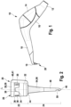
- a powder jet device is shown schematically and identified with the reference number 10.
- Such a powder jet device 10 is used in the dental field for cleaning teeth. Cleaning is carried out with a preferably fine-grained powder that is mixed with air and blasted onto the tooth to be cleaned as a powder-air mixture. Water is used to remove the powder and reduce dust formation, which is also brought to the tooth to be cleaned via the powder jet device 10.
- the powder blasting device 10 is connected to a media hose of a treatment chair, whereby the powder blasting device 10 has a connection coupling 12 for this purpose.
- This connection coupling 12 enables the connection of a media hose that supplies the powder blasting device 10 with air, water and, if necessary, electrical energy.
- the powder blasting device 10 also has a container 14 that holds the powder required for cleaning.
- the powder from this container 14 is mixed with the supplied air, e.g. compressed air, so that a powder-air mixture is created, which is guided via an internal channel in the powder blasting device 10 to a nozzle tip 20.
- This powder-air mixture exits this nozzle tip 20, whereby the special design of this nozzle tip 20 will be discussed in detail later.
- the powder blasting device 10 is designed as a hand-held device and has, as in Figure 1 can be seen, an L-shaped design, with a first section 16, in which the connection coupling 12 and the container 14 are located, and a second section 18, at the end 19 of which the nozzle tip 20 can be attached.
- the powder jet device 10 shown can be used for both supragingival treatment of a tooth, i.e. treatment above the gum line, and subgingival treatment of a tooth, i.e. below the gum line.
- ends 19 can be used for supragingival treatment (i.e. the powder jet device is used without using a nozzle tip) and nozzle tips 20 for supgingival treatment.
- a nozzle tip 20 designed for subgingival treatment is described below. In other words, the dimensions of the nozzle tip 20 are designed so that it can be immersed in gum pockets.
- the nozzle tip 20 itself is designed as a disposable item, so that the nozzle tip 20 is thrown away after its first use.
- FIG. 2 Such a nozzle tip 20 is now shown schematically in a side view.
- the nozzle tip 20 has an elongated shape with a longitudinal axis L and is divided into a first longitudinal section 22 and an adjoining second longitudinal section 24.
- a connection interface 26 is provided in the first longitudinal section 22, which interacts with a correspondingly designed interface at the end 19 of the second section 18 of the powder jet device 10.
- the connection interface 26 ensures in particular that both the powder-air mixture and water can reach the nozzle tip without causing a leak.
- the connection interface 26 comprises a ring 28 which acts as a guarantee ring 29, which will be explained below.
- support elements 38 are provided, which extend in the direction of the underside 36 of the ring 28 and end at a small distance from the underside 36.
- the support elements 38 are distributed along the preferably circular edge 34, preferably evenly.
- the support elements 38 have the function of supporting the ring 28 should it be bent in the direction of the upper edge 34.
- a flag-shaped element 40 extends over the entire length of the first longitudinal section 22 and runs radially outwards.
- This flag-shaped element 40 serves as an optical orientation or alignment element 41 in order to be able to make and check the connection to the powder blasting device 10 in a specific position.
- the user should be able to easily determine the orientation of the outlet opening using the alignment element 41.
- the alignment element 41 must therefore be placed in a defined spatial relationship to the outlet opening 50.
- the powder-air mixture passes from the connection interface 26 to the outlet opening 50 via an inner channel 82 (cf. Fig. 5a ), which preferably extends concentrically through the second longitudinal section 24 and opens into the outlet opening 50.
- water is also supplied via the nozzle tip 20 during the treatment in order to rinse the powder out of the gum pocket, for example, and to avoid dust formation.
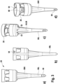
- several water openings 52 are provided in the ring surface 44, as for example in Figure 3c can be seen.
- six such water openings 52 can be provided in the ring surface 44 at equal distances from one another.
- the water openings 52 are provided so close to the outer surface 48 of the second longitudinal section 24 that the escaping water can run down the outer surface towards the lower end 46, whereby the so-called Coanda effect is utilized.
- the outer surface 48 thus also serves as a water guide element.
- water guidance elements 54 are provided on the lateral surface 48, which are designed, for example, as channel-shaped elements 56. These channel-shaped elements 56 extend longitudinally downwards, ie in the direction of the lower end 46, whereby the length of the individual channel-shaped elements 56 can be different. As can be seen from the Figures 3a to d Long channel-shaped elements 56L and short channel-shaped elements 56K are provided alternately in the circumferential direction of the lateral surface 48. One of the channel-shaped elements 56L ends just above the upper end of the outlet opening 50, as shown in Figure 3a is clearly visible.
- the second longitudinal section 24 Since the water is guided via the lateral surface 48, the second longitudinal section 24 only needs a single internal channel for the powder-air mixture, so that the cross-section of this longitudinal section 24 can be correspondingly small (compared to a solution with two internal channels). Correspondingly small dimensions of the second longitudinal section 24 make it easier to immerse it in a gum pocket and, due to the circular cross-section, also lead to flexibility that is the same in all directions (compared to rectangular or oval cross-sections, which do not offer uniform flexibility in all directions).
- the channel-shaped elements 56 themselves begin in the immediate area of the annular surface 44 and are aligned with the water openings 52. In other words, this means that the longitudinal axis of a channel-shaped element 56 and the center of the preferably circular water opening 52 lie in the same longitudinal plane.
- connection interface 26 has a preferably circular opening 60 coaxial with the longitudinal axis L, which represents the upper end of the inner channel 82.
- the opening cross-section of the opening 60 is larger than the opening cross-section of the outlet opening 50, so that a nozzle effect, ie an acceleration of the powder-air mixture downwards towards the outlet opening 50 is achieved by the decreasing flow cross-section.
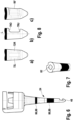
- the inner channel 82 as shown in Figure 7 shown may have a rectangular or square shape, at least in sections.
- the ring 28 forms the upper end of the nozzle tip 20.
- This ring 28 has a notch 64, as shown in the Figures 3b and d can be easily recognized.
- This notch 64 in the ring 28 serves as a weakening of the material and thus as a predetermined breaking point at which the ring 28 can tear open. The possibility of tearing open serves to provide a guarantee function for the ring 28.
- the ring should tear open at this predetermined breaking point so that the user can easily see whether the nozzle tip 20 is unused or not.
- annular space above the annular surface 44, which is connected to the water openings 52.
- This annular space is supplied with water via a channel that opens into an opening in the connection interface 26.
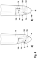
- nozzle tip 20 One of the special features of the nozzle tip 20 is the design of the outlet opening 50. This design is described below with reference to the Figure 4a, b explained in more detail.
- the outlet opening 50 is provided as a cutout in the lateral surface 48, with an extension in the circumferential direction of almost 180°, so that an opening angle of preferably about 130° results, and in the longitudinal direction of preferably about 0.9 mm to 1.3 mm.
- the outlet opening 50 in the lateral surface 48 is delimited by several surfaces, namely an upper and a lower first surface 700, 70U and a left and a right second surface 72L, 72R.
- the terms "lower” and "upper” refer to the relationship to the lower end 46, ie the lower surface is closer to the lower end 46 than the upper surface.
- the two second surfaces 72L, 72R preferably lie in a plane that extends obliquely to the longitudinal axis L.
- the inclination is selected such that the upper region of the second surfaces is at a greater distance from the longitudinal axis than the lower region of the second surfaces.
- the upper first surface extends substantially perpendicular to the longitudinal axis L.
- the lower first surface is divided into three surface areas 74, namely a left surface area 74L, a middle surface area 74M and a right surface area 74R.
- the middle surface area 74M is located above the two adjacent surface areas 74L, 74R, ie the middle surface area 74M has a greater longitudinal distance from the lower end 46 than the other two surface areas 74L, 74R.
- the middle surface area 74M extends at least in sections perpendicular to the longitudinal axis L.
- the width B of the middle surface area 74M corresponds approximately to the width of the inner channel 82.
- the extension of the outlet opening in the longitudinal direction is preferably 0.9 mm in the area of the middle surface area 74M and preferably 1.3 mm in the area of the other two surface areas 74L, 74R.
- a deflection surface 76 which runs obliquely to the longitudinal axis and is preferably at an angle of approximately 45° to the longitudinal axis and thus also to the direction of flow of the powder-air mixture.
- the deflection surface 76 merges in its lower area into the middle area 74M. This also means that the width of this deflection surface 76 corresponds approximately to the width of the middle area 74M. This deflection surface 76 serves to deflect the powder-air mixture outwards approximately radially to the longitudinal axis.
- transitions between the surfaces or surface areas are rounded, so that there are softer transitions, which is advantageous from a fluid dynamics point of view.
- the geometry of the outlet opening 50 enables a jet of powder-air mixture to be strongly fanned out to both sides (left and right), while at the same time preventing the jet effect from being directed downwards, ie towards the lower end 46 becomes too large.
- the central surface area 74M, which forms a kind of rib, and the two side surface areas 74L and 74R, which act as ramps, enable the very broadly fanned out jet of a powder-air mixture, so that a relatively large area of the tooth to be treated can be reached.
- FIG. 5a b
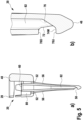
- the nozzle tip 20 is shown in a longitudinal section.
- this longitudinal section in Figure 5a On the one hand, the already mentioned annular space can be seen in the first longitudinal section, which is marked with the reference number 80.
- the inner channel is shown and marked with the reference number 82, which extends from the opening 60 to the outlet opening 50.
- the upper first surface 70O and the middle surface area 74M of the lower first surface 70U extend essentially parallel to one another.
- the deflection surface 76 merges into the middle surface area 74M.
- a nozzle tip 20 which corresponds to the nozzle tip 20 described above, but additionally has a marking 86 in the area of the second longitudinal section 24.
- the marking 86 has one or more marking elements 88 in the form of optically recognizable stripes running in the circumferential direction, which have a defined distance from the lower end 46.
- the marking 86 and in particular the marking elements 88 are intended to visually indicate to the user how deeply the nozzle tip has already been immersed in a gum pocket.
- the marking 86 is preferably selected as is known from so-called periodontal meters (WHO probe).
- FIG 8 An alternative design of an outlet opening is shown and is identified by the reference numeral 50'.
- This outlet opening 50' differs from the previously described outlet opening 50 in that the lower first surface 70U has only one surface area instead of the previously described three surface areas.
- the Figure 8 The design shown therefore does not have a rib-like central surface area.
- this alternative design also has an opening area in the horizontal direction of almost 180 degrees.
- the deflection surface 76 here extends radially to the longitudinal axis L.
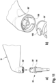
- connection area 90 at the end of the second section 18 of the powder jet device 10 has holding elements, for example locking lugs 92, with preferably four locking lugs 92 evenly distributed in the circumferential direction.
- the locking lugs 92 each have a surface that runs obliquely to the circumferential surface and a surface that runs perpendicular to the circumferential surface.
- the vertical surface, ie the locking surface is in the upper area, ie it is further away from the end of the second section 18 than the respective oblique surface.
- the ring 28 slides over the inclined surfaces of the locking lugs 92, whereby the ring expands slightly, but without tearing at the predetermined breaking point.
- the support elements 38 are provided, which support the ring 28 against excessive downward deflection.
- the ring 28 now has the function of preventing the nozzle tip 20 from falling off during use. Even if the clamping provided by the sealing surfaces between the connection area 90 and the connection interface 26 were to be lost, the ring 28 cannot run over the locking lugs 92 without additional manual effort. Instead, the nozzle tip 20 then remains hanging on the connection area 90 via the ring 28.
- the user must apply force to tear open the ring 28 at the predetermined breaking point 64.
- This torn ring which then functions as a guarantee ring 29, shows that the nozzle tip has already been used.
- connection interface 26 has a cylindrical section 94 which divides the interior of the cylindrical area 32 into an outer annular space 96 and an inner space 98.
- the connection area 90 is now designed in such a way that it can dip into the annular space 96 and the inner space 98 and then cooperates there with the corresponding lateral surfaces of the cylindrical area 32 to form a seal.
- a seal 100 is provided, and between the outer surface of the connection area 90 and the inner surface of the cylindrical area 32, a seal 102 is also provided.
- the powder-air mixture flows via a channel in the powder jet device 10 into the inner space 98, while water reaches the annular space 96 via a second channel in the powder jet device 10. Due to the seals provided, water can only escape via the water openings 52 provided, and thanks to the seal 100, the powder-air mixture does not reach the area of the annular space 96. As already briefly indicated above, the nozzle tip 20 is held on the connection area 90 of the powder jet device 10 via the corresponding clamping and the frictional connection by the seals 100,102.
- a nozzle tip 20 is shown schematically, which has an alternative connection interface 26'.
- the connection area 90' of the powder jet device 10 is also adapted accordingly.
- the connection interface 26' no longer has a ring 28, which is intended to prevent the nozzle tip from falling off. Instead, a so-called bayonet lock is provided, whereby, for example, two cams 106 on the connection interface 26' interact with a bayonet curve 108, which is formed on the inside of the connection area 90'.
- the connection interface 26' is first inserted into the opening of the connection area 90', whereby the cams 106 are aligned with the bayonet curve 108.
- gripping elements 110 are provided in the second longitudinal section 24, which extend radially outward and have a certain length in the longitudinal direction.
- two gripping elements 110 are provided on opposite sides below the annular surface 44.
- the previously explained nozzle tips 20 are made of a plastic. Since the second longitudinal section 24 is very slim and essentially circular, a material can generally be used that has a relatively good service life in use, but still has flexibility for a pleasant Work has. In particular in the lower area of the second longitudinal section 24 and preferably also due to the rectangular or square cross-section of the inner channel, a sufficient wall thickness remains available, which offers flexibility but prevents the tip from bending.
- the nozzle tip 20 described can be manufactured cost-effectively, so that a cost-effective sterile single-use product can be provided.
- Paragraph 1 Replaceable nozzle tip (20) for a dental powder jet device (10), with an elongated body which is divided into a first (22) and a second longitudinal section (24), the first longitudinal section (22) having a connection interface (26) for detachable attachment to the powder jet device and the second longitudinal section (24) having a circular cross-section with an inner channel (82) for a powder-air mixture and an outer lateral surface (48), characterized in that at least one water guide element (54) extending in the longitudinal direction is provided on the lateral surface (48) of the second longitudinal section (24), a single outlet opening (50) for the powder-air mixture is provided on the lateral surface (48) of the second longitudinal section (24), into which the inner channel (82) opens, and the first longitudinal section (22) has at least one opening (52) for water in its area facing the second longitudinal section. wherein the at least one opening (52) opens into the at least one water guide element (54).
- Nozzle tip according to paragraph 1 characterized in that the outlet opening (50) has an opening area which extends over at least a quarter, preferably half, of the circumference of the longitudinal section.
- Nozzle tip according to paragraph 1 or 2 characterized in that the outlet opening is delimited by two at least partially radially extending first surfaces (70) and two second surfaces (72) extending obliquely or parallel to the longitudinal axis, the two first surfaces (70) being spaced apart in the longitudinal direction and the two second surfaces (72) being spaced apart in the circumferential direction.
- Nozzle tip according to paragraph 3 characterized in that the first surface (70U) facing away from the first longitudinal section has a plurality of surface areas (74) which are arranged offset in the longitudinal direction.
- Nozzle tip according to paragraph 4 characterized in that three surface areas (74L, 74M, 74R) are provided which follow one another in the circumferential direction, the middle surface area (74M) lying in a radial plane and, viewed in the longitudinal direction, being closer to the first longitudinal section than the other two outer surface areas (74L, 74R).
- Nozzle tip according to paragraph 4 or 5 characterized in that the two outer surface areas (74L, 74R) are mirror-symmetrical to a longitudinal plane and are each rounded.
- Nozzle tip according to one of the preceding paragraphs, characterized in that in the region of the inner channel (82) which opens into the outlet opening (50), a deflection surface (76) is provided which is arranged obliquely to the longitudinal axis (L) in such a way that the powder-air mixture is guided to the outside.
- Paragraph 8 Nozzle tip according to paragraphs 5 and 7, characterized in that the deflection surface (76) merges into the central surface region (74M) of the first surface (72U).
- Nozzle tip according to one of the preceding paragraphs, characterized in that the first longitudinal section at the transition to the second longitudinal section has an annular surface (44) preferably lying in a radial plane, in which the at least one opening (52) for water is provided.
- Nozzle tip according to one of the preceding paragraphs, characterized in that the outer surface (48) serves as a water guide element (54).
- Nozzle tip according to one of the preceding paragraphs characterized in that the at least one water guide element (54) is designed as a channel-shaped recess (56) in the lateral surface (48) of the second longitudinal section (24).
- Nozzle tip according to paragraph 11 characterized in that at least one of the water guide elements (56) extends into the immediate vicinity of the outlet opening.
- Nozzle tip according to one of the preceding paragraphs, characterized in that several, preferably six water guide elements (56) and several, preferably six openings (52) for water are provided.
- Nozzle tip according to one of the preceding paragraphs characterized in that the inner channel (82) has a rectangular cross-section at least in sections.
- connection interface (26) has at least one holding element (28) which is designed to cooperate with corresponding holding elements (92), preferably locking lugs, on the powder blasting device, so that the nozzle tip is prevented from falling off the powder blasting device.
- Nozzle tip according to paragraph 15 characterized in that the holding element (28) is designed as a guarantee ring (29) which has a predetermined breaking point (64) so that when the nozzle tip is released from the powder blasting device, the guarantee ring breaks open at the predetermined breaking point.
- Nozzle tip according to paragraph 16 characterized in that the guarantee ring (29) is arranged at one end of the first longitudinal section and is connected to the following section of the first longitudinal section via a web (30) running in the longitudinal direction.
- Nozzle tip according to paragraph 17 characterized in that several support elements (38) are provided on the following section, which are designed to support the guarantee ring (29) when pushed over the locking lugs (92).
- Nozzle tip according to one of paragraphs 1 to 14, characterized in that the connection interface (26') is designed as a bayonet closure (106).
- Paragraph 20 Nozzle tip according to one of the preceding paragraphs, characterized in that an orientation element (40, 41) is provided on the first longitudinal section, which is provided in a predetermined spatial relationship to the outlet opening (50).
Landscapes
- Health & Medical Sciences (AREA)
- Dentistry (AREA)
- Epidemiology (AREA)
- Life Sciences & Earth Sciences (AREA)
- Animal Behavior & Ethology (AREA)
- General Health & Medical Sciences (AREA)
- Public Health (AREA)
- Veterinary Medicine (AREA)
- Oral & Maxillofacial Surgery (AREA)
- Dental Tools And Instruments Or Auxiliary Dental Instruments (AREA)
Applications Claiming Priority (2)
| Application Number | Priority Date | Filing Date | Title |
|---|---|---|---|
| DE102018126926.9A DE102018126926A1 (de) | 2018-10-29 | 2018-10-29 | Auswechselbare Düsenspitze für ein dentales Pulverstrahlgerät |
| EP19205136.5A EP3646811B1 (fr) | 2018-10-29 | 2019-10-24 | Embout de buse remplaçable pour un appareil à jet de poudres dentaire |
Related Parent Applications (2)
| Application Number | Title | Priority Date | Filing Date |
|---|---|---|---|
| EP19205136.5A Division-Into EP3646811B1 (fr) | 2018-10-29 | 2019-10-24 | Embout de buse remplaçable pour un appareil à jet de poudres dentaire |
| EP19205136.5A Division EP3646811B1 (fr) | 2018-10-29 | 2019-10-24 | Embout de buse remplaçable pour un appareil à jet de poudres dentaire |
Publications (2)
| Publication Number | Publication Date |
|---|---|
| EP4467243A2 true EP4467243A2 (fr) | 2024-11-27 |
| EP4467243A3 EP4467243A3 (fr) | 2025-02-19 |
Family
ID=68342824
Family Applications (2)
| Application Number | Title | Priority Date | Filing Date |
|---|---|---|---|
| EP19205136.5A Active EP3646811B1 (fr) | 2018-10-29 | 2019-10-24 | Embout de buse remplaçable pour un appareil à jet de poudres dentaire |
| EP24205566.3A Pending EP4467243A3 (fr) | 2018-10-29 | 2019-10-24 | Embout de buse remplaçable pour un appareil dentaire à jet de poudre |
Family Applications Before (1)
| Application Number | Title | Priority Date | Filing Date |
|---|---|---|---|
| EP19205136.5A Active EP3646811B1 (fr) | 2018-10-29 | 2019-10-24 | Embout de buse remplaçable pour un appareil à jet de poudres dentaire |
Country Status (2)
| Country | Link |
|---|---|
| EP (2) | EP3646811B1 (fr) |
| DE (1) | DE102018126926A1 (fr) |
Families Citing this family (1)
| Publication number | Priority date | Publication date | Assignee | Title |
|---|---|---|---|---|
| CN211325726U (zh) * | 2019-11-13 | 2020-08-25 | 桂林市啄木鸟医疗器械有限公司 | 一种可旋转牙科喷砂机龈下喷头喷嘴 |
Citations (2)
| Publication number | Priority date | Publication date | Assignee | Title |
|---|---|---|---|---|
| DE10331583B3 (de) | 2003-07-11 | 2004-07-15 | Ferton Holding S.A. | Düsenstück für ein dentales Pulverstrahlgerät |
| EP2965708B1 (fr) | 2013-03-07 | 2017-12-06 | Nakanishi Inc. | Buse de pièce à main dentaire |
Family Cites Families (10)
| Publication number | Priority date | Publication date | Assignee | Title |
|---|---|---|---|---|
| IL98355A (en) | 1991-06-03 | 1995-06-29 | Itai Bab | Flexible-end irrigation probe |
| DE10114324B4 (de) | 2001-03-23 | 2005-03-10 | Ferton Holding Sa | Düsenstück für ein dantales Abrasivstrahlgerät |
| WO2004037108A1 (fr) | 2002-10-23 | 2004-05-06 | Kaltenbach & Voigt Gmbh & Co. Kg | Canule pour piece a main utilisee en medecine ou en medecine dentaire, pour pulveriser un milieu d'ecoulement abrasif |
| DE102006060076B3 (de) | 2006-12-19 | 2008-03-27 | Ferton Holding S.A. | Medizinisches Handstück und auswechselbare Düse für ein solches |
| CN102724929B (zh) * | 2009-11-13 | 2016-04-13 | 索南多股份有限公司 | 用于牙科治疗的液体射流设备和方法 |
| FR2962323B1 (fr) * | 2010-07-07 | 2012-08-10 | Conception Des Applic Des Tech Electroniques Soc Pour | Buse pour polisseur |
| EP2742897A1 (fr) * | 2012-12-17 | 2014-06-18 | 3M Innovative Properties Company | Buse, pièce à main et dispositif à jet de poudre pour appliquer un matériau dentaire |
| EP2965707B1 (fr) | 2013-03-07 | 2021-01-13 | Nakanishi Inc. | Pièce à main dentaire ayant une structure de liaison de buse |
| FR3011730B1 (fr) * | 2013-10-15 | 2016-07-15 | Soc Pour La Conception Des Applications Des Techniques Electroniques | Buse de polissage |
| EP3278762A1 (fr) * | 2016-08-04 | 2018-02-07 | Justus-Liebig-Universität Gießen | Appendice d'instrument pour le nettoyage de surfaces d'implant |
-
2018
- 2018-10-29 DE DE102018126926.9A patent/DE102018126926A1/de not_active Withdrawn
-
2019
- 2019-10-24 EP EP19205136.5A patent/EP3646811B1/fr active Active
- 2019-10-24 EP EP24205566.3A patent/EP4467243A3/fr active Pending
Patent Citations (2)
| Publication number | Priority date | Publication date | Assignee | Title |
|---|---|---|---|---|
| DE10331583B3 (de) | 2003-07-11 | 2004-07-15 | Ferton Holding S.A. | Düsenstück für ein dentales Pulverstrahlgerät |
| EP2965708B1 (fr) | 2013-03-07 | 2017-12-06 | Nakanishi Inc. | Buse de pièce à main dentaire |
Also Published As
| Publication number | Publication date |
|---|---|
| EP3646811B1 (fr) | 2024-12-04 |
| EP4467243A3 (fr) | 2025-02-19 |
| DE102018126926A1 (de) | 2020-04-30 |
| EP3646811A3 (fr) | 2020-07-22 |
| EP3646811A2 (fr) | 2020-05-06 |
Similar Documents
| Publication | Publication Date | Title |
|---|---|---|
| DE60109919T2 (de) | Fluiddichtung für endoskop | |
| DE2909896C2 (fr) | ||
| DE10359249A1 (de) | Spritzenauslassspitze sowie Spritzenfluid-Austragevorrichtung und -system mit einer solchen | |
| EP1430959A2 (fr) | Dispositif permettant de mélanger et de distribuer des produits à plusieurs composants | |
| DE3828866C1 (fr) | ||
| DE2754098C2 (fr) | ||
| EP1492468A1 (fr) | Piece a main medicale, en particulier medico-dentaire, comprenant une sortie pour une substance abrasive d'ecoulement ainsi qu'une protection anti-projections pour cette sortie | |
| DE10121356A1 (de) | Ventilanordnung für chirurgische Instrumente und Ventilkorb zur Aufnahme der Ventilanordung | |
| CH655845A5 (de) | Einrichtung mit einem schraubstift zum einschrauben in einen zahn und einer spannvorrichtung zum halten des schraubstiftes. | |
| EP0103110B1 (fr) | Mélangeur | |
| EP3646811B1 (fr) | Embout de buse remplaçable pour un appareil à jet de poudres dentaire | |
| EP2537484B1 (fr) | Dispositif de mélange pour un pulvérisateur de poudre dentaire | |
| DE3417514A1 (de) | Starres zahnausbohrinstrument mit interner fuehrungsseele zum schleifen und ausbohren der zahnwurzelkanaele | |
| DE102014006220A1 (de) | Ausgabevorrichtung für flächige Produkte mit einem in einem Innenraum angeordneten Haltemittel | |
| DE2653588C2 (de) | Zahnärztliches Handstück | |
| DE102004003774A1 (de) | Vorrichtung zum Öffnen eines Schlauchbeutels und deren Verwendung | |
| DE4313201C2 (de) | Prothesenschaft-Set | |
| EP0271597B1 (fr) | Soupape de retenue pour l'installation dans le conduit de fluide d'un appareil médical | |
| DE102013004077B4 (de) | Verfahren zum Herstellen einer Kartusche zum Aufnehmen und dosierbaren Abgeben eines fließfähigen Dentalmaterials und eine solche Kartusche | |
| EP2885088B1 (fr) | Dispositif de sortie | |
| DE102019007592B4 (de) | Reinigungsvorrichtung zur Reinigung von Zahnzwischenräumen und Bürstenkopf für eine solche Reinigungsvorrichtung | |
| DE112009000644B4 (de) | Intracerebrales Injektionsinstrument | |
| DE102020000311B4 (de) | Gerät zum Speichern und Auftragen einer fliessfähigen Substanz, insbesondere einer kosmetischen Substanz | |
| DE8335960U1 (de) | Zweiteiliger Verschluss fuer Behaelter | |
| DE10234813A1 (de) | Spannschloss für Kabelzug |
Legal Events
| Date | Code | Title | Description |
|---|---|---|---|
| PUAI | Public reference made under article 153(3) epc to a published international application that has entered the european phase |
Free format text: ORIGINAL CODE: 0009012 |
|
| STAA | Information on the status of an ep patent application or granted ep patent |
Free format text: STATUS: REQUEST FOR EXAMINATION WAS MADE |
|
| 17P | Request for examination filed |
Effective date: 20241009 |
|
| AC | Divisional application: reference to earlier application |
Ref document number: 3646811 Country of ref document: EP Kind code of ref document: P |
|
| AK | Designated contracting states |
Kind code of ref document: A2 Designated state(s): AL AT BE BG CH CY CZ DE DK EE ES FI FR GB GR HR HU IE IS IT LI LT LU LV MC MK MT NL NO PL PT RO RS SE SI SK SM TR |
|
| REG | Reference to a national code |
Ref country code: DE Ref legal event code: R079 Free format text: PREVIOUS MAIN CLASS: B05B0007140000 Ipc: A61C0003025000 |
|
| PUAL | Search report despatched |
Free format text: ORIGINAL CODE: 0009013 |
|
| AK | Designated contracting states |
Kind code of ref document: A3 Designated state(s): AL AT BE BG CH CY CZ DE DK EE ES FI FR GB GR HR HU IE IS IT LI LT LU LV MC MK MT NL NO PL PT RO RS SE SI SK SM TR |
|
| RIC1 | Information provided on ipc code assigned before grant |
Ipc: B24C 5/04 20060101ALN20250115BHEP Ipc: B05B 7/14 20060101ALI20250115BHEP Ipc: B05B 1/26 20060101ALI20250115BHEP Ipc: A61C 17/02 20060101ALI20250115BHEP Ipc: A61C 3/025 20060101AFI20250115BHEP |
|
| STAA | Information on the status of an ep patent application or granted ep patent |
Free format text: STATUS: THE APPLICATION IS DEEMED TO BE WITHDRAWN |