EP4467263A1 - Procédé de fabrication d'une structure multicouche à partir d'une poudre métallique par fusion à base de lit de poudre - Google Patents
Procédé de fabrication d'une structure multicouche à partir d'une poudre métallique par fusion à base de lit de poudre Download PDFInfo
- Publication number
- EP4467263A1 EP4467263A1 EP23175465.6A EP23175465A EP4467263A1 EP 4467263 A1 EP4467263 A1 EP 4467263A1 EP 23175465 A EP23175465 A EP 23175465A EP 4467263 A1 EP4467263 A1 EP 4467263A1
- Authority
- EP
- European Patent Office
- Prior art keywords
- metal
- zone
- multilayer structure
- subzones
- resistive zone
- Prior art date
- Legal status (The legal status is an assumption and is not a legal conclusion. Google has not performed a legal analysis and makes no representation as to the accuracy of the status listed.)
- Pending
Links
Images


Classifications
-
- B—PERFORMING OPERATIONS; TRANSPORTING
- B22—CASTING; POWDER METALLURGY
- B22F—WORKING METALLIC POWDER; MANUFACTURE OF ARTICLES FROM METALLIC POWDER; MAKING METALLIC POWDER; APPARATUS OR DEVICES SPECIALLY ADAPTED FOR METALLIC POWDER
- B22F10/00—Additive manufacturing of workpieces or articles from metallic powder
- B22F10/20—Direct sintering or melting
- B22F10/22—Direct deposition of molten metal
-
- B—PERFORMING OPERATIONS; TRANSPORTING
- B22—CASTING; POWDER METALLURGY
- B22F—WORKING METALLIC POWDER; MANUFACTURE OF ARTICLES FROM METALLIC POWDER; MAKING METALLIC POWDER; APPARATUS OR DEVICES SPECIALLY ADAPTED FOR METALLIC POWDER
- B22F10/00—Additive manufacturing of workpieces or articles from metallic powder
- B22F10/30—Process control
- B22F10/36—Process control of energy beam parameters
-
- B—PERFORMING OPERATIONS; TRANSPORTING
- B22—CASTING; POWDER METALLURGY
- B22F—WORKING METALLIC POWDER; MANUFACTURE OF ARTICLES FROM METALLIC POWDER; MAKING METALLIC POWDER; APPARATUS OR DEVICES SPECIALLY ADAPTED FOR METALLIC POWDER
- B22F10/00—Additive manufacturing of workpieces or articles from metallic powder
- B22F10/30—Process control
- B22F10/38—Process control to achieve specific product aspects, e.g. surface smoothness, density, porosity or hollow structures
-
- B—PERFORMING OPERATIONS; TRANSPORTING
- B22—CASTING; POWDER METALLURGY
- B22F—WORKING METALLIC POWDER; MANUFACTURE OF ARTICLES FROM METALLIC POWDER; MAKING METALLIC POWDER; APPARATUS OR DEVICES SPECIALLY ADAPTED FOR METALLIC POWDER
- B22F10/00—Additive manufacturing of workpieces or articles from metallic powder
- B22F10/50—Treatment of workpieces or articles during build-up, e.g. treatments applied to fused layers during build-up
-
- B—PERFORMING OPERATIONS; TRANSPORTING
- B33—ADDITIVE MANUFACTURING TECHNOLOGY
- B33Y—ADDITIVE MANUFACTURING, i.e. MANUFACTURING OF THREE-DIMENSIONAL [3D] OBJECTS BY ADDITIVE DEPOSITION, ADDITIVE AGGLOMERATION OR ADDITIVE LAYERING, e.g. BY 3D PRINTING, STEREOLITHOGRAPHY OR SELECTIVE LASER SINTERING
- B33Y10/00—Processes of additive manufacturing
-
- B—PERFORMING OPERATIONS; TRANSPORTING
- B33—ADDITIVE MANUFACTURING TECHNOLOGY
- B33Y—ADDITIVE MANUFACTURING, i.e. MANUFACTURING OF THREE-DIMENSIONAL [3D] OBJECTS BY ADDITIVE DEPOSITION, ADDITIVE AGGLOMERATION OR ADDITIVE LAYERING, e.g. BY 3D PRINTING, STEREOLITHOGRAPHY OR SELECTIVE LASER SINTERING
- B33Y80/00—Products made by additive manufacturing
-
- C—CHEMISTRY; METALLURGY
- C22—METALLURGY; FERROUS OR NON-FERROUS ALLOYS; TREATMENT OF ALLOYS OR NON-FERROUS METALS
- C22C—ALLOYS
- C22C1/00—Making non-ferrous alloys
- C22C1/10—Alloys containing non-metals
- C22C1/1078—Alloys containing non-metals by internal oxidation of material in solid state
-
- B—PERFORMING OPERATIONS; TRANSPORTING
- B22—CASTING; POWDER METALLURGY
- B22F—WORKING METALLIC POWDER; MANUFACTURE OF ARTICLES FROM METALLIC POWDER; MAKING METALLIC POWDER; APPARATUS OR DEVICES SPECIALLY ADAPTED FOR METALLIC POWDER
- B22F3/00—Manufacture of workpieces or articles from metallic powder characterised by the manner of compacting or sintering; Apparatus specially adapted therefor ; Presses and furnaces
- B22F3/10—Sintering only
- B22F3/11—Making porous workpieces or articles
- B22F3/1143—Making porous workpieces or articles involving an oxidation, reduction or reaction step
-
- B—PERFORMING OPERATIONS; TRANSPORTING
- B22—CASTING; POWDER METALLURGY
- B22F—WORKING METALLIC POWDER; MANUFACTURE OF ARTICLES FROM METALLIC POWDER; MAKING METALLIC POWDER; APPARATUS OR DEVICES SPECIALLY ADAPTED FOR METALLIC POWDER
- B22F7/00—Manufacture of composite layers, workpieces, or articles, comprising metallic powder, by sintering the powder, with or without compacting wherein at least one part is obtained by sintering or compression
- B22F7/02—Manufacture of composite layers, workpieces, or articles, comprising metallic powder, by sintering the powder, with or without compacting wherein at least one part is obtained by sintering or compression of composite layers
-
- B—PERFORMING OPERATIONS; TRANSPORTING
- B22—CASTING; POWDER METALLURGY
- B22F—WORKING METALLIC POWDER; MANUFACTURE OF ARTICLES FROM METALLIC POWDER; MAKING METALLIC POWDER; APPARATUS OR DEVICES SPECIALLY ADAPTED FOR METALLIC POWDER
- B22F7/00—Manufacture of composite layers, workpieces, or articles, comprising metallic powder, by sintering the powder, with or without compacting wherein at least one part is obtained by sintering or compression
- B22F7/06—Manufacture of composite layers, workpieces, or articles, comprising metallic powder, by sintering the powder, with or without compacting wherein at least one part is obtained by sintering or compression of composite workpieces or articles from parts, e.g. to form tipped tools
-
- B—PERFORMING OPERATIONS; TRANSPORTING
- B29—WORKING OF PLASTICS; WORKING OF SUBSTANCES IN A PLASTIC STATE IN GENERAL
- B29C—SHAPING OR JOINING OF PLASTICS; SHAPING OF MATERIAL IN A PLASTIC STATE, NOT OTHERWISE PROVIDED FOR; AFTER-TREATMENT OF THE SHAPED PRODUCTS, e.g. REPAIRING
- B29C64/00—Additive manufacturing, i.e. manufacturing of three-dimensional [3D] objects by additive deposition, additive agglomeration or additive layering, e.g. by 3D printing, stereolithography or selective laser sintering
- B29C64/10—Processes of additive manufacturing
- B29C64/141—Processes of additive manufacturing using only solid materials
- B29C64/153—Processes of additive manufacturing using only solid materials using layers of powder being selectively joined, e.g. by selective laser sintering or melting
-
- Y—GENERAL TAGGING OF NEW TECHNOLOGICAL DEVELOPMENTS; GENERAL TAGGING OF CROSS-SECTIONAL TECHNOLOGIES SPANNING OVER SEVERAL SECTIONS OF THE IPC; TECHNICAL SUBJECTS COVERED BY FORMER USPC CROSS-REFERENCE ART COLLECTIONS [XRACs] AND DIGESTS
- Y02—TECHNOLOGIES OR APPLICATIONS FOR MITIGATION OR ADAPTATION AGAINST CLIMATE CHANGE
- Y02P—CLIMATE CHANGE MITIGATION TECHNOLOGIES IN THE PRODUCTION OR PROCESSING OF GOODS
- Y02P10/00—Technologies related to metal processing
- Y02P10/25—Process efficiency
Definitions
- the present invention relates to a method for producing a multilayer structure from a metal powder by means of powder bed-based melting.
- the invention further relates to a multilayer structure for a monolithic heater, which is preferably produced by means of this method.
- the basic idea of the invention is to oxidize a metal powder of a metal or of a metal alloy by means of powder bed-based melting not completely, but only partially, so that it has neither the electrical properties of an electrical conductor nor of an electrical insulator, but behaves like an electrical resistor, in particular an ohmic resistor.
- this is to be understood as meaning that the specific electrical resistance of the material solidified after melting is greater than that of an - in particular ideal - electrical conductor and less than that of an - in particular ideal - electrical insulator.
- the value of the specific resistivity is considered to be > 0 and ⁇ ⁇ .
- powder bed-based melting method used here, which is a laser beam or electron beam powder bed melting method.
- powder bed-based melting it is also conceivable to produce the multi-layer structure by direct laser sintering of metals, selective heat sintering, selective laser sintering and targeted energy deposition. fabrication.
- the multilayer structure at least one electrically conductive zone of at least one metal and further at least one dielectric zone of at least one metal oxide and further at least one resistive zone is formed from a metal powder. That is, the multilayer produced comprises at least one electrically conductive zone of at least one metal and further at least one dielectric zone of at least one metal oxide and further at least one resistive zone.
- the variation of the at least one manufacturing or process parameter is also carried out in such a way that the resulting at least one resistive zone comprises at least one subzone in which it is formed by a mixture of the metal and the metal oxide.
- the at least one resistive zone comprises at least two, preferably multiple, metallic subzones of the metal and at least two, preferably multiple, metal oxide subzones of the metal oxide, wherein the at least two metallic subzones and the at least two metal oxide subzones are arranged alternately side by side.
- the resistivity of at least one resistive zone is greater than the resistivity of at least one electrically conductive zone and is less than the resistivity of at least one dielectric zone.
- the resistance value of at least one resistive zone may be between 10m ⁇ and 1k ⁇ , preferably between 1 ⁇ and 100 ⁇ .
- resistivity Since the value of the resistivity may vary within the volume of the resistive zone due to the composition of the resistive zone from metallic and metal-oxide sub-zones, in the present the term “resistivity” always refers to the average value calculated over the entire volume of a single resistive zone - i.e. the average resistivity, which is abbreviated as “resistivity” in the following. In any case, the value of the (average) resistivity of the resistive zone is > 0 and ⁇ ⁇ .
- the multilayer structure is produced by successive melting and solidification of a plurality of individual layers arranged one after the other, the at least one process or production parameter being varied during the melting of at least one individual layer, preferably of a plurality of individual layers.
- the multilayer structure is produced from a reservoir of a metal powder during the powder bed-based melting.
- a light beam in particular of laser light, or an electron beam, is scanned along a scan path over a surface of the metal powder.
- at least one of the following production parameters can be varied during the production or during the powder bed based melting: - the beam intensity of the light or electron beam; - the speed with which the light beam or electron beam is guided over the surface;- a matrix thickness which the metal powder of a respective individual layer has before melting.
- At least the energy density of the light or electron beam can be varied during the movement over the metal powder in order to generate the at least one resistive zone.
- partially oxidized means that the resistive zone is divided into subzones in which it is either metallic, i.e. electrically conductive, or metal-oxidized, i.e. oxidized and thus electrically insulating.
- the metal powder is formed from two or more powdery metals or alloys, at least two of which can be selectively oxidized, it is conceivable to select said manufacturing parameter(s) in such a way that certain oxidizable metals/alloys of the metal powder are oxidized, but not others.
- al-so at least one manufacturing parameter is set or/and varied in such a way that the metal powder is partially oxidized in the region of the resistive zone to be generated. In this way, it is achieved that the resistive zone has the desired resistivity.
- At least one production parameter is set so that a value of the energy deposition density set in the metal powder lies between a lower limit value, which is required to melt the metal powder without oxidizing it, and an upper limit value, which is required to oxidize the metal powder.
- the invention further relates to a, preferably single-piece, multilayer structure for a monolithic heating device.
- the multilayer structure according to the invention is manufactured by means of the method according to the invention presented above.
- the advantages of the method according to the invention explained above are transferred to the multilayer structure according to the invention
- the multilayer structure comprises at least one electrically conductive conduction zone of at least one metal and further comprises and at least one dielectric zone of at least one metal oxide.
- the multilayer structure comprises at least one resistive zone in which metal is partially oxidized.
- the partially oxidized resistive zone comprises or consists of a mixture of metal and metal oxide.
- the electrical resistivity as a material constant for the metal and metal oxide material forming the resistive zone can be varied and adjusted by changing the ratio of metal to metal oxide in the mixture: The greater the proportion of metal in the mixture, the lower the electrical resistivity.
- the partially oxidized resistive zone comprises at least two, preferably more, metallic subzones of the metal and at least two, preferably more, metal oxide subzones, of the metal oxide.
- the at least two metallic sub-zones and the at least two metal-oxide sub-zones are particularly preferably arranged alternately next to each other in succession.
- the multilayer structure comprises at least two individual layers arranged one on top of the other and firmly connected to one another.
- at least one of the at least one electrically conductive zone or and at least one of the at least one dielectric zone or/and at least one of the at least one resistive zone extends over exactly one individual layer or over at least two individual layers arranged next to one another.
- the at least one resistive zone comprises at least one, preferably at least two, metallic subzone(s) or/and at least one, preferably at least two, metal-oxide subzone(s).
- the resistivity of the resistive zone can be varied or adjusted.
- the at least one resistive zone may comprise at least two metallic subzones which are spatially electrically separated from each other by means of at least one metal oxide subzone.
- the at least one resistive zone may be cluster-like with a plurality of, preferably alternating, metallic and metal oxide subzones arranged side by side.
- the multilayer structure comprises at least two individual layers arranged on top of one another and firmly bonded to one another.
- the multilayer structure is thus particularly preferably formed in one piece and can in particular consist of the firmly interconnected individual layers.
- at least one of the at least one electrically conductive zone or and at least one of the at least one dielectric zone or/and at least one of the at least one resistive zone extends over exactly one individual layer or over at least two individual layers arranged next to one another.
- the at least two metallic subzones and the at least two metal-oxide subzones are each formed in layers and are preferably arranged alternately, particularly preferably, in succession along a stacking direction.
- the resistivity of the multilayer structure is greater in the at least one resistive zone than in the at least one electrically conductive conduction zone and is also less than in the at least one dielectric zone.
- the resistance of the multilayer structure in the at least one resistive zone may be between 10 m ⁇ and 1 k ⁇ , preferably between 1 ⁇ and 100 ⁇ .
- the invention relates to a monolithic heating device comprising a multilayer structure according to the invention presented above. Therefore, the advantages of the method according to the invention presented above also transfer to the heating device according to the invention.
- a 3D model of the multilayer structure to be produced by means of the method according to the invention can be created with the aid of suitable computer software, defining the geometric position of the different zones.
- the 3D model can be used to determine in which areas of the multilayer structure to be manufactured an electrically conductive zone, dielectric zones and resistive zone are to be generated.
- a software-supported conversion of the 3-D model into a set of instructions can be carried out, which can be used by a manufacturing system 20 shown in figure 1a to manufacture the multilayer structure 1.
- Figure 1a shows a highly simplified representation of the manufacturing system 20.
- the multilayer structure 1 is thus produced by successive melting and solidification of several individual layers arranged one after the other. In the process, the successive individual layers 15a of the metal powder 10 are firmly bonded to one another, i.e. the resulting multilayer structure 1 is formed in one piece.
- electrically conductive zones 2 of metal and dielectric zones 3 of metal oxide and resistive zones 4, in which the metal of the metal powder 10 is partially oxidized, are formed in the multilayer structure 1 produced according to the specifications of the 3D model - this is shown schematically in greatly simplified form in Figure 1b .
- the single layer 15 shown in Figure 1a can also form a resistive zone 4 if the process parameters are suitably selected.
- the partially oxidized resistive zones 4 thus each consist of a mixture of metal and metal oxide. If aluminum is used as the metal for the metal powder 10 (cf. Figure 1a ), the metal is oxidized to aluminum oxide in the dielectric zones 3.
- the conductive zones 2, the dielectric zones 3 and the resistive zones 4 can differ from each other in their specific electrical resistance.
- Process parameters that can be set or varied and thus influence the melting process in the metal powder 10 are, for example: a radiation intensity of the light beam when moving over the surface of the metal powder 10; a speed at which the light or electron beam is guided over the surface of the metal powder of a respective individual layer; a material thickness which the metal powder of a respective individual layer has before melting.
- the manufacturing parameter involved during the scanning process can be adjusted such that a value of the energy deposition density set in the metal powder 10 is between a lower limit value required to melt the metal powder 10 without oxidizing it and an upper limit value required to oxidize the metal powder 10.
- Figure 2a illustrates a possible structural configuration of a resistive zone 4 described above by means of the method according to the invention.
- the adjustment or variation of said manufacturing or process parameters is carried out in such a way that the resistive zone 4 formed has a plurality metallic subzones 4a of the metal and a plurality of metal oxide subzones 4b, of the metal oxide.
- the metallic subzones 4a and the metal oxide subzones 4b can be arranged alternately next to each other.
- the larger the ratio of the number of metallic subzones 4a to the number of metal oxide subzones 4b the smaller the value of the resistivity of the resistive zone 4 formed from these subzones 4a, 4b.
- the smaller the ratio of the number of metallic subzones 4a to the number of metal oxide subzones 4b the larger the value of the resistivity of the resistive zone 4 formed from these subzones 4a, 4b.
- the resistive zone 4 may have two or more metallic subzones 4a and/or two or more metal oxide subzones 4b.
- the resistive zone 4 is clustered with a plurality of metallic and metal oxide subzones 4a, 4b arranged alternately side by side.
- the individual metallic subzones 4a can be electrically separated from one another by means of electrically insulating subzones 4b.
- the individual metallic and one metal oxide subzones 4a, 4b can each have a cross-sectional area of between 1 ⁇ m 2 and 1 cm 2 in a specific cross-section.
- Figure 2b illustrates a further possible structural configuration of a resistive zone 4 described as above by means of the method according to the invention.
- the metallic subzones 4a and the metal-oxide subzones 4b are each formed in layers and are stacked alternately along a stacking direction SR.
- Figure 3 shows an example of a monolithic heater 30, which may be in the form of a thick-film heater 31, which comprises a multilayer structure 1 according to the invention, produced by means of the method according to the invention.
- Figure 3 shows a top view of an uppermost layer 15*, 15 of the multilayer structure 1.
- the multilayer structure 1 comprises a longitudinal resistive zone 4 through which an electric current can flow.
- the resistive zone 4 thus forms an electrical conduction path 32 of the heater 30, which has an extension E extending from a first path end 33a to a second path end 33b.
- an electrical current flow can be generated through the conduction path 32, i.e. through the resistive zone 4. Due to the resistivity of resistive zone 4, electrical energy is dissipated in it and released as heat.
- the resistive zone 4 forming the conduction path 32 can be bounded along its extension E on both sides by a dielectric, i.e. electrically nonconductive, zone 3.
- the two dielectric zones 3, 3 also extend along the extension E of the conductive path 32, so that the latter is sandwiched between the two dielectric zones 3, 3 in the top view shown.
- the area of the uppermost layer 15* complementary to the resistive zone 4 and the two dielectric zones 3 in the top view shown can thus be formed as an electrically conductive zone 2, since the resistive zone 4 acting as the conductive path 32 is electrically isolated from the electrically conductive zone 2 by means of the two dielectric zones 3. This simplifies and accelerates the fabrication of the multilayer structure 1, since during the fabrication of the multilayer structure 1 the metal powder 10 only has to be melted and re-solidified, but not oxidized.
- Figure 4 shows a longitudinal section of the multilayer structure 1 of Figure 3 along the line of intersection V-V.
- the single-piece multilayer structure 1 has a plurality of individual layers 15 stacked on top of each other along a stacking direction S, including the layer 15* shown in Figure 3 and uppermost with respect to the stacking direction S.
- Some of the individual layers 15.1, 15 may be formed identically to the upper layer 15, 15* with respect to a lateral arrangement and formation of the conductive zones 2, the dielectric zones 3 and the dielectric zones 4, others of the individual layers 15.2, 15 may deviate from the upper layer 15, 15* with respect to the lateral arrangement and formation of the zones 2, 3 and 4.
- the application of the method according to the invention for the production of the multi-layer structure 1 results in numerous design variants from which the skilled person can select according to the specific application.
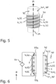
- Figures 5 and 6 show a further application example of a monolithic heating device 30 according to the invention, which in the example of Figures 5 and 6 serves to cool a cooling line 40 comprising a tubular body 41 and through which a cooling fluid can flow.
- Figure 5 shows a perspective view, Figure 6 a longitudinal section.
- the tubular body 41 has the geometry of a hollow cylinder with central longitudinal axis M extending along an axial direction A.
- On an outer circumference 42 of the tubular body 41 is arranged a multilayer structure 1 according to the invention with a likewise cylindrical geometric shape.
- an electrical conduction path 32 is also formed here by a resistive zone 4, which extends helically in the multilayer structure 1 around the tubular body 41 and thus forms a helix.
- the two path ends 33a, 33b are also electrically connected to an electrical voltage source 34 in this example.
- the resistive zone 4 is completely surrounded by a dielectric zone 3 for electrical insulation. Adjacent to the dielectric zone, radially inwardly, is an electrically conductive zone 2 with which the multilayer structure 1 rests on the outer circumference 42 of the tubular body 41. By means of the electrically conductive zone 2, good thermal contact of the zone 4 or the conductive path 32 with the tubular body 41 is ensured.
Landscapes
- Engineering & Computer Science (AREA)
- Chemical & Material Sciences (AREA)
- Materials Engineering (AREA)
- Manufacturing & Machinery (AREA)
- Automation & Control Theory (AREA)
- Mechanical Engineering (AREA)
- Metallurgy (AREA)
- Organic Chemistry (AREA)
- Resistance Heating (AREA)
Priority Applications (1)
| Application Number | Priority Date | Filing Date | Title |
|---|---|---|---|
| EP23175465.6A EP4467263A1 (fr) | 2023-05-25 | 2023-05-25 | Procédé de fabrication d'une structure multicouche à partir d'une poudre métallique par fusion à base de lit de poudre |
Applications Claiming Priority (1)
| Application Number | Priority Date | Filing Date | Title |
|---|---|---|---|
| EP23175465.6A EP4467263A1 (fr) | 2023-05-25 | 2023-05-25 | Procédé de fabrication d'une structure multicouche à partir d'une poudre métallique par fusion à base de lit de poudre |
Publications (1)
| Publication Number | Publication Date |
|---|---|
| EP4467263A1 true EP4467263A1 (fr) | 2024-11-27 |
Family
ID=86603798
Family Applications (1)
| Application Number | Title | Priority Date | Filing Date |
|---|---|---|---|
| EP23175465.6A Pending EP4467263A1 (fr) | 2023-05-25 | 2023-05-25 | Procédé de fabrication d'une structure multicouche à partir d'une poudre métallique par fusion à base de lit de poudre |
Country Status (1)
| Country | Link |
|---|---|
| EP (1) | EP4467263A1 (fr) |
Citations (4)
| Publication number | Priority date | Publication date | Assignee | Title |
|---|---|---|---|---|
| EP2963995A1 (fr) * | 2014-07-03 | 2016-01-06 | United Technologies Corporation | Ensemble de circuits de chauffage et procédé de fabrication |
| EP3442782A1 (fr) * | 2016-04-15 | 2019-02-20 | Hewlett-Packard Development Company, L.P. | Élément chauffant imprimé en 3 dimensions |
| US10830174B1 (en) * | 2019-05-21 | 2020-11-10 | General Electric Company | Monolithic heat-exchanger bodies |
| US20230058595A1 (en) * | 2020-01-23 | 2023-02-23 | Thales | Method for manufacturing a multi-material part by additive manufacturing, using the technique of powder bed selective laser melting or selective laser sintering |
-
2023
- 2023-05-25 EP EP23175465.6A patent/EP4467263A1/fr active Pending
Patent Citations (4)
| Publication number | Priority date | Publication date | Assignee | Title |
|---|---|---|---|---|
| EP2963995A1 (fr) * | 2014-07-03 | 2016-01-06 | United Technologies Corporation | Ensemble de circuits de chauffage et procédé de fabrication |
| EP3442782A1 (fr) * | 2016-04-15 | 2019-02-20 | Hewlett-Packard Development Company, L.P. | Élément chauffant imprimé en 3 dimensions |
| US10830174B1 (en) * | 2019-05-21 | 2020-11-10 | General Electric Company | Monolithic heat-exchanger bodies |
| US20230058595A1 (en) * | 2020-01-23 | 2023-02-23 | Thales | Method for manufacturing a multi-material part by additive manufacturing, using the technique of powder bed selective laser melting or selective laser sintering |
Similar Documents
| Publication | Publication Date | Title |
|---|---|---|
| JP6750953B2 (ja) | 高エネルギー源とホットワイヤを用いた付加製造のための方法とシステム | |
| CN106256930B (zh) | 陶瓷电子部件的制造方法以及陶瓷电子部件 | |
| JP3227602B2 (ja) | 溶接ワイヤ及びその製造方法 | |
| DE69619521T2 (de) | Elektrische heizelemente | |
| CN101589525B (zh) | 具有回流焊点火端头的点火装置及其构成方法 | |
| TWI593833B (zh) | 陶瓷電子零件之製造方法及陶瓷電子零件 | |
| DE102013215353A1 (de) | Schweissfügestellen bei einem stator und verfahren, um diese auszubilden | |
| EP4467263A1 (fr) | Procédé de fabrication d'une structure multicouche à partir d'une poudre métallique par fusion à base de lit de poudre | |
| CN116267027A (zh) | 火花塞电极及其制造方法 | |
| US20210243849A1 (en) | Ceramic heating resistor, electrical heating element, and device for heating a fluid | |
| JP6627734B2 (ja) | セラミック電子部品及びその製造方法 | |
| CN221150545U (zh) | 火花塞电极及火花塞 | |
| EP0615263B1 (fr) | Disjoncteur sous vide, disposition d'électrodes pour disjoncteur sous vide et méthode de fabrication | |
| JPH0630294B2 (ja) | 小型・非誘導性層状抵抗の製造方法 | |
| JP6694453B2 (ja) | 少なくとも2部品からなる構造体、特に超伝導線の半完成品を生成するための方法 | |
| US3400456A (en) | Methods of manufacturing thin film components | |
| CN109979791B (zh) | 一种阴极热子组件及其制作方法 | |
| CN112888516A (zh) | 用于在增材制造中使金属支撑结构脱离的方法 | |
| CN223987195U (zh) | 一种感应线圈 | |
| Tusek | A mathematical model for the melting rate in welding with a multiple-wire electrode | |
| JP2023009881A (ja) | 積層造形用金属粉末および誘導加熱コイル | |
| JPH02301938A (ja) | 進行波管 | |
| DE102020109032A1 (de) | Verfahren und Vorrichtung zur Erwärmung des Bauteils bei der Herstellung von pulvergeschmolzenen Bauteilen aus Metall | |
| JP2524859B2 (ja) | 抵抗・温度ヒュ―ズ並びにその製造方法 | |
| RU2841340C1 (ru) | Вольфрамовый нагреватель с экранами и способ его изготовления |
Legal Events
| Date | Code | Title | Description |
|---|---|---|---|
| PUAI | Public reference made under article 153(3) epc to a published international application that has entered the european phase |
Free format text: ORIGINAL CODE: 0009012 |
|
| STAA | Information on the status of an ep patent application or granted ep patent |
Free format text: STATUS: THE APPLICATION HAS BEEN PUBLISHED |
|
| AK | Designated contracting states |
Kind code of ref document: A1 Designated state(s): AL AT BE BG CH CY CZ DE DK EE ES FI FR GB GR HR HU IE IS IT LI LT LU LV MC ME MK MT NL NO PL PT RO RS SE SI SK SM TR |
|
| STAA | Information on the status of an ep patent application or granted ep patent |
Free format text: STATUS: REQUEST FOR EXAMINATION WAS MADE |
|
| 17P | Request for examination filed |
Effective date: 20250527 |