EP4467313A1 - Herstellung eines faserverstärkten verbundkörpers mit mehreren laminierten schichten - Google Patents
Herstellung eines faserverstärkten verbundkörpers mit mehreren laminierten schichten Download PDFInfo
- Publication number
- EP4467313A1 EP4467313A1 EP24178048.5A EP24178048A EP4467313A1 EP 4467313 A1 EP4467313 A1 EP 4467313A1 EP 24178048 A EP24178048 A EP 24178048A EP 4467313 A1 EP4467313 A1 EP 4467313A1
- Authority
- EP
- European Patent Office
- Prior art keywords
- fabric
- ply
- tool
- polymer matrix
- section
- Prior art date
- Legal status (The legal status is an assumption and is not a legal conclusion. Google has not performed a legal analysis and makes no representation as to the accuracy of the status listed.)
- Granted
Links
Images





Classifications
-
- B—PERFORMING OPERATIONS; TRANSPORTING
- B29—WORKING OF PLASTICS; WORKING OF SUBSTANCES IN A PLASTIC STATE IN GENERAL
- B29C—SHAPING OR JOINING OF PLASTICS; SHAPING OF MATERIAL IN A PLASTIC STATE, NOT OTHERWISE PROVIDED FOR; AFTER-TREATMENT OF THE SHAPED PRODUCTS, e.g. REPAIRING
- B29C70/00—Shaping composites, i.e. plastics material comprising reinforcements, fillers or preformed parts, e.g. inserts
- B29C70/04—Shaping composites, i.e. plastics material comprising reinforcements, fillers or preformed parts, e.g. inserts comprising reinforcements only, e.g. self-reinforcing plastics
- B29C70/06—Fibrous reinforcements only
- B29C70/10—Fibrous reinforcements only characterised by the structure of fibrous reinforcements, e.g. hollow fibres
- B29C70/16—Fibrous reinforcements only characterised by the structure of fibrous reinforcements, e.g. hollow fibres using fibres of substantial or continuous length
- B29C70/22—Fibrous reinforcements only characterised by the structure of fibrous reinforcements, e.g. hollow fibres using fibres of substantial or continuous length oriented in at least two directions forming a two-dimensional [2D] structure
-
- B—PERFORMING OPERATIONS; TRANSPORTING
- B29—WORKING OF PLASTICS; WORKING OF SUBSTANCES IN A PLASTIC STATE IN GENERAL
- B29B—PREPARATION OR PRETREATMENT OF THE MATERIAL TO BE SHAPED; MAKING GRANULES OR PREFORMS; RECOVERY OF PLASTICS OR OTHER CONSTITUENTS OF WASTE MATERIAL CONTAINING PLASTICS
- B29B11/00—Making preforms
- B29B11/14—Making preforms characterised by structure or composition
- B29B11/16—Making preforms characterised by structure or composition comprising fillers or reinforcement
-
- B—PERFORMING OPERATIONS; TRANSPORTING
- B29—WORKING OF PLASTICS; WORKING OF SUBSTANCES IN A PLASTIC STATE IN GENERAL
- B29C—SHAPING OR JOINING OF PLASTICS; SHAPING OF MATERIAL IN A PLASTIC STATE, NOT OTHERWISE PROVIDED FOR; AFTER-TREATMENT OF THE SHAPED PRODUCTS, e.g. REPAIRING
- B29C70/00—Shaping composites, i.e. plastics material comprising reinforcements, fillers or preformed parts, e.g. inserts
- B29C70/04—Shaping composites, i.e. plastics material comprising reinforcements, fillers or preformed parts, e.g. inserts comprising reinforcements only, e.g. self-reinforcing plastics
- B29C70/06—Fibrous reinforcements only
- B29C70/10—Fibrous reinforcements only characterised by the structure of fibrous reinforcements, e.g. hollow fibres
- B29C70/16—Fibrous reinforcements only characterised by the structure of fibrous reinforcements, e.g. hollow fibres using fibres of substantial or continuous length
-
- B—PERFORMING OPERATIONS; TRANSPORTING
- B29—WORKING OF PLASTICS; WORKING OF SUBSTANCES IN A PLASTIC STATE IN GENERAL
- B29C—SHAPING OR JOINING OF PLASTICS; SHAPING OF MATERIAL IN A PLASTIC STATE, NOT OTHERWISE PROVIDED FOR; AFTER-TREATMENT OF THE SHAPED PRODUCTS, e.g. REPAIRING
- B29C70/00—Shaping composites, i.e. plastics material comprising reinforcements, fillers or preformed parts, e.g. inserts
- B29C70/04—Shaping composites, i.e. plastics material comprising reinforcements, fillers or preformed parts, e.g. inserts comprising reinforcements only, e.g. self-reinforcing plastics
- B29C70/28—Shaping operations therefor
- B29C70/30—Shaping by lay-up, i.e. applying fibres, tape or broadsheet on a mould, former or core; Shaping by spray-up, i.e. spraying of fibres on a mould, former or core
-
- B—PERFORMING OPERATIONS; TRANSPORTING
- B29—WORKING OF PLASTICS; WORKING OF SUBSTANCES IN A PLASTIC STATE IN GENERAL
- B29C—SHAPING OR JOINING OF PLASTICS; SHAPING OF MATERIAL IN A PLASTIC STATE, NOT OTHERWISE PROVIDED FOR; AFTER-TREATMENT OF THE SHAPED PRODUCTS, e.g. REPAIRING
- B29C70/00—Shaping composites, i.e. plastics material comprising reinforcements, fillers or preformed parts, e.g. inserts
- B29C70/04—Shaping composites, i.e. plastics material comprising reinforcements, fillers or preformed parts, e.g. inserts comprising reinforcements only, e.g. self-reinforcing plastics
- B29C70/28—Shaping operations therefor
- B29C70/54—Component parts, details or accessories; Auxiliary operations, e.g. feeding or storage of prepregs or SMC after impregnation or during ageing
-
- B—PERFORMING OPERATIONS; TRANSPORTING
- B29—WORKING OF PLASTICS; WORKING OF SUBSTANCES IN A PLASTIC STATE IN GENERAL
- B29C—SHAPING OR JOINING OF PLASTICS; SHAPING OF MATERIAL IN A PLASTIC STATE, NOT OTHERWISE PROVIDED FOR; AFTER-TREATMENT OF THE SHAPED PRODUCTS, e.g. REPAIRING
- B29C70/00—Shaping composites, i.e. plastics material comprising reinforcements, fillers or preformed parts, e.g. inserts
- B29C70/04—Shaping composites, i.e. plastics material comprising reinforcements, fillers or preformed parts, e.g. inserts comprising reinforcements only, e.g. self-reinforcing plastics
- B29C70/28—Shaping operations therefor
- B29C70/54—Component parts, details or accessories; Auxiliary operations, e.g. feeding or storage of prepregs or SMC after impregnation or during ageing
- B29C70/545—Perforating, cutting or machining during or after moulding
-
- B—PERFORMING OPERATIONS; TRANSPORTING
- B29—WORKING OF PLASTICS; WORKING OF SUBSTANCES IN A PLASTIC STATE IN GENERAL
- B29C—SHAPING OR JOINING OF PLASTICS; SHAPING OF MATERIAL IN A PLASTIC STATE, NOT OTHERWISE PROVIDED FOR; AFTER-TREATMENT OF THE SHAPED PRODUCTS, e.g. REPAIRING
- B29C2793/00—Shaping techniques involving a cutting or machining operation
- B29C2793/0081—Shaping techniques involving a cutting or machining operation before shaping
-
- B—PERFORMING OPERATIONS; TRANSPORTING
- B29—WORKING OF PLASTICS; WORKING OF SUBSTANCES IN A PLASTIC STATE IN GENERAL
- B29C—SHAPING OR JOINING OF PLASTICS; SHAPING OF MATERIAL IN A PLASTIC STATE, NOT OTHERWISE PROVIDED FOR; AFTER-TREATMENT OF THE SHAPED PRODUCTS, e.g. REPAIRING
- B29C43/00—Compression moulding, i.e. applying external pressure to flow the moulding material; Apparatus therefor
- B29C43/02—Compression moulding, i.e. applying external pressure to flow the moulding material; Apparatus therefor of articles of definite length, i.e. discrete articles
-
- B—PERFORMING OPERATIONS; TRANSPORTING
- B29—WORKING OF PLASTICS; WORKING OF SUBSTANCES IN A PLASTIC STATE IN GENERAL
- B29C—SHAPING OR JOINING OF PLASTICS; SHAPING OF MATERIAL IN A PLASTIC STATE, NOT OTHERWISE PROVIDED FOR; AFTER-TREATMENT OF THE SHAPED PRODUCTS, e.g. REPAIRING
- B29C43/00—Compression moulding, i.e. applying external pressure to flow the moulding material; Apparatus therefor
- B29C43/32—Component parts, details or accessories; Auxiliary operations
- B29C43/36—Moulds for making articles of definite length, i.e. discrete articles
-
- B—PERFORMING OPERATIONS; TRANSPORTING
- B29—WORKING OF PLASTICS; WORKING OF SUBSTANCES IN A PLASTIC STATE IN GENERAL
- B29L—INDEXING SCHEME ASSOCIATED WITH SUBCLASS B29C, RELATING TO PARTICULAR ARTICLES
- B29L2031/00—Other particular articles
- B29L2031/30—Vehicles, e.g. ships or aircraft, or body parts thereof
- B29L2031/3076—Aircrafts
Definitions
- This disclosure relates generally to manufacturing and, more particularly, to manufacturing a fiber-reinforced composite body.
- a method for manufacturing an object includes: arranging a first portion of a fabric over a tool; cutting out a section of the first portion of the fabric to provide a first ply, and disposing the first ply on the tool; arranging a second portion of the fabric over the tool; cutting out a section of the second portion of the fabric to provide a second ply, and stacking the second ply on the first ply; and consolidating a laminate stack on the tool to form the object, the laminate stack including the first ply, the second ply and a polymer matrix impregnating the first ply and the second ply.
- this method includes: disposing a first portion of a fabric over a tool; cutting the first portion of the fabric to leave a first ply of the fabric on the tool; disposing a second portion of the fabric over the first ply of the fabric by moving a remnant of the first portion of the fabric following the cutting of the first portion of the fabric; cutting the second portion of the fabric to leave a second ply of the fabric on the first ply of the fabric; and consolidating a laminate stack on the tool, the laminate stack including the first ply of the fabric, the second ply of the fabric and a polymer matrix.
- this method includes: pulling a fabric off of a supply roll and over a tool; cutting the fabric using a robotic manipulator to leave a first ply of the fabric on the tool; further pulling the fabric off of the supply roll and over the first ply; cutting the fabric using the robotic manipulator to leave a second ply of the fabric on the first ply of the fabric; and consolidating a laminate stack, the laminate stack including the first ply of the fabric, the second ply of the fabric and a polymer matrix.
- the method may also include: drawing the first portion of the fabric and the second portion of the fabric from a supply roll of the fabric; and rolling up the remnant of the first portion of the fabric onto a remnant roll of the fabric.
- the section cut out of the first portion of the fabric may be an interior section of the first portion of the fabric.
- the method may also include: impregnating the first ply with the polymer matrix following the cutting out of the section of the first portion of the fabric; and impregnating the second ply with the polymer matrix following the cutting out of the section of the second portion of the fabric.
- the fabric may be or otherwise include a prepreg fabric.
- the prepreg fabric may include fiber-reinforcement impregnated with the polymer matrix.
- the polymer matrix may be or otherwise include a thermoset matrix.
- the polymer matrix may be or otherwise include a thermoplastic matrix.
- the arranging of the first portion of the fabric may include pulling the first portion of the fabric over the tool.
- the method may also include unrolling the fabric from a roll of the fabric during the pulling the first portion of the fabric over the tool.
- the method may also include rolling up a remnant of the fabric during the pulling the first portion of the fabric over the tool.
- the first portion of the fabric may be located between the remnant of the fabric and the second portion of the fabric.
- the method may also include removing a backer from the fabric during the pulling of the first portion of the fabric over the tool.
- the method may also include forming the fabric upstream of the tool along a manufacturing line.
- the forming of the fabric may include weaving fibers together.
- the section of the first portion of the fabric may be cut out using a knife attached to a robotic manipulator.
- the section of the first portion of the fabric may be cut out using an energy beam.
- the method may also include pressing the first ply against the tool.
- the method may also include re-orienting the tool following the disposing of the first ply on the tool and before the cutting out of the section of the second portion of the fabric.
- the method may also include pressing the laminate stack between the tool and a second tool.
- the object may be configured as a component for an aircraft.
- the present disclosure may include any one or more of the individual features disclosed above and/or below alone or in any combination thereof.
- the present disclosure includes systems and methods for manufacturing a fiber reinforced composite object.
- This composite object may be configured as a component of a propulsion system for an aircraft.
- the composite object for example, may be configured as a rotor blade or a stator vane.
- the rotor blade include a fan blade and an open rotor propulsor blade.
- the stator vane include an inlet guide vane and an exit guide vane.
- the composite object may be configured as or included as part of a structural support such as a strut, a frame or an engine case.
- the composite object may be configured as or included as part of a component of a nacelle housing an engine of the aircraft propulsion system.
- nacelle component examples include a liner, a nacelle barrel or a cowl.
- the composite object of the present disclosure is not limited to aircraft propulsion system applications.
- the composite object for example, may alternatively be configured as or included as part of another component for the aircraft; e.g., a component of a wing or a fuselage.
- the systems and methods of the present disclosure may also manufacture composite objects for non-aircraft applications.
- the composite object may be described below as an aircraft component such as a rotor blade.
- FIG. 1 illustrates an example of the composite object configured as a rotor blade 30; e.g., a propulsor blade such as a fan blade.
- This rotor blade 30 includes an airfoil 32 and a base 34 (e.g., a root, an attachment, etc.) for attaching the rotor blade 30 to a rotor disk or hub.
- the airfoil 32 is connected to the base 34.
- the airfoil 32 projects spanwise out from the base 34 along a span line 36 of the rotor blade 30 to a tip 38 of the airfoil 32.
- the airfoil 32 extends longitudinally along a camber line 40 of the airfoil 32 from a leading edge 42 of the airfoil 32 to a trailing edge 44 of the airfoil 32.
- the airfoil 32 has a thickness extending laterally between opposing sides 46 and 48 of the airfoil 32.
- the first side 46 may be a concave (e.g., pressure) side of the airfoil 32
- the second side 48 may be a convex (e.g., suction) side of the airfoil 32.
- the rotor blade 30 and its airfoil 32 are configured as a consolidated laminate.
- the rotor blade 30 of FIG. 3 and its airfoil 32 are formed from a plurality of fused layers 50A-H (generally referred to as "50") of material.
- Each of these layers 50 of material includes fiber-reinforcement and a polymer matrix 52.
- the fiber-reinforcement includes a plurality of fibers 54 such as fiberglass fibers, carbon fibers and/or aramid (e.g., Kevlar ® ) fibers.
- the fibers 54 within each layer 50 may be woven together into a (e.g., two-dimensional (2D)) weave such as a plain weave (see FIG.
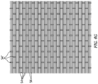
- the fibers 54 within one or more or all of the layers 50 may be non-woven (see FIG. 4G ); e.g., unidirectional.
- the unidirectional fibers 54 may be held together by light, non-structural weft fibers 54'.
- the woven fibers 54 are embedded within the polymer matrix 52.
- the polymer matrix 52 may thereby form a matrix about the fiber-reinforcement.
- the polymer matrix 52 may be a thermoset matrix or thermoplastic matrix.
- the thermoset matrix include, but are not limited to, Hexply ® M78, Hexply ® M91, polyvinyl acetate (PVA), polyvinyl butyral (PVB), UVECOAT ® , etc.
- the thermoplastic matrix include, but are not limited to, nylon, polyether ether ketone (PEEK), polyether ketone ketone (PEKK), acrylonitrile butadiene styrene (ABS), polycarbonate (PC), etc.
- the polymer matrix 52 may be pre-impregnated or added at a subsequent operation as described below in further detail.
- the weave of fibers 54 in one or more or all of the layers 50 may extend continuously (e.g., uninterrupted) between and to (e.g., all) opposing ends of the respective layer 50.
- the weave of fibers 54 in the layer 50 of FIG. 1 for example, extends longitudinally between and to (or about) the leading edge 42 and the trailing edge 44. This weave of fibers 54 also extends spanwise through the base 34 and the airfoil 32 to (or about) the tip 38.
- Providing such a continuous weave of fibers 54 longitudinally and spanwise across the rotor blade 30 may increase rotor blade strength compared to, for example, other arrangements with multiple different weaves of fibers (e.g., plies of fiber tape) disposed side-by-side next to one another and/or slightly overlapping one another within the same layer.
- fibers e.g., plies of fiber tape
- resin filled gaps between adjacent weaves and/or slight overlaps between adjacent weaves within a layer may impart weak points in that layer.
- the weaves of fibers 54 in different layers 50 may have different fiber orientations.
- the fibers 54 in the weave in a first layer 50A may be angularly offset to the fibers 54 in the weave in a (e.g., adjacent) second layer 50B.
- the fibers 54 in the first layer 50A of FIG. 5 are angularly offset from the fibers 54 in the second layer 50B by an included angle 56; e.g., an acute angle.
- the weaves of fibers 54 may have common (the same) fiber orientations.
- FIG. 6 is a flow diagram of a method 600 for manufacturing a composite object such as the rotor blade 30 of FIGS. 1-5 .
- the manufacturing method 600 is described below with reference to the manufacturing system of FIGS. 7-20 .
- the manufacturing method 600 of the present disclosure is not limited to utilizing such an exemplary manufacturing system.
- the manufacturing method 600 may also be utilized to manufacture various fiber reinforced composite objects other than the rotor blade 30 of FIGS. 1-5 .
- a length of fabric 58 is arranged with a fabric distribution system 60 of the manufacturing system.
- This fabric 58 may be a source for the weave of fibers 54 (e.g., piece of fabric) in some or all of the rotor blade layers 50; see FIGS. 3-5 .
- the fabric 58 includes the fiber-reinforcement fibers 54, which fibers 54 are woven into a continuous weave of the fibers 54; e.g., one of the weaves in FIGS. 4A-F .
- the fabric 58 may be a dry fabric where the fabric 58 has not yet been impregnated with the polymer matrix 52.
- the fabric 58 may be a prepreg fabric where the fabric 58 has been at least partially or fully pre-impregnated with the polymer matrix 52.
- the fabric 58 may be received in a supply roll 62; e.g., a fabric bolt.
- a supply roll 62 of the fabric 58 is rotatably mounted at (e.g., on, adjacent or proximate) a first side of a support device 64; e.g., a platform, a fixture, etc.
- the fabric 58 is partially unrolled from the supply roll 62 and pulled over and across the support device 64.
- a free end of the fabric 58 may then be attached to a remnant roll 66, which remnant roll 66 is rotatably mounted at a second side of the support device 64.
- an actuator 68 e.g., an electric motor.
- This actuator 68 may rotate the remnant roll 66 to roll up an initial portion of the fabric 58 onto the remnant roll 66.
- the rolling up of the fabric 58 onto the remnant roll 66 also pulls the fabric 58 along the support device 64 and pulls the fabric 58 off of the supply roll 62.
- the fabric distribution system 60 may also or alternatively include one or more other actuators to facilitate the movement of the fabric 58 along the support device 64 and/or the unrolling of the fabric 58 from the supply roll 62.
- a first tool 70 is arranged with the support device 64.
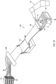
- This first tool 70 may be configured as a mold for forming the rotor blade 30.
- the first tool 70 of FIG. 7 for example, is configured as a bottom mold section; e.g., a bottom mold half.
- the first tool 70 is disposed on and may be fixed to the support device 64. With this arrangement, the fabric 58 is disposed over and extends across the first tool 70.
- an initial fabric ply 72 is provided using a cutting tool 74.
- the cutting tool 74 of FIG. 8 may cut out a (e.g., internal) section of a portion of the fabric 58 disposed over the first tool 70 to form the fabric ply 72.
- the fabric ply 72 may slightly fall onto and lay against the first tool 70. The cutting may thereby form the fabric ply 72 as well as facilitate disposing the cut fabric ply 72 on the first tool 70.
- the cutting tool 74 may be configured as a knife (e.g., a blade, an ultrasonic cutting knife, etc.) or an energy beam source (e.g., a laser).
- This cutting tool 74 may be an end effector attached to and moved by a multi-axis robotic manipulator 76; e.g., a robotic arm.
- step 608 referring to FIG. 10 , the fabric ply 72 is pressed against the first tool 70.
- a pressing device 78 such as a roller or a shoe, for example, may be pressed against and/or moved along the fabric ply 72 to compress the fabric ply 72 against the first tool 70.
- This pressing device 78 may be another end effector for the robotic manipulator 76.
- the robotic manipulator 76 may detach or index from the cutting tool 74 and attach or index to the pressing device 78 for performing the pressing step 608.
- the robotic manipulator 76 may be configured with an indexing head at an end of the robotic manipulator 76 which (e.g., automatically) indexes into position a select tool (e.g., a drag knife, a cutting wheel, an ultrasonic knife, a roller, a shoe, a laser, a matrix jetting head, etc.).
- a select tool e.g., a drag knife, a cutting wheel, an ultrasonic knife, a roller, a shoe, a laser, a matrix jetting head, etc.
- the fabric ply 72 may be partially or fully impregnated with the polymer matrix 52.
- a matrix applicator 80 such as a nozzle or a jetting head, for example, may direct the polymer matrix 52 onto the fabric ply 72.
- This polymer matrix 52 may be applied to wet the fabric ply 72 where the fabric 58 is the dry fabric.
- the polymer matrix 52 may also be applied to provide additional polymer matrix 52 for subsequent lamination even where the fabric 58 is the prepreg fabric.
- this matrix application step 610 may be omitted when the fabric 58 is the prepreg fabric and already includes a suitable amount of the polymer matrix 52 for subsequent lamination.
- the matrix applicator 80 may be another end effector for the robotic manipulator 76.
- the robotic manipulator 76 may detach or index from the pressing device 78 and attach or index to the matrix applicator 80 for performing the matrix application step 610.
- the polymer matrix 52 may be at least partially (or fully) cured.
- An ultraviolet (UV) light source 82 may direct ultraviolet radiation onto the polymer matrix 52 to facilitate partial or full matrix curing; e.g., where the polymer matrix 52 is a UV curing matrix.
- the light source 82 may be another end effector for the robotic manipulator 76.
- the robotic manipulator 76 may detach or index from the matrix applicator 80 (or the pressing device 78) and attach or index to the light source 82 for performing the curing step 612.
- this ultraviolet light curing step 612 may be omitted when, for example, layer-by-layer curing is not necessary.
- step 614 referring to FIG. 13 , another (e.g., uncut) portion of the fabric 58 is arranged over the first tool 70 and the previously formed fabric ply 72.
- the actuator 68 may rotate the remnant roll 66 to roll up remnants 84 of the fabric 58 following the cutting step 606 onto the remnant roll 66.
- the rolling up of the fabric 58 onto the remnant roll 66 also pulls the uncut fabric 58 off of the supply roll 62, along the support device 64 and over the first tool 70 as well as the previously formed fabric ply 72.
- the support device 64 may also be lowered to make room for the previously cut fabric ply 72 between the first tool 70 and the next (e.g., uncut) portion of the fabric 58.
- step 616 referring to FIG. 14 , another fabric ply 86 is provided using the cutting tool 74.
- the cutting tool 74 of FIG. 14 may cut out a (e.g., internal) section of another (e.g., uncut) portion of the fabric 58 disposed over the first tool 70 to form the fabric ply 86.
- the fabric ply 86 may slightly fall onto and lay against the previously formed fabric ply 72 / over the first tool 70. The cutting may thereby form the fabric ply 86 as well as facilitate disposing the cut fabric ply 86 on the formed fabric ply 72 / over the first tool 70.
- step 618 one or more of the steps 608, 610 and/or 612 may be performed for the fabric ply 86.
- step 620 the steps 616 and 618 may be performed one or more additional times to provide a laminate stack.
- the laminate stack 88 is consolidated on the first tool 70.
- a second tool 90 for example, may be arranged on top of the laminate stack 88 and the first tool 70.
- This second tool 90 of FIG. 16 is configured as a top mold section; e.g., a top mold half.
- the robotic manipulator 76 or another device may place the second tool 90 over the laminate stack 88 for mating with the first tool 70.
- the laminate stack 88 may be pressed between the first tool 70 and the second tool 90, for example, using a mold press.
- the first tool 70 with the laminate stack 88 may be removed from the support device 64 and vacuum bagged using traditional techniques.
- the laminate stack 88 may then be heated (e.g., in a furnace 92 such as an autoclave, an oven or other thermal-processing equipment) while under pressure to fuse the impregnated fabric plies (e.g., 72 and 86) together and cure the polymer matrix 52.
- the consolidated laminate stack 88 may form the rotor blade 30, or form a preform of the rotor blade 30 where additional finishing operations are to be performed.
- the laminate stack 88 may be consolidated after a certain number (e.g., 4-5) of plies have been stacked, and the process can be repeated to form the rotor blade 30 or the preform.
- the support device 64 may rotate about an axis 94 to reorient the first tool 70 relative to the fabric 58.
- a direction of the fibers 54 (see FIG. 5 ) within the fabric 58 may be reoriented relative to the first tool 70.
- fiber orientation may be tailored (e.g., changed or not) on a layer-by-layer basis.
- one or more surfaces 96 and 98 of the fabric 58 in the supply roll 62 may each be protected by a respective backer 100 and 102.
- Each backer 100, 102 may be removed from the fabric 58 as it is pulled toward the first tool 70.
- Each backer 100, 102 may be attached to a backer removal roller 104, 106.
- Each backer removal roller 104, 106 may be rotated with the rotating of the remnant roll 66 to pull the respective backer 100, 102 off of the fabric 58.
- the supply roll 62 of the fabric 58 may be one of multiple supply rolls 62 available for use in an automated material carousel 108. With such an arrangement, different rolls of fabric may be selected based on the specific composite object being formed. These different rolls of fabric may include different types of fabric materials, different weave patterns and/or different dimensions (e.g., thicknesses, widths, etc.).
- a loom 109 (e.g., a Jacquard loom) may be provided to form the fabric 58 upstream of the first tool 70 along a (e.g., continuous) manufacturing line 110 using lengths of fiber on spools 111.
- the fabric 58 may be dipped into an impregnation bath 112 to partially or fully impregnate the fibers with the polymer matrix 52. This impregnation step may be repeated multiple times to build up adhesive as needed.
- the impregnated fabric 58 prepare fabric
- each processing step may be automatically performed along a common (the same) manufacturing line 110. This may also reduce the need for cold storage for rolls of prepreg fabric.
- the manufacturing system may include one or more conveyors 114 for automatically delivering prepared tools 70 to the support device 64 as well as delivering the laminate stack 88 to the furnace 92 (e.g., the autoclave, the oven or the other thermal-processing equipment) for consolidation.
- the one or more conveyors 114 may also be added to the manufacturing system of FIG. 18 and/or FIG. 19 .
Landscapes
- Engineering & Computer Science (AREA)
- Mechanical Engineering (AREA)
- Chemical & Material Sciences (AREA)
- Composite Materials (AREA)
- Textile Engineering (AREA)
- Moulding By Coating Moulds (AREA)
Applications Claiming Priority (1)
| Application Number | Priority Date | Filing Date | Title |
|---|---|---|---|
| US18/202,760 US12528258B2 (en) | 2023-05-26 | 2023-05-26 | Manufacturing fiber-reinforced composite body with multiple laminated layers |
Publications (2)
| Publication Number | Publication Date |
|---|---|
| EP4467313A1 true EP4467313A1 (de) | 2024-11-27 |
| EP4467313B1 EP4467313B1 (de) | 2026-04-08 |
Family
ID=91247266
Family Applications (1)
| Application Number | Title | Priority Date | Filing Date |
|---|---|---|---|
| EP24178048.5A Active EP4467313B1 (de) | 2023-05-26 | 2024-05-24 | Herstellung eines faserverstärkten verbundkörpers mit mehreren laminierten schichten |
Country Status (2)
| Country | Link |
|---|---|
| US (1) | US12528258B2 (de) |
| EP (1) | EP4467313B1 (de) |
Citations (3)
| Publication number | Priority date | Publication date | Assignee | Title |
|---|---|---|---|---|
| GB2268705A (en) * | 1992-07-16 | 1994-01-19 | British Aerospace | Layup preparation for fibre reinforced composites |
| WO1996027701A1 (en) * | 1995-03-08 | 1996-09-12 | Toray Industries, Inc. | Reinforced woven material and method and apparatus for manufacturing the same |
| US11155048B2 (en) * | 2018-07-10 | 2021-10-26 | Bell Helicopter Textron Inc. | Material dispensing systems |
Family Cites Families (5)
| Publication number | Priority date | Publication date | Assignee | Title |
|---|---|---|---|---|
| US9969131B2 (en) | 2011-06-22 | 2018-05-15 | The Boeing Company | Automated ply layup system |
| US11440652B2 (en) * | 2018-08-07 | 2022-09-13 | Textron Innovations Inc. | All-fabric spar for aerodynamic components |
| FR3101569B1 (fr) | 2019-10-08 | 2021-09-10 | Safran Nacelles | Machine de drapage et de compactage automatique |
| US11618248B2 (en) | 2020-07-13 | 2023-04-04 | Southwest Research Institute | End of arm tool (EOAT) for layup of pre-impregnated composite laminates and robotic arm control system and method |
| GB2622323B (en) * | 2022-04-11 | 2025-02-12 | Prf Composite Holdings Ltd | Reinforcement Material For Composite Laminate |
-
2023
- 2023-05-26 US US18/202,760 patent/US12528258B2/en active Active
-
2024
- 2024-05-24 EP EP24178048.5A patent/EP4467313B1/de active Active
Patent Citations (3)
| Publication number | Priority date | Publication date | Assignee | Title |
|---|---|---|---|---|
| GB2268705A (en) * | 1992-07-16 | 1994-01-19 | British Aerospace | Layup preparation for fibre reinforced composites |
| WO1996027701A1 (en) * | 1995-03-08 | 1996-09-12 | Toray Industries, Inc. | Reinforced woven material and method and apparatus for manufacturing the same |
| US11155048B2 (en) * | 2018-07-10 | 2021-10-26 | Bell Helicopter Textron Inc. | Material dispensing systems |
Also Published As
| Publication number | Publication date |
|---|---|
| US20240391183A1 (en) | 2024-11-28 |
| EP4467313B1 (de) | 2026-04-08 |
| US12528258B2 (en) | 2026-01-20 |
Similar Documents
| Publication | Publication Date | Title |
|---|---|---|
| EP1995045B1 (de) | Vorgefertigter Auflegesatz und Herstellungsverfahren | |
| EP2441571B1 (de) | Verfahren zur Herstellung eines faserverbundbauteils | |
| CN108725749B (zh) | 纤维增强复合材料翼型件结构 | |
| US11746673B2 (en) | Manufacture of a fan track liner | |
| Mills | Automation of carbon fibre preform manufacture for affordable aerospace applications | |
| EP2283995B1 (de) | Verfahren zur Herstellung mindestens einer Komponente einer Windturbinenschaufel | |
| EP2698317A2 (de) | Verbundvorflügel für Luftfahrzeug | |
| JP2011518068A (ja) | 輪郭に合致した複合構造物を生産する方法及びその方法によって生産される構造物 | |
| CN114206722A (zh) | 集成拉挤成型复合型材及用于制造其的方法 | |
| EP3093121A1 (de) | Flugzeugkomponente mit geschlossener struktur | |
| CN105408079B (zh) | 生产热塑性纤维复合物的工艺及从其形成的风扇叶片 | |
| US11820087B2 (en) | Material dispensing systems | |
| EP3919370B1 (de) | Flugzeugversteifungen mit durch cfk-material verstärkten gurten | |
| CA2606810C (en) | Method for the manufacturing of a hollow fiber reinforced structural member | |
| US20240227320A9 (en) | Method for manufacturing a composite part and preform for manufacturing same | |
| EP4467313B1 (de) | Herstellung eines faserverstärkten verbundkörpers mit mehreren laminierten schichten | |
| EP3868548B1 (de) | Verfahren zur herstellung von soliden laminatstringern auf einer verbundplatte | |
| US12624175B2 (en) | Reinforcement material for composite laminate | |
| Mills | Development of an automated preforming technology for resin infusion processing of aircraft components | |
| US20240003329A1 (en) | Composite thermoplastic rotor blade with integral cuff | |
| Mills | Manufacturing technology development foraerospace composite structures | |
| CA2521125C (en) | Apparatus and methods for fabricating a helicopter main rotor blade |
Legal Events
| Date | Code | Title | Description |
|---|---|---|---|
| PUAI | Public reference made under article 153(3) epc to a published international application that has entered the european phase |
Free format text: ORIGINAL CODE: 0009012 |
|
| STAA | Information on the status of an ep patent application or granted ep patent |
Free format text: STATUS: THE APPLICATION HAS BEEN PUBLISHED |
|
| AK | Designated contracting states |
Kind code of ref document: A1 Designated state(s): AL AT BE BG CH CY CZ DE DK EE ES FI FR GB GR HR HU IE IS IT LI LT LU LV MC ME MK MT NL NO PL PT RO RS SE SI SK SM TR |
|
| STAA | Information on the status of an ep patent application or granted ep patent |
Free format text: STATUS: REQUEST FOR EXAMINATION WAS MADE |
|
| 17P | Request for examination filed |
Effective date: 20250527 |
|
| REG | Reference to a national code |
Ref country code: DE Ref legal event code: R079 Free format text: PREVIOUS MAIN CLASS: B29C0043360000 Ipc: B29C0043020000 Ref document number: 602024003759 Country of ref document: DE |
|
| GRAP | Despatch of communication of intention to grant a patent |
Free format text: ORIGINAL CODE: EPIDOSNIGR1 |
|
| STAA | Information on the status of an ep patent application or granted ep patent |
Free format text: STATUS: GRANT OF PATENT IS INTENDED |
|
| RIC1 | Information provided on ipc code assigned before grant |
Ipc: B29C 43/02 20060101AFI20250929BHEP Ipc: B29C 70/30 20060101ALI20250929BHEP Ipc: B29C 70/54 20060101ALI20250929BHEP Ipc: B29B 11/16 20060101ALI20250929BHEP Ipc: B29C 70/16 20060101ALI20250929BHEP Ipc: B29C 43/36 20060101ALI20250929BHEP |
|
| INTG | Intention to grant announced |
Effective date: 20251104 |
|
| GRAS | Grant fee paid |
Free format text: ORIGINAL CODE: EPIDOSNIGR3 |
|
| GRAA | (expected) grant |
Free format text: ORIGINAL CODE: 0009210 |
|
| STAA | Information on the status of an ep patent application or granted ep patent |
Free format text: STATUS: THE PATENT HAS BEEN GRANTED |
|
| AK | Designated contracting states |
Kind code of ref document: B1 Designated state(s): AL AT BE BG CH CY CZ DE DK EE ES FI FR GB GR HR HU IE IS IT LI LT LU LV MC ME MK MT NL NO PL PT RO RS SE SI SK SM TR |
|
| REG | Reference to a national code |
Ref country code: CH Ref legal event code: F10 Free format text: ST27 STATUS EVENT CODE: U-0-0-F10-F00 (AS PROVIDED BY THE NATIONAL OFFICE) Effective date: 20260408 Ref country code: GB Ref legal event code: FG4D |
|
| REG | Reference to a national code |
Ref country code: DE Ref legal event code: R096 Ref document number: 602024003759 Country of ref document: DE |