EP4467383A1 - Système d'alimentation à courants multiples pour un véhicule ferroviaire - Google Patents
Système d'alimentation à courants multiples pour un véhicule ferroviaire Download PDFInfo
- Publication number
- EP4467383A1 EP4467383A1 EP23382492.9A EP23382492A EP4467383A1 EP 4467383 A1 EP4467383 A1 EP 4467383A1 EP 23382492 A EP23382492 A EP 23382492A EP 4467383 A1 EP4467383 A1 EP 4467383A1
- Authority
- EP
- European Patent Office
- Prior art keywords
- power supply
- fault
- block
- supply system
- selector
- Prior art date
- Legal status (The legal status is an assumption and is not a legal conclusion. Google has not performed a legal analysis and makes no representation as to the accuracy of the status listed.)
- Pending
Links
- 238000004804 winding Methods 0.000 claims description 25
- 230000008859 change Effects 0.000 claims description 8
- 230000008878 coupling Effects 0.000 claims description 6
- 238000010168 coupling process Methods 0.000 claims description 6
- 238000005859 coupling reaction Methods 0.000 claims description 6
- 230000001419 dependent effect Effects 0.000 claims description 4
- 238000001914 filtration Methods 0.000 claims description 4
- 239000003990 capacitor Substances 0.000 claims description 2
- 238000001514 detection method Methods 0.000 description 2
- 230000009467 reduction Effects 0.000 description 2
- 238000006243 chemical reaction Methods 0.000 description 1
- 238000010348 incorporation Methods 0.000 description 1
Images



Classifications
-
- B—PERFORMING OPERATIONS; TRANSPORTING
- B60—VEHICLES IN GENERAL
- B60L—PROPULSION OF ELECTRICALLY-PROPELLED VEHICLES; SUPPLYING ELECTRIC POWER FOR AUXILIARY EQUIPMENT OF ELECTRICALLY-PROPELLED VEHICLES; ELECTRODYNAMIC BRAKE SYSTEMS FOR VEHICLES IN GENERAL; MAGNETIC SUSPENSION OR LEVITATION FOR VEHICLES; MONITORING OPERATING VARIABLES OF ELECTRICALLY-PROPELLED VEHICLES; ELECTRIC SAFETY DEVICES FOR ELECTRICALLY-PROPELLED VEHICLES
- B60L9/00—Electric propulsion with power supply external to the vehicle
- B60L9/16—Electric propulsion with power supply external to the vehicle using AC induction motors
- B60L9/18—Electric propulsion with power supply external to the vehicle using AC induction motors fed from DC supply lines
- B60L9/22—Electric propulsion with power supply external to the vehicle using AC induction motors fed from DC supply lines polyphase motors
-
- B—PERFORMING OPERATIONS; TRANSPORTING
- B60—VEHICLES IN GENERAL
- B60L—PROPULSION OF ELECTRICALLY-PROPELLED VEHICLES; SUPPLYING ELECTRIC POWER FOR AUXILIARY EQUIPMENT OF ELECTRICALLY-PROPELLED VEHICLES; ELECTRODYNAMIC BRAKE SYSTEMS FOR VEHICLES IN GENERAL; MAGNETIC SUSPENSION OR LEVITATION FOR VEHICLES; MONITORING OPERATING VARIABLES OF ELECTRICALLY-PROPELLED VEHICLES; ELECTRIC SAFETY DEVICES FOR ELECTRICALLY-PROPELLED VEHICLES
- B60L3/00—Electric devices on electrically-propelled vehicles for safety purposes; Monitoring operating variables, e.g. speed, deceleration or energy consumption
- B60L3/0023—Detecting, eliminating, remedying or compensating for drive train abnormalities, e.g. failures within the drive train
-
- B—PERFORMING OPERATIONS; TRANSPORTING
- B60—VEHICLES IN GENERAL
- B60L—PROPULSION OF ELECTRICALLY-PROPELLED VEHICLES; SUPPLYING ELECTRIC POWER FOR AUXILIARY EQUIPMENT OF ELECTRICALLY-PROPELLED VEHICLES; ELECTRODYNAMIC BRAKE SYSTEMS FOR VEHICLES IN GENERAL; MAGNETIC SUSPENSION OR LEVITATION FOR VEHICLES; MONITORING OPERATING VARIABLES OF ELECTRICALLY-PROPELLED VEHICLES; ELECTRIC SAFETY DEVICES FOR ELECTRICALLY-PROPELLED VEHICLES
- B60L3/00—Electric devices on electrically-propelled vehicles for safety purposes; Monitoring operating variables, e.g. speed, deceleration or energy consumption
- B60L3/0023—Detecting, eliminating, remedying or compensating for drive train abnormalities, e.g. failures within the drive train
- B60L3/003—Detecting, eliminating, remedying or compensating for drive train abnormalities, e.g. failures within the drive train relating to inverters
-
- B—PERFORMING OPERATIONS; TRANSPORTING
- B60—VEHICLES IN GENERAL
- B60L—PROPULSION OF ELECTRICALLY-PROPELLED VEHICLES; SUPPLYING ELECTRIC POWER FOR AUXILIARY EQUIPMENT OF ELECTRICALLY-PROPELLED VEHICLES; ELECTRODYNAMIC BRAKE SYSTEMS FOR VEHICLES IN GENERAL; MAGNETIC SUSPENSION OR LEVITATION FOR VEHICLES; MONITORING OPERATING VARIABLES OF ELECTRICALLY-PROPELLED VEHICLES; ELECTRIC SAFETY DEVICES FOR ELECTRICALLY-PROPELLED VEHICLES
- B60L3/00—Electric devices on electrically-propelled vehicles for safety purposes; Monitoring operating variables, e.g. speed, deceleration or energy consumption
- B60L3/0092—Electric devices on electrically-propelled vehicles for safety purposes; Monitoring operating variables, e.g. speed, deceleration or energy consumption with use of redundant elements for safety purposes
-
- B—PERFORMING OPERATIONS; TRANSPORTING
- B60—VEHICLES IN GENERAL
- B60L—PROPULSION OF ELECTRICALLY-PROPELLED VEHICLES; SUPPLYING ELECTRIC POWER FOR AUXILIARY EQUIPMENT OF ELECTRICALLY-PROPELLED VEHICLES; ELECTRODYNAMIC BRAKE SYSTEMS FOR VEHICLES IN GENERAL; MAGNETIC SUSPENSION OR LEVITATION FOR VEHICLES; MONITORING OPERATING VARIABLES OF ELECTRICALLY-PROPELLED VEHICLES; ELECTRIC SAFETY DEVICES FOR ELECTRICALLY-PROPELLED VEHICLES
- B60L9/00—Electric propulsion with power supply external to the vehicle
- B60L9/16—Electric propulsion with power supply external to the vehicle using AC induction motors
- B60L9/24—Electric propulsion with power supply external to the vehicle using AC induction motors fed from AC supply lines
- B60L9/28—Electric propulsion with power supply external to the vehicle using AC induction motors fed from AC supply lines polyphase motors
-
- B—PERFORMING OPERATIONS; TRANSPORTING
- B60—VEHICLES IN GENERAL
- B60L—PROPULSION OF ELECTRICALLY-PROPELLED VEHICLES; SUPPLYING ELECTRIC POWER FOR AUXILIARY EQUIPMENT OF ELECTRICALLY-PROPELLED VEHICLES; ELECTRODYNAMIC BRAKE SYSTEMS FOR VEHICLES IN GENERAL; MAGNETIC SUSPENSION OR LEVITATION FOR VEHICLES; MONITORING OPERATING VARIABLES OF ELECTRICALLY-PROPELLED VEHICLES; ELECTRIC SAFETY DEVICES FOR ELECTRICALLY-PROPELLED VEHICLES
- B60L9/00—Electric propulsion with power supply external to the vehicle
- B60L9/16—Electric propulsion with power supply external to the vehicle using AC induction motors
- B60L9/30—Electric propulsion with power supply external to the vehicle using AC induction motors fed from different kinds of power-supply lines
-
- B—PERFORMING OPERATIONS; TRANSPORTING
- B60—VEHICLES IN GENERAL
- B60L—PROPULSION OF ELECTRICALLY-PROPELLED VEHICLES; SUPPLYING ELECTRIC POWER FOR AUXILIARY EQUIPMENT OF ELECTRICALLY-PROPELLED VEHICLES; ELECTRODYNAMIC BRAKE SYSTEMS FOR VEHICLES IN GENERAL; MAGNETIC SUSPENSION OR LEVITATION FOR VEHICLES; MONITORING OPERATING VARIABLES OF ELECTRICALLY-PROPELLED VEHICLES; ELECTRIC SAFETY DEVICES FOR ELECTRICALLY-PROPELLED VEHICLES
- B60L2220/00—Electrical machine types; Structures or applications thereof
- B60L2220/40—Electrical machine applications
- B60L2220/42—Electrical machine applications with use of more than one motor
Definitions
- the present invention relates to multi-current power supply systems configured to be arranged in a railway vehicle, whereby said railway vehicle can be electrically powered with different types of power supplies as required.
- Electric railway vehicles are powered by at least one three-phase electric motor which is fed from the electric power supplied by a catenary.
- the vehicle comprises a power supply system configured to be connected to the catenary and which converts the voltage from the catenary into the appropriate voltage for the motor.
- some vehicles include power supply systems adapted to be able to connect to different types of catenaries (multi-current power supply systems).
- the voltage may be of a certain value, on another section this value may be different.
- the catenary may have different voltage types, i.e. the catenary may be direct current in some cases and alternating current in other cases: to connect to an alternating current catenary, the power supply system requires a traction transformer connectable to the catenary to convert the power supply to the catenary to the levels required for the vehicle; and to connect to a direct current catenary, however, this system does not require a traction transformer but an inductance. If necessary, it may be the case that a transformer can operate as an inductance by configuring the transformer in a particular way, so it is not uncommon for all or most power supply systems to comprise at least one transformer.
- EP3019366A2 discloses a multi-current power supply system for railway vehicles.
- the power supply system is configured to electrically power a plurality of electric motors of the railway vehicle, and comprises a plurality of motor outputs, each motor output being configured to couple to one of the motors of the railway vehicle; a first connection point and a second connection point for connection to a catenary; a power selector configured to connect the first connection point or the second connection point to a catenary; and a transformer comprising a primary winding to which the first connection point is connected, and at least one secondary winding associated with each motor output, the second connection point being connected to the secondary windings of the transformer.
- the power supply system disclosed in EP3019366A2 further comprises, for each motor output, a DC bus between a secondary winding of the transformer and the corresponding motor output; a converter block connected between said secondary winding of the transformer and said DC bus, and configured to transform the catenary voltage received through the transformer into a DC voltage for said DC bus; and an inverter connected between the DC bus and the corresponding system output, and configured to transform the DC bus voltage into a three-phase AC voltage for the motor coupled to said system output.
- the object of the invention is to provide a multi-current power supply system for a railway vehicle comprising at least two electric motors, as defined in the claims.
- the power supply system is configured to be able to electrically supply the vehicle's motors from different power supply lines, and comprises a first connection point and a second connection point for connecting said power supply system to a catenary; a power supply selector configured to connect the first connection point or the second connection point to a catenary, the power supply system receiving the electrical supply from the catenary to which it is connected; a transformer comprising a primary winding to which the first connection point is connected, and two secondary windings for each of two vehicle motors; and at least one power supply unit connected to two secondary windings.
- the power pack comprises a first motor output for coupling to a first motor, a second motor output for coupling to a second motor, a DC bus with two poles, a first load-side converter connected to the DC bus and to the first motor output and configured to transform a DC voltage from the DC bus to an AC voltage for powering the first motor, and a second load-side converter connected to the DC bus and to the second motor output and configured to transform a DC voltage from the DC bus to an AC voltage for powering the second motor, and a respective line-side converter connected to a corresponding secondary winding of the transformer and to the DC bus and comprising a first output terminal and a second output terminal.
- a first pole of the DC bus is connected to the first output terminal of a first line-side converter, and a second pole of the DC bus is connected to the second output terminal of a second line-side converter.
- the second output terminal of the first line-side converter is connected to the first output terminal of the second line-side converter, such that the two line-side converters of the power system block are cascaded.
- the cascade connection allows the power supply system to switch from being fed from an AC voltage catenary or power supply line to a DC voltage catenary or power supply line in a simple manner, since it is the cascade connection itself that provides an intermediate reference point for balancing the voltages.
- Figure 1 shows an embodiment of the proposed multi-current power supply system 1.
- the power supply system 1 is configured to be arranged on a railway vehicle 100, and to electrically power a plurality of electric motors 200.1 to 200.4 of said vehicle 100 depicted by way of example in figure 2 .
- the power supply system 1 comprises a first connection point 1.1 and a second connection point 1.2 for connecting said power supply system 1 to a catenary 300 (to a power line); a power selector 1.3 configured to connect one of the two connection points 1.1 or 1.2 to a catenary 300; a transformer 2 comprising a primary winding 2.1 to which the first connection point 1.1 is connected and two secondary windings 2.2 for each of two motors 200.1 and 200.4; 200.2 and 200.3; and at least one power supply block 8 connected to two secondary windings 2.2 and depicted in figure 3 , for each of two motors 200.1 and 200.4; 200.2 and 200.3 of the vehicle 100, such that said power supply block 8 comprises a first motor output 5.1 for coupling to one motor 200.1; 200.2 and a second motor output 5.2 for coupling to another motor 200.3; 200.4.
- the power supply block 8 further comprises a DC bus 3 with two poles 3.1 and 3.2, a first line-side converter 4 connected to a first secondary winding 2.2 of the transformer 2 and a second line-side converter 4 connected to a second secondary winding 2.2 of the transformer 2, said line-side converters 4 being preferably connected to the secondary windings 2.2 via the power supply selector 1.3, which in one position keeps said line-side converters 4 electrically connected to the secondary windings 2.2 through the power supply selector 1.3 so that said line-side converters 4 receive power through the first connection point 1.1 and which in another position disables this connection and electrically connects the line-side converters 4 to the second connection point 1.2.
- the power supply block 8 further comprises a first load-side converter 6 connected to its first motor output 5.1 and a second load-side converter 6 connected to its second motor output 5.2, each load-side converter 6 being connected to the DC bus 3 and configured to adapt a DC voltage from said DC bus 3 to an AC voltage for powering the corresponding motor 200.1 to 200.4.
- Each line-side converter 4 comprises a first output terminal 4.1 and a second output terminal 4.2.
- the second output terminal 4.2 of the first line-side converter 4 is connected to the first output terminal 4.1 of the second line-side converter 4, such that the line-side converters 4 of the power supply block 8 are cascaded, as depicted in more detail in Figure 4 , requiring a smaller size compared to using converters of another topology common in this sector, such as NPC topology.
- the reduction in size obtained in comparison to the state of the art can be used to incorporate additional functions in the power supply system 1 without increasing the size compared to using a standard topology such as the NPC, for example, as detailed below.
- Each line-side converter 4 is a full bridge converter (H-bridge), and this together with the fact of using a cascaded topology to link two line-side converters 4 allows or facilitates connecting to the DC bus 3 additional elements or devices that provide additional functionalities to the power system 1 (mainly due to the absence of diodes in contrast to what happens in the NPC topology).
- H-bridge full bridge converter
- the additional elements or devices may comprise a braking chopper 7 (see figure 1 ) for example. Thanks to the braking chopper 7 the energy generated during braking of the vehicle 100 can be dissipated by a heatsink 12 (see figure 1 ).
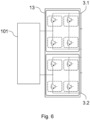
- the power supply block 8 comprises a DC - DC converter 13 to provide this additional function, and said DC - DC converter 13 is connected between the first line-side converter 4 and the battery 101 (as shown in figure 5 ).
- the DC - DC converter 13 may have a conventional or any required configuration, but thanks to the cascading of the two line-side converters 4, the DC - DC converter 13 may comprise a configuration analogous to such a cascaded assembly, as shown in figure 6 .
- the additional elements or devices may include a DC/DC converter connected to DC bus 3 and not shown in the figures, to power the auxiliary loads of the vehicle 100.
- the different catenaries 300 to which the power supply system 1 has to cope with and be able to connect comprise AC voltage catenaries 300 and also DC voltage catenaries 300 with different voltage values.
- the catenaries 300 may comprise different voltage values, and the power supply system 1 has to be adapted to adapt to the different possible voltages it has to cope with.
- the power supply system 1 comprises a transformer 2 which has already been mentioned and by means of which the power supply system 1 is adapted to operate with AC voltages of different values.
- the problem may arise when the voltage of the DC catenary 300 is at the lower end of the possible voltage range. In this case, it is necessary to raise the voltage of the catenary 300 to supply the motors 200.1 to 200.4, in order to obtain a DC bus 3 suitable for supplying the corresponding load-side converters 6.
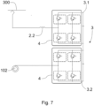
- the voltage can be easily raised, since it simply requires a certain configuration of the power supply selector 1.3 which allows, for example, the catenary 300 to be connected through one of the secondary windings 2.2 associated with the power supply block 8, as shown in figure 7 as an example.
- each load-side converter 6 comprises a NPC ("Neutral-Point Clamped") topology, as shown as an example in figure 8 , of at least three levels, and are connected in parallel on the DC side (on the side that they are connected to the DC bus 3).
- NPC Neutral-Point Clamped
- the power supply system 1 retains the advantages described by cascading the line-side converters 4, but achieves high voltage conversion efficiency for each of the motor outputs 5.1 and 5.2 because each load-side converter 6 is a multilevel converter.
- each line-side converter 4 and/or each load-side converter 6 comprise a plurality of controllable switches 4.3 and 6.3 (which may be, for example, IGBTs).
- the power system 1 comprises a control device 19 configured to control said controllable switches 4.3 and 6.3.
- Said control device 19 may further be in communication with the power selector 1.3 and configured to cause a change of position of said power selector 1.3, although the change of position of said power selector 1.3 could also, or alternatively, be done manually.
- the power supply block 8 further comprises a DC bus 3 with a first pole 3.1 connected to the first output terminal 4.1 of the first line-side converter 4 and a second pole 3.2 connected to the second output terminal 4.2 of the second line-side converter 4.
- Each load side converter 6 of said power supply block 8 is connected to both poles 3.1 and 3.2 of said DC bus 3 and configured to convert a voltage of said DC bus 3 into an AC voltage for the motor 200.1 to 200.4 coupled to the corresponding motor output 5.1, 5.2.
- the power supply block 8 comprises a filtering branch 11 connected between the first pole 3.1 and the second pole 3.2 of the DC bus 3, said filtering branch 11 comprising a coil and a capacitor connected in series.
- the filtering branch 11 is configured to be able to remove the ripple or part of the ripple from the voltage on the DC bus 3.
- the power supply block 8 comprises a block fault selector arranged between its first motor output 5.1 and its second motor output 5.2, and detecting means for being able to detect a fault in the load-side converters 6 of said power supply block 8, said means being communicated with the control device 19.
- a load-side converter 6 may fail for various reasons (higher than desired temperature, breakage of one of the controllable switches 6.3, etc.), and said detecting means are adapted to detect variables that may be indicative of a fault, such as temperature, electrical current and/or electrical voltage, for example.
- the control device 19 receives these detections and determines based thereon whether or not there is a fault in one of the load-side converters 6, generating a control signal dependent on such determination to control the state of the block fault selector.
- the control device 19 detects a fault in one of the load-side converters 6, it controls the state of the block fault selector so that said block fault selector causes the two motor outputs 5.1 and 5.2 to be connected to the load-side converter 6 which continues to operate correctly, with both motors 200.1 and 200.4; 200.2 and 200.3 remaining powered, albeit with reduced power, thus allowing the vehicle 100 to maintain adherence to the tracks despite the total power reduction.
- a power supply block 8 comprises a block fault selector
- said power supply block 8 is configured to be able to supply more power than the rated power required for each of the two motors 200.1 and 200.4; 200.2 and 200.3 coupled to its two motor outputs 5.1 and 5.2, such that upon fault of one power supply block 8, the total power supplied to the four motors 200 (thanks to the block fault selector) is more than half.
- the power supply system 1 comprises at least a first power supply block 8 and a second power supply block 8, such that it is adapted to supply at least four motors 200.1 to 200.4 (two per power supply block 8).
- the transformer 2 comprises two secondary windings 2.2 connected to the first power supply block 8 and two secondary windings 2.2 connected to the second power supply block 8.
- the vehicle 100 comprises four drive axles, each one comprising a plurality of wheels 102, and a respective motor 200.1 to 200.4 to drive each of the four drive axles and cause movement of the wheels 102.
- two power supply blocks 8 there are four motor outputs 5.1 and 5.2, each motor output 5.1 and 5.2 being configured to be coupled to a respective motor 200.1 to 200.4.
- a first drive axle and a second drive axle are attached to a first bogie 103.1 of the vehicle 100 (see figure 2 ), and a third drive axle and a fourth drive axle are attached to a second bogie 103.2 of the vehicle 100.
- the motors 200.1 and 200.2 are associated with the first bogie 103.1 and the motors 200.3 and 200.2 are associated with the second bogie 103.2.
- the drive axles attached to the first bogie 103.1 are front drive axles and the drive axles attached to the second bogie 103.2 are rear drive axles of the vehicle 100, or vice versa.
- each motor output 5.1 and 5.2 is not configured to couple to any motors 200.1 and 200.4, but are configured to couple to said motors 200.1 and 200.4 according to the arrangement of said motors 200.1 to 200.4 in said vehicle 100.
- the first motor outputs 5.1 are configured to be coupled to the motors 200.1 and 200.2 associated with the first bogie 103.1 and the second motor outputs 5.2 are configured to be coupled to the motors 200.3 and 200.4 associated with the second bogie 103.2.
- the power supply system 1 may comprise a selector 9 with a first fault selector 9.1 of two positions and a second fault selector 9.2 of two positions, identified in figure 9 , which are connected between the two power supply blocks 8, said fault selector 9.1 and said fault selector 9.2 being configured to, in a given position (in a closed position or in a closed state according to the embodiment of the figures), electrically connect said two power supply blocks 8.
- the power supply system 1 may further comprise a block fault selector as previously described between the two motor outputs 5.1 and 5.2 of each power supply block 8, plus fault selectors 9.1 and 9.2, or may dispense with said block fault selectors.
- fault selectors 9.1 and 9.2 allows the motors of a power supply block 8 to continue to be electrically powered even when their power supply block 8 has a fault and does not work or does not work properly.
- the other power supply block 8 has to divide its power supply between more motors 200.1 to 200.4 (its own motors and those of the failed power supply block 8)
- the fact that all motors 200.1 to 200.4 are powered allows to continue operating the vehicle 100 in a safer way despite the fault, at least because the traction of the vehicle 100 is improved and a homogenised traction is maintained.
- each power supply block 8 is configured to be able to supply power in excess of the rated power required for each of the two motors 200.1 and 200.4; 200.2 and 200.3 coupled to their two motor outputs 5.1 and 5.2, such that upon fault of one power supply block 8, the total power supplied to the four motors 200.1 to 200.4 (due to the fault selectors 9.1 and 9.2) is more than half.
- the first fault selector 9.1 is connected between the second motor output 5.2 of the first power supply block 8 and the second motor output 5.2 of the second power supply block 8
- the second fault selector 9.2 is connected between the first motor output 5.1 of the first power supply block 8 and the first motor output 5.1 of the second power supply block 8.
- the fault selectors 9.1 and 9.2 are arranged so that, when they are closed (according to the embodiment of the figures) by a fault in one of the power supply blocks 8, the second fault selector 9.2 electrically connects the two motors 200.1 and 200.2 of the first bogie 103.1, and the first fault selector 9.1 electrically connects the two motors 200.3 and 200.4 of the second bogie 103.2 when closed.
- This causes motors 200.1 and 200.2 to be connected to the same converter on load side 6 and motors 200.3 and 200.4 to be connected to the same converter on load side 6 (and different from the one to which motors 200.1 and 200.2 corresponding to the most forward drive axles are connected).
- the incorporation of the fault selectors 9.1 and 9.2 may allow energy savings, since during the operation of the vehicle 100 and at times when the journey being made by the vehicle 100 allows it, one of the power supply blocks 8 may be deactivated or disconnected actuating over fault selectors 9.1 and 9.2, so that the other power supply block 8 is responsible for powering the four motors 200.1 and 200.4 (the two motors 200.1 and 200.4; 200.2 and 200.3 associated under normal conditions with the deactivated power supply block 8).
- the power system 1 comprises a first fault selector 9.1 and a second fault selector 9.2
- said fault selectors 9.1 and 9.2 form a selector assembly
- said first fault selector 9.1 and said second fault selector 9.2 being configured to change position simultaneously and to be in the same position.
- the selector assembly is automatically controllable by the control device 19 of the power supply system 1, said control device 19 being configured to transmit a control signal to said selector assembly and to cause a change of position of the fault selectors 9.1 and 9.2 of said selector assembly with said control signal.
- a power supply block 8 can fail for different reasons, such as the fault of one of its controllable switches 4.3 or 6.3, the fault of the power supply to the power supply unit, an undesired increase in temperature, etc.
- the power supply system 1 is adapted to be able to detect a fault in the power supply block 8 by detecting an anomaly in the temperature of some of its components, in the electrical current through some of its components or in the electrical voltage at some point of said power supply block 8, to give some examples.
- the control device 19, or other control unit of the power supply system 1 may determine the presence of a fault, and generates a control signal dependent on such determination, to control the fault selectors 9.1 and 9.2.
- the generated control signal maintains the fault selectors 9.1 and 9.2 in a position to allow each power supply block 8 to generate the required power supply for the motors 200.1 to 200.4 connected to its two motor outputs 5.1 and 5.2, from the voltage of the corresponding catenary 300; when a fault is determined, such control signal causes a change of position of the fault selectors 9.1 and 9.2 so that the said fault selectors 9.1 and 9.2 can be controlled in such a way that said fault selectors 9.1 and 9.2 can be controlled by the control signal so that said fault selectors 9.1 and 9.2 electrically connect the two motor outputs 5.1 and 5.2 of one power supply block 8 to the motor outputs 5.1 and 5.2 of the other power supply block 8, so that the four motors 200.1 and 200.4 remain powered (with the power supply provided by one and the same power supply block 8, the one without fault).
- the power supply system 1 may comprise detecting means configured to detect variables by which a fault may be determined, such as temperature, electrical current and/or electrical voltage, and such detecting means are communicated with the control device 19 (or other control unit) so as to be able to determine the presence of a fault based on the detections received from the detecting means.
- detecting means configured to detect variables by which a fault may be determined, such as temperature, electrical current and/or electrical voltage, and such detecting means are communicated with the control device 19 (or other control unit) so as to be able to determine the presence of a fault based on the detections received from the detecting means.
- the state of the two fault selectors 9.1 and 9.2 are controlled by the same control signal. In other embodiments, the state of each fault selector 9.1 and 9.2 is controlled by a respective control signal.
Landscapes
- Engineering & Computer Science (AREA)
- Life Sciences & Earth Sciences (AREA)
- Sustainable Development (AREA)
- Sustainable Energy (AREA)
- Power Engineering (AREA)
- Transportation (AREA)
- Mechanical Engineering (AREA)
- Electric Propulsion And Braking For Vehicles (AREA)
Priority Applications (1)
| Application Number | Priority Date | Filing Date | Title |
|---|---|---|---|
| EP23382492.9A EP4467383A1 (fr) | 2023-05-26 | 2023-05-26 | Système d'alimentation à courants multiples pour un véhicule ferroviaire |
Applications Claiming Priority (1)
| Application Number | Priority Date | Filing Date | Title |
|---|---|---|---|
| EP23382492.9A EP4467383A1 (fr) | 2023-05-26 | 2023-05-26 | Système d'alimentation à courants multiples pour un véhicule ferroviaire |
Publications (1)
| Publication Number | Publication Date |
|---|---|
| EP4467383A1 true EP4467383A1 (fr) | 2024-11-27 |
Family
ID=86605772
Family Applications (1)
| Application Number | Title | Priority Date | Filing Date |
|---|---|---|---|
| EP23382492.9A Pending EP4467383A1 (fr) | 2023-05-26 | 2023-05-26 | Système d'alimentation à courants multiples pour un véhicule ferroviaire |
Country Status (1)
| Country | Link |
|---|---|
| EP (1) | EP4467383A1 (fr) |
Citations (7)
| Publication number | Priority date | Publication date | Assignee | Title |
|---|---|---|---|---|
| JPH1014133A (ja) * | 1996-06-26 | 1998-01-16 | Mitsubishi Electric Corp | 車両用電源バックアップ装置 |
| US5886889A (en) * | 1996-09-03 | 1999-03-23 | Gec Alsthom Transport Sa | Device and method for direct current power supply to a traction system by means of converters from different alternating current or direct current voltages |
| DE102010039697A1 (de) * | 2010-08-24 | 2012-03-01 | Siemens Aktiengesellschaft | Mehrsystem-Traktionsstromrichter |
| DE102010039699A1 (de) * | 2010-08-24 | 2012-03-01 | Siemens Aktiengesellschaft | Antriebssystem für ein Schienenfahrzeug |
| US20140207322A1 (en) * | 2011-07-29 | 2014-07-24 | Mitsubishi Electric Corporation | Propulsion control apparatus for electric motor car |
| EP3019366A2 (fr) | 2013-10-16 | 2016-05-18 | Siemens Aktiengesellschaft | Ensemble convertisseur polycourant |
| CN113119739B (zh) * | 2021-05-17 | 2022-05-17 | 湖南大学 | 一种基于矩阵变换器的多流制牵引传动系统拓扑及方法 |
-
2023
- 2023-05-26 EP EP23382492.9A patent/EP4467383A1/fr active Pending
Patent Citations (7)
| Publication number | Priority date | Publication date | Assignee | Title |
|---|---|---|---|---|
| JPH1014133A (ja) * | 1996-06-26 | 1998-01-16 | Mitsubishi Electric Corp | 車両用電源バックアップ装置 |
| US5886889A (en) * | 1996-09-03 | 1999-03-23 | Gec Alsthom Transport Sa | Device and method for direct current power supply to a traction system by means of converters from different alternating current or direct current voltages |
| DE102010039697A1 (de) * | 2010-08-24 | 2012-03-01 | Siemens Aktiengesellschaft | Mehrsystem-Traktionsstromrichter |
| DE102010039699A1 (de) * | 2010-08-24 | 2012-03-01 | Siemens Aktiengesellschaft | Antriebssystem für ein Schienenfahrzeug |
| US20140207322A1 (en) * | 2011-07-29 | 2014-07-24 | Mitsubishi Electric Corporation | Propulsion control apparatus for electric motor car |
| EP3019366A2 (fr) | 2013-10-16 | 2016-05-18 | Siemens Aktiengesellschaft | Ensemble convertisseur polycourant |
| CN113119739B (zh) * | 2021-05-17 | 2022-05-17 | 湖南大学 | 一种基于矩阵变换器的多流制牵引传动系统拓扑及方法 |
Similar Documents
| Publication | Publication Date | Title |
|---|---|---|
| KR101536492B1 (ko) | 구동 시스템, 철도 차량용 구동 시스템 및 이것을 탑재한 철도 차량, 편성 열차 | |
| CN102271958B (zh) | 用于利用逆变器来控制供电装置的方法 | |
| JP5664600B2 (ja) | 電気自動車 | |
| RU2467891C2 (ru) | Способ питания резервных вспомогательных потребителей, вспомогательный преобразователь и железнодорожное транспортное средство для осуществления способа | |
| US10994618B2 (en) | Vehicle electrical system with inverter, energy store, electrical machine and ac transmission terminal | |
| US5670851A (en) | Power conversion control system for plural electric motors and auxiliary circuit | |
| EP2872359B1 (fr) | Système de gestion d'énergie pour véhicules ferroviaires | |
| US20230318468A1 (en) | Dc/dc converter for battery chargers, and method of controlling such a dc/dc converter at very light load conditions | |
| CN109311409B (zh) | 具有逆变器、蓄能器、电机和直流电流传输端子的车辆车载电网 | |
| CN212579619U (zh) | 用于轨道车辆的能量供应装置和轨道车辆 | |
| CN103338968A (zh) | 用于为储能器充电的系统和用于运行该充电系统的方法 | |
| JP2010200576A (ja) | 電力供給方法及び交直流電車用電源システム | |
| US20250074201A1 (en) | Power supply for a rail vehicle, having a traction battery | |
| JP7094381B2 (ja) | 鉄道車両駆動システム及び鉄道車両における蓄電装置の充電方法 | |
| US7876072B2 (en) | Industrial truck with a charger | |
| JP5038339B2 (ja) | 電力供給方法及び交直流電車用電源システム | |
| EP4467383A1 (fr) | Système d'alimentation à courants multiples pour un véhicule ferroviaire | |
| EP2911908B1 (fr) | Système de distribution de puissance pour véhicules sur rails utilisant des unités de conversion de traction électronique de puissance et un module de commutation | |
| EP3858652B1 (fr) | Système d'alimentation pour un train électrique et train électrique | |
| CN115051615A (zh) | 一种动力总成及车辆 | |
| EP4545345A1 (fr) | Système d'alimentation électrique pour un véhicule ferroviaire | |
| RU2856976C1 (ru) | Электрическая тяговая система транспортного средства с питанием от контактной сети переменного и постоянного тока | |
| JP6815762B2 (ja) | 電力変換システム | |
| US12466269B2 (en) | Absorption circuit arrangement for a traction converter of a rail vehicle | |
| JP3260066B2 (ja) | 電気車制御装置 |
Legal Events
| Date | Code | Title | Description |
|---|---|---|---|
| PUAI | Public reference made under article 153(3) epc to a published international application that has entered the european phase |
Free format text: ORIGINAL CODE: 0009012 |
|
| STAA | Information on the status of an ep patent application or granted ep patent |
Free format text: STATUS: REQUEST FOR EXAMINATION WAS MADE |
|
| 17P | Request for examination filed |
Effective date: 20240528 |
|
| AK | Designated contracting states |
Kind code of ref document: A1 Designated state(s): AL AT BE BG CH CY CZ DE DK EE ES FI FR GB GR HR HU IE IS IT LI LT LU LV MC ME MK MT NL NO PL PT RO RS SE SI SK SM TR |