EP4467404A1 - Hydraulische bremsanlage mit feststellbremseinrichtung - Google Patents
Hydraulische bremsanlage mit feststellbremseinrichtung Download PDFInfo
- Publication number
- EP4467404A1 EP4467404A1 EP24176426.5A EP24176426A EP4467404A1 EP 4467404 A1 EP4467404 A1 EP 4467404A1 EP 24176426 A EP24176426 A EP 24176426A EP 4467404 A1 EP4467404 A1 EP 4467404A1
- Authority
- EP
- European Patent Office
- Prior art keywords
- parking
- caliper
- brake
- chamber
- disc
- Prior art date
- Legal status (The legal status is an assumption and is not a legal conclusion. Google has not performed a legal analysis and makes no representation as to the accuracy of the status listed.)
- Withdrawn
Links
Images

Classifications
-
- B—PERFORMING OPERATIONS; TRANSPORTING
- B60—VEHICLES IN GENERAL
- B60T—VEHICLE BRAKE CONTROL SYSTEMS OR PARTS THEREOF; BRAKE CONTROL SYSTEMS OR PARTS THEREOF, IN GENERAL; ARRANGEMENT OF BRAKING ELEMENTS ON VEHICLES IN GENERAL; PORTABLE DEVICES FOR PREVENTING UNWANTED MOVEMENT OF VEHICLES; VEHICLE MODIFICATIONS TO FACILITATE COOLING OF BRAKES
- B60T13/00—Transmitting braking action from initiating means to ultimate brake actuator with power assistance or drive; Brake systems incorporating such transmitting means, e.g. air-pressure brake systems
- B60T13/74—Transmitting braking action from initiating means to ultimate brake actuator with power assistance or drive; Brake systems incorporating such transmitting means, e.g. air-pressure brake systems with electrical assistance or drive
- B60T13/741—Transmitting braking action from initiating means to ultimate brake actuator with power assistance or drive; Brake systems incorporating such transmitting means, e.g. air-pressure brake systems with electrical assistance or drive acting on an ultimate actuator
-
- B—PERFORMING OPERATIONS; TRANSPORTING
- B60—VEHICLES IN GENERAL
- B60T—VEHICLE BRAKE CONTROL SYSTEMS OR PARTS THEREOF; BRAKE CONTROL SYSTEMS OR PARTS THEREOF, IN GENERAL; ARRANGEMENT OF BRAKING ELEMENTS ON VEHICLES IN GENERAL; PORTABLE DEVICES FOR PREVENTING UNWANTED MOVEMENT OF VEHICLES; VEHICLE MODIFICATIONS TO FACILITATE COOLING OF BRAKES
- B60T11/00—Transmitting braking action from initiating means to ultimate brake actuator without power assistance or drive or where such assistance or drive is irrelevant
- B60T11/10—Transmitting braking action from initiating means to ultimate brake actuator without power assistance or drive or where such assistance or drive is irrelevant transmitting by fluid means, e.g. hydraulic
- B60T11/28—Valves specially adapted therefor
-
- B—PERFORMING OPERATIONS; TRANSPORTING
- B60—VEHICLES IN GENERAL
- B60T—VEHICLE BRAKE CONTROL SYSTEMS OR PARTS THEREOF; BRAKE CONTROL SYSTEMS OR PARTS THEREOF, IN GENERAL; ARRANGEMENT OF BRAKING ELEMENTS ON VEHICLES IN GENERAL; PORTABLE DEVICES FOR PREVENTING UNWANTED MOVEMENT OF VEHICLES; VEHICLE MODIFICATIONS TO FACILITATE COOLING OF BRAKES
- B60T13/00—Transmitting braking action from initiating means to ultimate brake actuator with power assistance or drive; Brake systems incorporating such transmitting means, e.g. air-pressure brake systems
- B60T13/10—Transmitting braking action from initiating means to ultimate brake actuator with power assistance or drive; Brake systems incorporating such transmitting means, e.g. air-pressure brake systems with fluid assistance, drive, or release
- B60T13/12—Transmitting braking action from initiating means to ultimate brake actuator with power assistance or drive; Brake systems incorporating such transmitting means, e.g. air-pressure brake systems with fluid assistance, drive, or release the fluid being liquid
- B60T13/14—Transmitting braking action from initiating means to ultimate brake actuator with power assistance or drive; Brake systems incorporating such transmitting means, e.g. air-pressure brake systems with fluid assistance, drive, or release the fluid being liquid using accumulators or reservoirs fed by pumps
- B60T13/142—Systems with master cylinder
-
- B—PERFORMING OPERATIONS; TRANSPORTING
- B60—VEHICLES IN GENERAL
- B60T—VEHICLE BRAKE CONTROL SYSTEMS OR PARTS THEREOF; BRAKE CONTROL SYSTEMS OR PARTS THEREOF, IN GENERAL; ARRANGEMENT OF BRAKING ELEMENTS ON VEHICLES IN GENERAL; PORTABLE DEVICES FOR PREVENTING UNWANTED MOVEMENT OF VEHICLES; VEHICLE MODIFICATIONS TO FACILITATE COOLING OF BRAKES
- B60T13/00—Transmitting braking action from initiating means to ultimate brake actuator with power assistance or drive; Brake systems incorporating such transmitting means, e.g. air-pressure brake systems
- B60T13/10—Transmitting braking action from initiating means to ultimate brake actuator with power assistance or drive; Brake systems incorporating such transmitting means, e.g. air-pressure brake systems with fluid assistance, drive, or release
- B60T13/66—Electrical control in fluid-pressure brake systems
- B60T13/68—Electrical control in fluid-pressure brake systems by electrically-controlled valves
- B60T13/686—Electrical control in fluid-pressure brake systems by electrically-controlled valves in hydraulic systems or parts thereof
-
- B—PERFORMING OPERATIONS; TRANSPORTING
- B60—VEHICLES IN GENERAL
- B60T—VEHICLE BRAKE CONTROL SYSTEMS OR PARTS THEREOF; BRAKE CONTROL SYSTEMS OR PARTS THEREOF, IN GENERAL; ARRANGEMENT OF BRAKING ELEMENTS ON VEHICLES IN GENERAL; PORTABLE DEVICES FOR PREVENTING UNWANTED MOVEMENT OF VEHICLES; VEHICLE MODIFICATIONS TO FACILITATE COOLING OF BRAKES
- B60T13/00—Transmitting braking action from initiating means to ultimate brake actuator with power assistance or drive; Brake systems incorporating such transmitting means, e.g. air-pressure brake systems
- B60T13/74—Transmitting braking action from initiating means to ultimate brake actuator with power assistance or drive; Brake systems incorporating such transmitting means, e.g. air-pressure brake systems with electrical assistance or drive
- B60T13/745—Transmitting braking action from initiating means to ultimate brake actuator with power assistance or drive; Brake systems incorporating such transmitting means, e.g. air-pressure brake systems with electrical assistance or drive acting on a hydraulic system, e.g. a master cylinder
-
- B—PERFORMING OPERATIONS; TRANSPORTING
- B60—VEHICLES IN GENERAL
- B60T—VEHICLE BRAKE CONTROL SYSTEMS OR PARTS THEREOF; BRAKE CONTROL SYSTEMS OR PARTS THEREOF, IN GENERAL; ARRANGEMENT OF BRAKING ELEMENTS ON VEHICLES IN GENERAL; PORTABLE DEVICES FOR PREVENTING UNWANTED MOVEMENT OF VEHICLES; VEHICLE MODIFICATIONS TO FACILITATE COOLING OF BRAKES
- B60T15/00—Construction arrangement, or operation of valves incorporated in power brake systems and not covered by groups B60T11/00 or B60T13/00
- B60T15/02—Application and release valves
- B60T15/025—Electrically controlled valves
- B60T15/028—Electrically controlled valves in hydraulic systems
-
- B—PERFORMING OPERATIONS; TRANSPORTING
- B60—VEHICLES IN GENERAL
- B60T—VEHICLE BRAKE CONTROL SYSTEMS OR PARTS THEREOF; BRAKE CONTROL SYSTEMS OR PARTS THEREOF, IN GENERAL; ARRANGEMENT OF BRAKING ELEMENTS ON VEHICLES IN GENERAL; PORTABLE DEVICES FOR PREVENTING UNWANTED MOVEMENT OF VEHICLES; VEHICLE MODIFICATIONS TO FACILITATE COOLING OF BRAKES
- B60T15/00—Construction arrangement, or operation of valves incorporated in power brake systems and not covered by groups B60T11/00 or B60T13/00
- B60T15/02—Application and release valves
- B60T15/04—Driver's valves
- B60T15/041—Driver's valves controlling auxiliary pressure brakes, e.g. parking or emergency brakes
Definitions
- Service brakes usually include disc brakes.
- Disc brakes used on motor vehicles generally have discs whose rotation is associated with that of the vehicle's wheels and friction elements, for example brake pads, which are applied to the discs during braking to slow down their rotation.
- a hydraulic cylinder device To exert the braking, a hydraulic cylinder device is generally provided, actuating a piston linked to the brake pads. This piston comes to clamp the pads against the disc under the action of the brake fluid sent into the cylinder when a braking command is actuated. At Conversely, when no brake control is activated, no force comes to tighten the brake pads against the disc which can then turn freely.
- Such a service brake is usually controlled by the driver of the vehicle by means of a brake pedal.
- driver assistance devices can also automatically control the service brake, such as electronic stability programs, also known by their English acronym ESP, meaning Electronic Stability Program.
- electronic stability programs also known by their English acronym ESP, meaning Electronic Stability Program.
- a parking brake to permanently stop a vehicle by blocking its wheels, especially when the vehicle is parked and stopped.
- a parking brake is generally formed by a system separate from the service brake.
- a drum brake comprises a drum rotating with the vehicle wheel and containing brake segments intended to be clamped radially against the internal cylindrical wall of the drum.
- Disc brake calipers are also known that have brake pads separate from the brake pads used for the service brake. These brake pads are actuated by an electric motor instead of being actuated by a hydraulic cylinder piston.
- the parking piston when the parking piston reaches an intermediate position between its service position and its parking position, it interrupts the communication between the master cylinder and the working chamber.
- the parking cylinder comprises a first orifice, called the upstream orifice, for connection to the master cylinder and a second orifice, called the downstream orifice, for connection to the at least one caliper chamber, the upstream orifice being located near the parking piston in its service position.
- a wall of the parking piston closes the upstream orifice when it slides between an intermediate position and its parking position.
- the parking piston delimits in the parking cylinder the working chamber, on the one hand, and a compensation chamber, on the other hand, the upstream orifice opening into the compensation chamber when the parking piston slides between an intermediate position and its parking position, so that the brake fluid pressure in the master cylinder remains substantially lower than the pressure in the at least one caliper chamber when the parking piston occupies its parking position.
- the movements of the parking piston between its service position and its parking position are controlled by an electric motor.
- the electric motor drives the parking piston via an irreversible motion transmission device.
- the parking piston is driven in sliding by means of a worm screw device cooperating with a nut.
- the braking system comprises at least two disc brakes which are each connected to the master cylinder by a separate branch of the hydraulic circuit, the braking system comprising two identical parking brake devices which are each interposed in an associated branch to individually control each disc brake.
- each disc brake comprises a fixed caliper comprising at least two caliper chambers arranged on either side of the disc, the pressure in the two caliper chambers of the same disc brake being jointly controlled by the same common parking brake device.
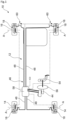
- FIG. 1 is a top view which schematically represents a braking system produced according to the teachings of the invention embedded in a four-wheeled motor vehicle.
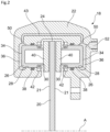
- FIG 2 is an axial half-section view, along the axis of rotation of a wheel, of a fixed-caliper disc brake fitted to a wheel of the vehicle of the figure 1 .
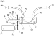
- FIG 3 is an axial sectional view, along the sliding axis of the parking piston, which represents a parking brake device which belongs to the braking system of the figure 1 and which is associated with the disc brake of the figure 2 , a parking piston of the parking brake device occupying a service position.
- FIG 4 is a view similar to that of the figure 3 in which the parking piston occupies a parking position.
- upstream will be used to designate a part of the hydraulic circuit close to a pressure generating element, such as a master cylinder, while the term downstream will be used to designate a part of the hydraulic circuit close to the caliper chambers.
- the motor vehicle 10 comprises two front wheels 14 and two rear wheels 16. Each wheel 14, 16 is rotatably mounted about an associated axis “A”.
- the braking system 12 comprises at least one disc brake 18 associated with a wheel 14, 16.
- the braking system 12 preferably comprises at least two disc brakes 18 each associated with a rear wheel 16.
- each wheel 14, 16 is equipped with an associated disc brake 18.
- each disc brake 10 comprises a disc 20 mounted integral in rotation with the associated wheel 14, 16 around its axis “A”.
- the disc 20 thus extends orthogonally to the axis “A”.
- the disc 20 and the wheel 14, 16 are thus coaxial with axis “A”.
- the disc 20 is delimited axially by two opposite faces. It is delimited radially by a circular peripheral edge 24.
- Each disc brake 10 further comprises at least one caliper 22 which overlaps the peripheral edge 24 of the disc 20.
- At least one caliper piston 26 is mounted to slide axially in an associated caliper cylinder 28.
- the caliper piston 26 is mounted to slide between a rest position and a braking position in which it is close to the disc 20 relative to its rest position.
- the caliper piston 26 has an external face 30 facing a face 21 of the disc 20 and an opposite internal face 34 which delimits with the caliper cylinder 28 a hydraulic chamber 36 of the caliper 22, called caliper chamber 36.
- An annular seal 38 is interposed between a cylindrical wall of the caliper piston 26 and a complementary cylindrical wall of the caliper cylinder 28 to ensure the sealing of the caliper chamber 36.
- Each disc brake 18 further comprises two brake pads 40 which are arranged axially facing each other on either side of the disc 20.
- the brake pads 40 are mounted to slide axially relative to the disc 20 between an inactive position in which they are spaced apart from the faces 22 of the disc 20 and an active braking position in which they are clamped against the faces 21 to grip the disc 20.
- One of the brake pads 40 is interposed between the outer face 30 of the caliper piston 26 and the disc 20.
- This brake pad 40 is mounted to slide axially in the caliper 22.
- the brake pad 40 is guided by the caliper 22.
- the brake pad 40 is advantageously made axially integral with the piston 26 by any known means.
- the brake pad 40 is mounted to slide freely relative to the caliper piston 26 so that the caliper piston 26 only controls the sliding of the brake pad 40 toward its active position, the brake pad 40 being returned elastically by an elastic return member (not shown) towards its inactive position.
- the clamping of the brake pad 40 against the disc 20 is controlled by pressurizing a brake fluid in the caliper chamber 36 which causes the caliper piston 26 to slide into a braking position towards the disc 20.
- the caliper piston 26 is elastically returned to a rest position by an elastic member, which is here formed by the annular seal 38.
- a bellows 42 is arranged to prevent particles from entering the caliper cylinder 28.
- this is a disc brake 18 with a fixed caliper 22. Since this is a caliper 22 fixed relative to the disc 20, the disc brake 18 comprises at least two caliper pistons 26 arranged on either side of the disc 20 to clamp the two brake pads 40.
- the structure and operation of the control members of the second caliper piston 26 are identical to what was described previously by symmetry relative to the plane of the disc 20.
- the second caliper piston 26 is in particular controlled in sliding by the pressure of a brake fluid in a second caliper chamber 36.
- the disc brake 18 thus comprises two caliper chambers 36 arranged on either side of the disc 20.
- the two caliper chambers 36 communicate here via a pipe 43 so that the brake fluid simultaneously and permanently has the same pressure in the two caliper chambers 36.
- At least some wheels are equipped with a floating caliper disc brake.
- a floating caliper disc brake In such a disc brake, only one side of the caliper is equipped with a piston that pushes the first brake shoe.
- the caliper is mounted to slide axially and the second brake shoe arranged opposite the piston relative to the disc is intended to be clamped against the disc by sliding the caliper after the piston has clamped the first brake shoe against the disc.
- the braking system 12 comprises a master cylinder 44 which is connected to each caliper chamber 36 of each disc brake 18 via a hydraulic circuit 46.
- the hydraulic circuit 46 branches into several branches 48, each of which is connected to an associated disc brake 18.
- each disc brake 18 is connected to the master cylinder 44 by a separate branch of the hydraulic circuit 46.
- two branches 48 are connected to each of the disc brakes 18 associated with the rear wheels 16 and two branches 48 are connected to each of the disc brakes 18 associated with the front wheels 14.
- Each branch 48 is more particularly connected to each caliper chamber 36 of the associated disc brake 18 via an inlet orifice 50 of each caliper chamber 36.
- the two caliper chambers 36 are both connected to the branch 48 of the hydraulic circuit 44 of the braking system 12 via a common supply port 52 which is here arranged in the caliper 22.
- the brake fluid pressure in the caliper chambers 36 is controlled by the driver by means of a brake pedal 54 which controls the master cylinder 44.
- a brake booster 56 is interposed between the pedal 54 and the master cylinder 44 to assist the driver.
- the pressure of the brake fluid in the caliper chambers 36 can also be controlled by an automatic driving assistance device 58, such as an “ESP” device.
- an assistance device 58 comprises a member which makes it possible to act on the pressure of the brake fluid independently of the master cylinder 44.
- This is generally a pump which is interposed in the hydraulic circuit 46 between the master cylinder 44 and the branches 48. The pump makes it possible in particular to vary the quantity of liquid present in the hydraulic circuit in order to vary the pressure of the brake fluid in the caliper chambers 36.
- the invention proposes to use the braking system 12 in a “parking brake” mode in order to actuate the disc brakes 18 for a prolonged period, in particular when the vehicle is parked with the engine off.
- the braking system 12 comprises at least one parking brake device 60.
- the parking brake device 60 is interposed in the hydraulic circuit 46 between the master cylinder 44 and the at least one caliper chamber 36 of the associated disc brake 18.
- each parking brake device 60 is interposed between the assistance device 58 and the at least one caliper chamber 36.
- the parking brake device 60 is capable of pressurizing the caliper chamber 36 independently of the master cylinder 44 to clamp the brake pad 40 against the disc 20.
- the parking brake device 60 is here interposed in the branch 48 which supplies the associated disc brake 18. Each parking brake device 60 is thus associated only with the disc brake 18 supplied by said branch 48.
- the braking system 12 comprises two identical parking brake devices 60, each of which is associated with a rear wheel disc brake 16 and which are each interposed in an associated branch 48 to individually control each disc brake 18 associated with the rear wheels 16.
- each parking brake device 60 comprises a cylinder, hereinafter called the parking cylinder 62, in which a piston, hereinafter called the parking piston 64, is slidably mounted.
- the parking piston 64 divides the parking cylinder 62 in a sealed manner into two chambers 66, 68 by means of an annular seal 69 arranged around the parking piston 64.
- the working chamber 66 has a variable volume depending on the position of the parking piston 64.
- the parking cylinder 62 comprises a first orifice 70 for connection to the master cylinder 44, hereinafter referred to as the upstream orifice 70, and a second orifice 72 for connection to the at least one caliper chamber 36 of the associated disc brake 18, hereinafter referred to as the downstream orifice 72.
- the parking piston 64 is slidably mounted between a service position, illustrated in figure 3 , in which the master cylinder 44 communicates directly with each caliper chamber 36 of the associated disc brake 18 via the working chamber 66 as indicated by the arrow “F”, and a parking position, illustrated in figure 4 , in which the volume of the working chamber 66 is reduced to pressurize each caliper chamber 36 of the associated disc brake 18.
- the master cylinder 44 In the service position of the parking piston 64, the master cylinder 44 is capable of directly controlling the pressure in the caliper chambers 36 of the associated disc brake 18 via the working chamber 66. To do this, in this service position, the upstream orifice 70 and the downstream orifice 72 both open into the working chamber 66.
- the upstream port 70 and the downstream port 72 are arranged so that, when the parking piston 64 leaves its service position, the parking piston 64 cuts off the communication between the master cylinder 44 and the working chamber 66.
- the upstream orifice 70 is here arranged in a cylindrical wall of the parking cylinder 62, in the immediate vicinity of the parking piston 64 in its service position.
- the parking piston 64 has slid from its service position to an intermediate position, corresponding substantially to a stroke of the dimension of the upstream orifice 70, the upstream orifice 70 no longer opens into the working chamber 66, as shown in broken lines in FIG. figure 4 .
- the seal 69 of the parking piston 64 exceeds the upstream orifice 70, the upstream orifice 70 no longer communicates with the working chamber 66.
- the upstream orifice 70 opens into the compensation chamber 68, so that the pressure in the master cylinder 44 remains substantially lower than the pressure in the caliper chamber 36 when the parking piston 64 occupies its parking position.
- the brake fluid located in the part of the hydraulic circuit 46 located directly upstream of the parking brake device 60 decreases.
- This pressure reduction can be automatically compensated by a reserve of brake fluid contained for example by an expansion tank of the master cylinder 44 whose cap allows air to escape and ensures atmospheric pressure in the circuit 46 when it is not actuated by the service brake.
- a wall of the piston constantly closes the upstream orifice 70.
- This is, for example, a skirt of the parking piston 64.
- the movements of the parking piston 64 between its service position and its parking position are controlled by an electric motor 74.
- a shaft 75 of the electric motor 74 drives the parking piston 64 via an irreversible motion transmission device 76.
- irreversible means that the motion can only be transmitted from the motor shaft 75 to the parking piston 64 but not in the opposite direction.
- the transmission device 76 comprises, for example, a screw-nut device.
- the worm screw 78 is integral in translation with one of the electric motor 74 or the parking piston 64, while the nut 80 is integral in translation with the other of the electric motor 74 or the parking piston 64.
- the worm screw 78 is integral by sliding with the parking piston 64.
- the worm screw 78 belongs more particularly to a rod 82 for controlling the parking piston 64.
- the worm screw 78 extends along an axis “B” parallel to the sliding direction of the parking piston 64.
- the nut 80 is itself integral in translation with the electric motor 74.
- the nut 80 is rotatably mounted around the axis “B” so as to be screwed onto the worm screw 78.
- the nut 80 is here driven in rotation in both directions by the motor shaft 75 via a gear mechanism comprising for example a driving pinion 84 mounted integral in rotation with the motor shaft 75 which meshes with a toothed wheel 86 whose hub is formed by the nut 80.
- the irreversible transmission device is formed by a worm device cooperating with a rack.
- the rack is slidably secured to the parking piston while the worm is rotated by the electric motor.
- the irreversible transmission device is formed by a cam and roller device.
- the roller is integral in sliding with the parking piston, while the cam is driven in movement by the electric motor.
- the parking piston is either elastically returned to one of its two positions among the service position or the parking position, or the cam comprises a groove which makes it possible to control the movements of the roller in both directions.
- the parking piston 64 occupies its service position shown in figure 3 .
- the master cylinder 44 and the assistance device 58 are capable of directly controlling the disc brakes 18 by varying the brake fluid pressure in the caliper chambers 36 via the working chamber 66.
- the parking piston 64 is controlled to slide via the electric motor 74.
- the parking piston 64 When the parking piston 64 reaches its intermediate position, it interrupts the communication between the upstream part of the hydraulic circuit 46, comprising the master cylinder 44 and the device 58 assistance, and the downstream part of the hydraulic circuit 46, comprising the associated caliper chamber(s) 36.
- the working chamber 66 communicates only with the caliper chamber(s) 36 of the associated disc brake 18.
- the working chamber 66, the caliper chamber(s) 36 and the associated pipes have an enclosed space containing a determined quantity of brake fluid.
- the sliding of the parking piston 64 reduces the volume of the working chamber 66 and therefore the volume of said enclosed space while the quantity of brake fluid remains unchanged. It follows that the pressure of the brake fluid increases in said enclosed space and, consequently, in the caliper chamber(s) 36.
- This parking brake device 60 is particularly advantageous in association with disc brakes 18 with fixed caliper 22, as is the case here. Indeed, by directly controlling the pressure of the brake fluid, the sliding of the parking piston 64 of the parking brake device 60 makes it possible to jointly control the pressure in the two caliper chambers 36. Thus, the two caliper pistons 26 of the same disc brake 18 are controlled simultaneously by the same common parking brake device 60.
- this parking brake device 60 is also applicable to floating caliper disc brakes, as explained previously.
- each parking brake device 60 be arranged in proximity to the disc brake 18 which it controls, in particular to reduce energy losses, the invention still makes it possible to physically distance the parking brake device 60 from the disc brake 18 that it controls. This makes it possible in particular to provide a certain freedom of design despite the bulk of the numerous components that must be arranged near the wheels 14, 16 of the vehicle.
Landscapes
- Engineering & Computer Science (AREA)
- Transportation (AREA)
- Mechanical Engineering (AREA)
- Braking Arrangements (AREA)
Applications Claiming Priority (1)
| Application Number | Priority Date | Filing Date | Title |
|---|---|---|---|
| FR2304998A FR3149063B1 (fr) | 2023-05-22 | 2023-05-22 | Systeme de freinage hydraulique comportant un dispositif de frein de parking |
Publications (1)
| Publication Number | Publication Date |
|---|---|
| EP4467404A1 true EP4467404A1 (de) | 2024-11-27 |
Family
ID=87974420
Family Applications (1)
| Application Number | Title | Priority Date | Filing Date |
|---|---|---|---|
| EP24176426.5A Withdrawn EP4467404A1 (de) | 2023-05-22 | 2024-05-16 | Hydraulische bremsanlage mit feststellbremseinrichtung |
Country Status (2)
| Country | Link |
|---|---|
| EP (1) | EP4467404A1 (de) |
| FR (1) | FR3149063B1 (de) |
Citations (3)
| Publication number | Priority date | Publication date | Assignee | Title |
|---|---|---|---|---|
| DE3518715A1 (de) * | 1985-05-24 | 1986-11-27 | Daimler-Benz Ag, 7000 Stuttgart | Feststell-bremseinrichtung |
| CN103332181A (zh) * | 2013-07-03 | 2013-10-02 | 李文明 | 一种自动驻车制动器 |
| EP3275741A1 (de) * | 2016-07-29 | 2018-01-31 | RENAULT s.a.s. | Verfahren zur steuerung des lösevorgangs eines bremssattels, und entsprechende vorrichtung |
-
2023
- 2023-05-22 FR FR2304998A patent/FR3149063B1/fr active Active
-
2024
- 2024-05-16 EP EP24176426.5A patent/EP4467404A1/de not_active Withdrawn
Patent Citations (3)
| Publication number | Priority date | Publication date | Assignee | Title |
|---|---|---|---|---|
| DE3518715A1 (de) * | 1985-05-24 | 1986-11-27 | Daimler-Benz Ag, 7000 Stuttgart | Feststell-bremseinrichtung |
| CN103332181A (zh) * | 2013-07-03 | 2013-10-02 | 李文明 | 一种自动驻车制动器 |
| EP3275741A1 (de) * | 2016-07-29 | 2018-01-31 | RENAULT s.a.s. | Verfahren zur steuerung des lösevorgangs eines bremssattels, und entsprechende vorrichtung |
Also Published As
| Publication number | Publication date |
|---|---|
| FR3149063A1 (fr) | 2024-11-29 |
| FR3149063B1 (fr) | 2025-04-18 |
Similar Documents
| Publication | Publication Date | Title |
|---|---|---|
| FR2689591A1 (fr) | Transmission avec organe d'enroulement. | |
| EP0912382B1 (de) | Bremskraftverstärker mit veränderbarer verstärkungsverhaltung | |
| FR2573711A1 (fr) | Systeme hydraulique de freinage avec regulation du glissement | |
| EP1352181A1 (de) | Elektromechanische betätigungseinrichtung einer mehrscheibenbremse für transportmittel, insbesondere für flugzeuge | |
| EP0659134B1 (de) | Pneumatischer kraftverstärker | |
| EP0005675B1 (de) | Radzylinder | |
| EP0340059A1 (de) | Bremskraftverstärker mit einstellbarem Schwellenwert | |
| FR3149063A1 (fr) | Systeme de freinage hydraulique comportant un dispositif de frein de parking | |
| EP0891908B1 (de) | Kraftfahrzeugbremsvorrichtung mit Feststellbremse | |
| FR2684059A1 (fr) | Servomoteur pneumatique. | |
| FR2539688A1 (fr) | Dispositif de regulation de pression pour frein de roue arriere de vehicule automobile | |
| FR3015406A1 (fr) | Frein a disque comportant un frein de stationnement a actionnement hydraulique | |
| FR2562855A1 (fr) | Systeme de freinage hydraulique | |
| EP0966620B1 (de) | Hybrides mehrscheibenbremssystem | |
| FR2666552A1 (fr) | Procede de reglage de la valeur du saut d'un servomoteur pneumatique d'assistance au freinage et servomoteur pour la mise en óoeuvre de ce procede. | |
| EP0368691B1 (de) | Steuervorrichtung eines Kraftverstärkers, insbesondere für Kraftfahrzeugbremsanlagen | |
| EP0999964B1 (de) | Pneumatischer kraftverstärker mit steuerkammer | |
| WO1999022976A1 (fr) | Maitre-cylindre a clapets a course morte reduite | |
| EP0041020B1 (de) | Druckdosiereinheit für eine Bedienungseinrichtung für Fahrzeugbremsen | |
| FR2954804A1 (fr) | Rondelle d'ejection, pompe a liquide equipee d'une telle rondelle pour un module hydraulique et module ainsi equipe | |
| EP0939715B1 (de) | Hilfskraftunterstütztes bremssystem mit verbesserter hydraulischer reaktion | |
| FR3132552A1 (fr) | Dispositif de serrage pour système de freinage comprenant un réservoir de graisse de lubrification | |
| EP0368701B1 (de) | Hydraulische Servobremsanlage und Bremskraftverstärker und Regelventil für eine solche Anlage | |
| EP3087288B1 (de) | Scheibenbremse mit hydraulischer steuerung mit einer feststellbremse mit hydraulischer betätigung | |
| EP1350702A1 (de) | Hauptbremszylinder mit reduzierter Geräuschentwicklung |
Legal Events
| Date | Code | Title | Description |
|---|---|---|---|
| PUAI | Public reference made under article 153(3) epc to a published international application that has entered the european phase |
Free format text: ORIGINAL CODE: 0009012 |
|
| STAA | Information on the status of an ep patent application or granted ep patent |
Free format text: STATUS: THE APPLICATION HAS BEEN PUBLISHED |
|
| AK | Designated contracting states |
Kind code of ref document: A1 Designated state(s): AL AT BE BG CH CY CZ DE DK EE ES FI FR GB GR HR HU IE IS IT LI LT LU LV MC ME MK MT NL NO PL PT RO RS SE SI SK SM TR |
|
| STAA | Information on the status of an ep patent application or granted ep patent |
Free format text: STATUS: REQUEST FOR EXAMINATION WAS MADE |
|
| 17P | Request for examination filed |
Effective date: 20250425 |
|
| STAA | Information on the status of an ep patent application or granted ep patent |
Free format text: STATUS: THE APPLICATION IS DEEMED TO BE WITHDRAWN |
|
| 18D | Application deemed to be withdrawn |
Effective date: 20250528 |