EP4467446A2 - Verbessertes oberflurverkabelung für ein flugzeugfrachthandhabungssystem - Google Patents
Verbessertes oberflurverkabelung für ein flugzeugfrachthandhabungssystem Download PDFInfo
- Publication number
- EP4467446A2 EP4467446A2 EP24173892.1A EP24173892A EP4467446A2 EP 4467446 A2 EP4467446 A2 EP 4467446A2 EP 24173892 A EP24173892 A EP 24173892A EP 4467446 A2 EP4467446 A2 EP 4467446A2
- Authority
- EP
- European Patent Office
- Prior art keywords
- coupled
- tray
- connector
- wire bundle
- various embodiments
- Prior art date
- Legal status (The legal status is an assumption and is not a legal conclusion. Google has not performed a legal analysis and makes no representation as to the accuracy of the status listed.)
- Pending
Links
Images




Classifications
-
- B—PERFORMING OPERATIONS; TRANSPORTING
- B64—AIRCRAFT; AVIATION; COSMONAUTICS
- B64D—EQUIPMENT FOR FITTING IN OR TO AIRCRAFT; FLIGHT SUITS; PARACHUTES; ARRANGEMENT OR MOUNTING OF POWER PLANTS OR PROPULSION TRANSMISSIONS IN AIRCRAFT
- B64D9/00—Equipment for handling freight; Equipment for facilitating passenger embarkation or the like
-
- B—PERFORMING OPERATIONS; TRANSPORTING
- B64—AIRCRAFT; AVIATION; COSMONAUTICS
- B64C—AEROPLANES; HELICOPTERS
- B64C1/00—Fuselages; Constructional features common to fuselages, wings, stabilising surfaces or the like
- B64C1/18—Floors
- B64C1/20—Floors specially adapted for freight
-
- H—ELECTRICITY
- H02—GENERATION; CONVERSION OR DISTRIBUTION OF ELECTRIC POWER
- H02G—INSTALLATION OF ELECTRIC CABLES OR LINES, OR OF COMBINED OPTICAL AND ELECTRIC CABLES OR LINES
- H02G3/00—Installations of electric cables or lines or protective tubing therefor in or on buildings, equivalent structures or vehicles
- H02G3/02—Details
- H02G3/04—Protective tubing or conduits, e.g. cable ladders or cable troughs
- H02G3/0437—Channels
-
- B—PERFORMING OPERATIONS; TRANSPORTING
- B64—AIRCRAFT; AVIATION; COSMONAUTICS
- B64D—EQUIPMENT FOR FITTING IN OR TO AIRCRAFT; FLIGHT SUITS; PARACHUTES; ARRANGEMENT OR MOUNTING OF POWER PLANTS OR PROPULSION TRANSMISSIONS IN AIRCRAFT
- B64D9/00—Equipment for handling freight; Equipment for facilitating passenger embarkation or the like
- B64D2009/006—Rollers or drives for pallets of freight containers, e.g. PDU
-
- B—PERFORMING OPERATIONS; TRANSPORTING
- B64—AIRCRAFT; AVIATION; COSMONAUTICS
- B64D—EQUIPMENT FOR FITTING IN OR TO AIRCRAFT; FLIGHT SUITS; PARACHUTES; ARRANGEMENT OR MOUNTING OF POWER PLANTS OR PROPULSION TRANSMISSIONS IN AIRCRAFT
- B64D2221/00—Electric power distribution systems onboard aircraft
-
- H—ELECTRICITY
- H01—ELECTRIC ELEMENTS
- H01R—ELECTRICALLY-CONDUCTIVE CONNECTIONS; STRUCTURAL ASSOCIATIONS OF A PLURALITY OF MUTUALLY-INSULATED ELECTRICAL CONNECTING ELEMENTS; COUPLING DEVICES; CURRENT COLLECTORS
- H01R13/00—Details of coupling devices of the kinds covered by groups H01R12/70 or H01R24/00 - H01R33/00
- H01R13/73—Means for mounting coupling parts to apparatus or structures, e.g. to a wall
-
- H—ELECTRICITY
- H01—ELECTRIC ELEMENTS
- H01R—ELECTRICALLY-CONDUCTIVE CONNECTIONS; STRUCTURAL ASSOCIATIONS OF A PLURALITY OF MUTUALLY-INSULATED ELECTRICAL CONNECTING ELEMENTS; COUPLING DEVICES; CURRENT COLLECTORS
- H01R2201/00—Connectors or connections adapted for particular applications
- H01R2201/26—Connectors or connections adapted for particular applications for vehicles
-
- H—ELECTRICITY
- H02—GENERATION; CONVERSION OR DISTRIBUTION OF ELECTRIC POWER
- H02G—INSTALLATION OF ELECTRIC CABLES OR LINES, OR OF COMBINED OPTICAL AND ELECTRIC CABLES OR LINES
- H02G3/00—Installations of electric cables or lines or protective tubing therefor in or on buildings, equivalent structures or vehicles
- H02G3/30—Installations of cables or lines on walls, floors or ceilings
- H02G3/32—Installations of cables or lines on walls, floors or ceilings using mounting clamps
Definitions
- the present disclosure generally relates generally to cargo handling system, and more particularly, to above floor wire routing for aircraft cargo handling systems.
- Aircraft cargo handling systems move cargo in the aircraft using powered rollers called Power Drive Units (PDU).
- PDU Power Drive Units
- the PDUs are connected to aircraft power and their control system through several wire harnesses.
- these wire harnesses are located under the floor of the cargo hold and pass through holes in the floor and/or supporting structure of the cargo hold to connect to the PDUs.
- cargo handling systems may include other powered line replaceable units (LRUs), such as sensors, that use power routed beneath the cargo hold. Routing cables under the cargo hold adds complexity to installation and maintenance operations due to having to access the area beneath the cargo hold, and sometimes behind the cargo hold walls.
- LRUs powered line replaceable units
- the above floor wiring system includes a tray including a sidewall, a wire bundle secured to the sidewall, and a junction card coupled to the sidewall and electrically coupled to the wire bundle.
- the above floor wiring system further includes a connector coupled to the wire bundle, the connector disposed at a first side of the tray, and a ground wire coupled to the connector and to the tray.
- the above floor wiring system further includes a post coupled to the junction card and the tray, the post securing the junction card to the tray and electrically grounding the junction card.
- the above floor wiring system further includes a hole formed through the sidewall of the tray and a surface mount connector coupled to the junction card and extending through the hole. In various embodiments, the above floor wiring system further includes a slot formed in the sidewall and a pigtail connector coupled to the junction card and extending through the slot. In various embodiments, the above floor wiring system further includes a support bracket coupled to the sidewall and extending over the slot.
- the above floor wiring system further includes a housing formed over the junction card and a clamp securing the wire bundle to the tray.
- the cargo handling system includes a floor including an upper surface, a first tray coupled to the upper surface of the floor, the first tray extending in a first direction, a first wire bundle coupled to the first tray, and a first junction card coupled to the first tray and coupled to the first wire bundle.
- the cargo handling system further includes a second tray coupled to the upper surface of the floor, the second tray disposed adjacent the first tray and extending in a second direction orthogonal to the first direction, a second wire bundle having a first end and a second end, the first end of the second wire bundle coupled to the first junction card, and a second junction card coupled to the second tray and the second end of the second wire bundle.
- the cargo handling system further includes a wall extending from the upper surface of the floor, wherein the first wire bundle is further coupled directly to the wall, and a third junction card coupled to the wall and coupled to the first wire bundle.
- the cargo handling system further includes a line replaceable unit connector coupled to the wall and a third wire bundle coupled to the third junction card at a first end and coupled to the line replaceable unit connector at a second end.
- the cargo handling system further includes a unit load device disposed on the upper surface of the floor and a fourth wire bundle having a first end and a second end, the first end of the fourth wire bundle coupled to the unit load device and the second end of the fourth wire bundle coupled to the line replaceable unit connector.
- the cargo handling system further includes a connector coupled to the first wire bundle, a power source coupled to the connector, and a ground wire coupled to the connector and to the first tray.
- the cargo handling system further includes a post coupled to the first junction card and the first tray, the post securing the first junction card to the first tray and electrically grounding the first junction card.
- the cargo handling system includes a floor having an upper surface, a first tray coupled to the upper surface of the floor, a second tray coupled to the upper surface of the floor, the second tray disposed adjacent the first tray, a first wire bundle having a first end and a second end, a first connector coupled to the first end of the first wire bundle, a first junction card coupled to the second end of the first wire bundle and to the first tray, a second wire bundle having a first end and a second end, a second junction card coupled to the first end of the second wire bundle and to the second tray, and a second connector coupled to the second end of the second wire bundle, wherein the second connector is coupled to the first connector.
- the cargo handling system further includes a power source and a third wire bundle having a first end and a second end, the first end of the third wire bundle coupled to the power source and the second end of the third wire bundle coupled to the first junction card.
- the cargo handling system further includes an opening formed through the first tray and a surface mount connector coupled to the first junction card, the surface mount connector extending through the opening in the first tray.
- the cargo handling system further includes a slot formed in the second tray and a pigtail connector coupled to the second junction card, the pigtail connector extending through the slot in the second tray.
- the cargo handling system further includes a third wire bundle having a first end and a second end, the first end of the third wire bundle coupled to the first junction card and a line replaceable unit connector coupled to the second end of the third wire bundle.
- the cargo handling system further includes a first ground wire coupled to the first connector and to the first tray and a second ground wire coupled to the second connector and to the second tray.
- wire bundles used with aircraft cargo handling systems include many individual wires that are routed to the various line replaceable units (LRUs) in the cargo handling system.
- LRUs line replaceable units
- the LRUs are installed in trays in the cargo handling systems and the wires in the wire bundle connect to the LRU.
- the diameter of the wire bundle increases as the number of wires included increases. This results in the use of larger connectors to splice wires and LRUs into the cargo handling system.
- Typical systems include passing the entire wire bundle through an opening in the tray, connect to the LRU, or other component, and pass the entire wire bundle back through the opening in the tray. This is cumbersome and inefficient. Similarly, there are difficulties within typical cargo handling systems of routing wires between multiple trays, LRUs, and/or unit load devices (ULDs).
- the wire routing system includes a junction card that is spliced into the wire bundle providing a space efficient junction for connections to an LRU.
- the junction card is coupled to the tray using one or more posts.
- a molded cover houses the junction card and posts, providing protection from the elements and cargo.
- the wire bundle includes a connector at each end of the tray. In various embodiments, each connector is electrically ground to the tray by one or more ground wires.
- a connector may be coupled to the junction card to provide power and/or data to the LRU.
- multiple connectors may be spliced into a single wire bundle with little to no effect on the size or safety of the wire bundle.
- the junction card may be used for addressing the LRU coupled to the junction card.
- the wire bundle may be armored using a flexible, protected cable.
- the flexible, protected cable may be coupled to a sidewall of the cargo handling system and/or the aircraft to provide additional power and/or data connections.
- Aircraft 10 may comprise a cargo load door 16 located, for example, at one side of a fuselage structure of aircraft 10.
- a unit load device (ULD) 20 in the form of a container or pallet, for example, may be loaded through cargo load door 16 and onto cargo deck 12 of aircraft 10 or, conversely, unloaded from cargo deck 12 of aircraft 10.
- ULDs are available in various sizes and capacities, and are typically standardized in dimension and shape. Once loaded with items destined for shipment, ULD 20 is transferred to aircraft 10 and then loaded onto aircraft 10 through cargo load door 16 using a conveyor ramp, scissor lift or the like.
- ULD 20 is moved within cargo compartment 14 to a final stowed position.
- Multiple ULDs may be brought on-board aircraft 10, with each ULD 20 being placed in a respective stowed position on cargo deck 12.
- each ULD 20 is unloaded from aircraft 10 in similar fashion, but in reverse sequence to the loading procedure.
- aircraft 10 may include a cargo handling system as described herein in accordance with various embodiments.
- Cargo handling system 100 is illustrated with reference to an XYZ coordinate system, with the X-direction extending longitudinally aft and the Z-direction extending vertically with respect to an aircraft in which cargo handling system 100 is positioned, such as, for example, aircraft 10 described above with reference to FIG. 1A .
- cargo handling system 100 may define a conveyance surface 102 having a plurality of trays 104 supported by a cargo deck 112, such as, for example, cargo deck 12 described above with reference to FIG. 1A .
- Plurality of trays 104 may be configured to support a unit load device (ULD) 120 (or a plurality of ULDs), such as, for example, unit load device (ULD) 20 described above with reference to FIG. 1A .
- ULD 120 may comprise a container or a pallet configured to hold cargo as described above.
- plurality of trays 104 is disposed throughout cargo deck 112 and may support a plurality of conveyance rollers 106, where one or more or all of plurality of conveyance rollers 106 is a passive roller.
- plurality of trays 104 may further support a plurality of power drive units (PDUs) 110, each of which may include one or more drive rollers 108 that may be actively powered by a motor.
- PDUs power drive units
- one or more of plurality of trays 104 is positioned longitudinally along cargo deck 112 - e.g., along the X-direction extending from the forward end to the aft end of aircraft 10.
- plurality of conveyance rollers 106 and one or more drive rollers 108 may be configured to facilitate transport of ULD 120 in the forward and the aft directions along conveyance surface 102.
- ULD 120 may variously contact the one or more drive rollers 108 to provide a motive force for transporting ULD 120 along conveyance surface 102.
- Each of the plurality of PDUs 110 may include an actuator, such as, for example, an electrically operated motor, configured to drive the one or more drive rollers 108 corresponding with each such PDU 110.
- the one or more drive rollers 108 may be raised from a lowered position beneath conveyance surface 102 to an elevated position above conveyance surface 102 by the corresponding PDU 110.
- the term "beneath" may refer to the negative Z-direction
- the term “above” may refer to the positive Z-direction with respect to conveyance surface 102.
- PDUs 110 may include a drive roller that is held or biased in a position above conveyance surface 102 by a spring.
- PDUs 110 as disclosed herein may be any type of electrically powered rollers that may be selectively energized to propel or drive ULD 120 in a desired direction over cargo deck 112 of aircraft 10.
- the plurality of trays 104 may further support a plurality of restraint devices 114. In various embodiments, each of the plurality of restraint devices 114 may be configured to rotate downward as ULD 120 passes over and along conveyance surface 102.
- the plurality of trays 104 may further support one or more sensors, restraints, or other line replaceable units (LRUs).
- LRUs line replaceable units
- cargo handling system 100 may include a system controller 130 in communication with each of the plurality of PDUs 110 via a plurality of channels 132.
- Each of the plurality of channels 132 may be a data bus, such as, for example, a controller area network (CAN) bus.
- An operator may selectively control operation of the plurality of PDUs 110 using system controller 130.
- system controller 130 may be configured to selectively activate or deactivate the plurality of PDUs 110.
- cargo handling system 100 may receive operator input through system controller 130 to control the plurality of PDUs 110 in order to manipulate movement of ULD 120 over conveyance surface 102 and into a desired position on cargo deck 112.
- system controller 130 may include a general purpose processor, a digital signal processor (DSP), an application specific integrated circuit (ASIC), a field programmable gate array (FPGA) or some other programmable logic device, discrete gate or transistor logic, discrete hardware components, or any combination thereof.
- Cargo handling system 100 may also include a power source 126 configured to supply power to the plurality of PDUs 110 or to the plurality of restraint devices 114 via one or more power buses 128.
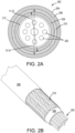
- Electrical harness 200 may include an electrical cable 212 comprising a plurality of wires 202 disposed within an armored electrical harness 204 comprising an outer tubing 206, an inner tubing 208, and a braid tubing 210 disposed between inner tubing 208 and outer tubing 206.
- outer tubing 206 and inner tubing 208 are made from a polymeric material, including thermosetting and/or thermoplastic polymers, such as a polyurethane, among others.
- braid tubing 210 comprises a wire braided tube or sleeve made from a metallic material, such as stainless steel, among others. In various embodiments, braid tubing 210 comprises a wire braided tube or sleeve made from metal-coated fibers. In various embodiments, braid tubing 210 comprises a braided tube or sleeve made from a non-metallic material. With momentary reference to FIG. 2B , braid tubing 210 includes wires tightly braided together to form a generally cylindrical tubing. Furthermore, inner tubing 208 and outer tubing 206 generally conform to the cylindrical shape of braid tubing 210. With respect to FIG. 2B , elements with like element numbering, as depicted in FIG. 2A , are intended to be the same and will not necessarily be repeated for the sake of clarity.
- inner tubing 208 may be disposed about electrical cable 212.
- Inner tubing 208 may encase electrical cable 212.
- inner tubing 208 encases a plurality of wires 202 of electrical cable 212.
- Inner tubing 208 may be formed over the plurality of wires 202 via a polymer extrusion manufacturing process in which a polymer is melted and formed in a continuous profile along the length of electrical harness 200.
- Braid tubing 210 may be disposed about inner tubing 208.
- Braid tubing 210 may encase inner tubing 208.
- Inner diameter D1 of braid tubing 210 may be substantially equal to outer diameter D2 of inner tubing 208.
- the inner diameter surface of braid tubing 210 may be in contact with the outer diameter surface of inner tubing 208.
- Outer tubing 206 may be disposed about braid tubing 210.
- Outer tubing 206 may encase braid tubing 210.
- Outer tubing 206 may be formed over braid tubing 210 via a polymer extrusion manufacturing process in which a polymer is melted and formed in a continuous profile along the length of electrical harness 200.
- Outer diameter D3 of braid tubing 210 may be substantially equal to inner diameter D4 of outer tubing 206.
- the outer diameter surface of braid tubing 210 may be in contact with the inner diameter surface of outer tubing 206.
- braid tubing 210 is compressed between outer tubing 206 and inner tubing 208. Due to the relatively soft, elastic nature of outer tubing 206 and inner tubing 208, braid tubing 210 may embed into outer tubing 206 and inner tubing 208, thereby mechanically locking with outer tubing 206 and inner tubing 208 which prevents braid tubing 210 from slipping against outer tubing 206 and inner tubing 208. Thus, braid tubing 210 is in physical contact with outer tubing 206 and inner tubing 208. In this manner, outer tubing 206 and inner tubing 208 compresses braid tubing 210 such that braid tubing 210 maintains a common diameter along the length of electrical harness 200.
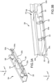
- tray 304 may be one of the plurality of trays 104 described above in FIG. 1B .
- Tray 304 includes a sidewall 304a, a top portion 304b, and a bottom portion 304c.
- Tray 304 further supports one or more rollers 306, a power drive unit (PDU) 310, a cable 320, clamps 322, and an electric connector 324.
- PDU 310 may be an example of PDU 110 and rollers 306 may be examples of conveyance rollers 106 described above in FIG. 2B .
- cable 320 may be an example of electrical harness 200 described above in FIGS. 2A and 2B .
- tray 304 may further support one or more sensors.
- cable 320 may be coupled to sidewall 304a by one or more clamps 322. In various embodiments cable 320 may run the length of tray 304 (e.g., parallel to the x-axis).
- electric connector 324 may be spliced into cable 320 to provide power to PDU 310. Splicing electric connector 324 into cable 320 may include separating cable 320 into a first portion 320a and a second portion 320b. Electric connector 324 may then be coupled to each portion of cable 320 such that first portion 320a is electrically coupled a first side of electric connector 324 and second portion 320b is electrically coupled to a second side of electric connector 324.
- a hole may be formed through sidewall 304a through which electric connector 324 passes to connect to PDU 310.
- a slot 326 may be cut through tray 304, and more specifically, through top portion 304b and sidewall 304a through which electric connector 324 passes to connect to PDU 310.
- one or more holes and/or slots 326 may be formed in tray 304 to power multiple line replaceable units (LRUs).
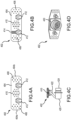
- junction card 402 for use with tray 304 is illustrated, in accordance with various embodiments.
- junction card 402 may be an example of electric connector 324 described above in FIGS. 3A and 3B .
- Junction card 402 may be spliced into a power cable used with tray 304.
- junction card 402 may be a printed circuit assembly (PCA) that passes power and/or signals from a first end to a second end, including one or more connections between the first end and the second end.
- Junction card 402 includes a board 404, a first plurality of pads 406, a second plurality of pads 408, a third plurality of pads 410, and one or more posts 412.
- Board 404 includes a first end 404a and a second end 404b.
- board 404 may be a printed circuit board (PCB) configured to connect electric and/or electronic components to one another.
- PCB printed circuit board
- board 404 may be single sided (e.g., a single conductive layer), double sided (e.g., two conductive layers), or multi-layer (e.g., alternating conductive layers).
- the first plurality of pads 406 is configured to be electrically coupled to a first cable (e.g., first portion 320a of cable 320) and the second plurality of pads 408 is configured to be electrically coupled to a second cable (e.g., second portion 320b of cable 320).
- the third plurality of pads 410 is configured to be electrically coupled to an LRU (e.g., PDU 310).
- the plurality of pads 406, 408, 410 in various embodiments, may be through-holes formed through board 404. In various embodiments, the plurality of pads 406, 408, 410 may be surface pads formed on board 404. In various embodiment, the plurality of pads 406, 408, 410 may be a combination of through-hole and surface pad.
- the first cable and/or the second cable may be soldered to junction card 402. In various embodiments, the first cable and/or the second cable may be coupled to junction card 402 by wire wrapping, using a terminal block, or other methods.
- the one or more posts 412 are configured to secure junction card 402 to tray 304.
- the one or more posts 412 may be a bolt that passes through sidewall 304a of tray 304 and is secured by a nut on each side.
- the one or more posts 412 may be used as a ground connector for the first cable and the second cable, as will be discussed in further detail below.
- junction card 402 may further includes a plurality of selectors 414.
- the plurality of selectors 414 may be used to select an address for the LRU connected to junction card 402, such as in a pin selection.
- the plurality of selectors 414 may be a plurality of resistors having low electrical resistance that are soldered to board 404.
- One or more of the plurality of resistors i.e., selectors 414) may be added or removed to identify the address of the LRU.
- the plurality of selectors 414 may be a plurality of jumper pins soldered to board 404.
- One or more connectors may be placed on or removed from one or more pairs of jumper pins (i.e., selectors 414) to identify the address of the LRU.
- the plurality of selectors 414 may be a plurality of dip switches coupled to board 404.
- One or more of the plurality of dip switches (i.e., selectors 414) may be toggled to identify the address of the LRU.
- Pigtail connector 420 coupled to junction card 402 is illustrated, in accordance with various embodiments.
- Pigtail connector 420 includes a tail 422 and a connector 424.
- a first end of tail 422 is coupled to board 404, and more specifically, to the third plurality of pads 410.
- a second end of tail 422 is coupled to connector 424.
- Connector 424 may be any suitable connector that is configured to connect to an LRU (e.g., PDU 310).
- tail 422 may fit through a hole in sidewall 304a of tray 304.
- tail 422 may be inserted into slot 326 of tray 304.
- a surface mount connector 430 coupled to junction card 402 is illustrated, in accordance with various embodiments.
- Surface mount connector 430 is coupled to the third plurality of pads 410 on board 404.
- Surface mount connector 430 may be any suitable connector that is configured to connect to an LRU (e.g., PDU 310).
- LRU e.g., PDU 310
- surface mount connector 430 is small enough to pass through a hole in sidewall 304a of tray 304.
- surface mount connector 430 may pass through slot 326 in tray 304.
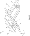
- FIGS. 5A-5D views of electric connectors are illustrated, in accordance with various embodiments.
- FIG. 5A illustrates a perspective view of the connector side of a wire routing system 500.
- FIGS. 5B and 5C illustrate perspective views of a wire routing system 520.
- FIG. 5D illustrates a perspective view of a wire routing system 550.
- the wire routing systems 500, 520, 550 illustrated and described herein are for description and understanding and are not intended to be limiting.
- Wire routing system 500 illustrated in FIG. 5A , includes an electric connector coupled to a tray 304.
- tray 304 includes sidewall 304a, top portion 304b, and bottom portion 304c.
- the electric connector includes posts 412 and surface mount connector 430, each of which extends through sidewall 304a of tray 304.
- Surface mount connector 430 is illustrated having a circular cross section.
- surface mount connector 430 may have a rectangular, square, D-shape cross section, among others.
- a size of the hole in sidewall 304a may vary based on a size of surface mount connector 430.
- the size of the hole has an upper size threshold, above which the strength of tray 304 may be compromised. Therefore, surface mount connector 430 has a relatively significant size without compromising the strength of tray 304.
- Wire routing system 520 illustrated in FIGS. 5B and 5C , includes a pigtail connector 420, an electric connector 324, a tray 304, a first cable 522, a second cable 524, a third cable 526, and a support bracket 528.
- Tray 304 includes a sidewall 304a, a top portion 304b, and a bottom portion 304c.
- a slot 326 is formed through top portion 304b and sidewall 304a.
- Electric connector 324 includes a junction card such as junction card 402 described above in FIGS. 4A-4D . First cable 522 and second cable 524 are spliced together using the junction card in electric connector 324.
- Third cable 536 is electrically coupled to the junction card and extends through slot 326 and is connected to pigtail connector 420.
- a hole that is larger than the upper size threshold may comprise the strength of tray 304.
- a size of slot 326 may be larger the upper threshold. Accordingly, support bracket 528 is coupled to tray 304, over slot 326, to provide structural support through tray 304.
- Wire routing system 550 includes a first tray 552, a second tray 554, a first cable 556, a second cable 558, a first pigtail connector 560, a second pigtail connector 562, a first electric connector 564, and a second electric connector 566.
- first tray 552 and second tray 554 may be examples of tray 304 described above in FIGS. 3A and 3B .
- first cable 556 and second cable 558 may be examples of electrical harness 200 described above in FIGS. 2A and 2B .
- first pigtail connector 560 and second pigtail connector 562 may be examples of pigtail connector 420.
- first electric connector 564 and second electric connector 566 may be examples of electric connector 324 including a junction card 402.
- First tray 552 extends in a first direction (e.g., parallel to the x-axis) and second tray 554 extends in a second direction (e.g., parallel to the y-axis) that is perpendicular to the first direction. That is, first tray 552 and second tray 554 form a T-junction over which power is shared.
- second tray 554 may be coupled to first tray 552. In various embodiments, second tray 554 may not physically contact first tray 552.
- First cable 556 extends along first tray 552 and second cable 558 extends along second tray 554.
- First cable 556 includes two splices, first electric connector 564 and second electric connector 566.
- First electric connector 564 is connected to first pigtail connector 560 that extends through a slot 570 in first tray 552.
- a support bracket 568 may be coupled to first tray 552 to provide structural support adjacent slot 570.
- Second electric connector 568 is connected to second pigtail connector 562 by second cable 558. As illustrated, second cable 558 does not extend through either first tray 552 or second tray 554.
- first electric connector 564 and second electric connector 566 each including a junction card, provide an efficient, secure, and space saving package for connecting various line replaceable units (LRUs) (e.g., power drive unit (PDU)) that may be disposed in either first tray 552 and/or second tray 554.
- LRUs line replaceable units
- PDU power drive unit
- Wire routing system 600 includes a tray 304, a cable 320, a junction card 402, a pigtail connector 420, a first end connector 602, a second end connector 604, a first ground wire 606, and a second ground wire 608.
- FIG. 6A is a first end of tray 304
- FIG. 6B is a middle portion of tray 304
- FIG. 6C is a second end of tray 304.
- First end connector 602 and second end connector 604 are positioned and configured to couple with a corresponding connector on an adjacent tray.
- a first end of first ground wire 606 is coupled to first end connector 602 and a second end of first ground wire 606 is coupled to tray 304.
- a first end of second ground wire 608 is coupled to second end connector 604 and a second end of second ground wire 608 is coupled to tray 304.
- tray 304 becomes a ground plane for cable 320. This reduces a size and weight of cable 320 by removing the ground wires from cable 320. Furthermore, this reduces a resistance of the ground plane by grounding cable 320 and connectors to the cargo handling system (e.g., cargo handling system 100) and/or the aircraft (e.g., aircraft 10).
- Junction card 402 is spliced into cable 320, as previously described above. That is, cable 320 is electrically connected (e.g., soldered) to junction card 402. Junction card 402 is secured to tray 304 by posts 412. Posts 412 further serve as a ground connection for pigtail connector 420 because posts 412 are electrically grounded to tray 304. Therefore, posts 412 provide a path to ground for pigtail connector 420 which.
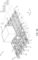
- Cargo handling system 700 includes trays 304, a first power source 702, a second power source 704, cables 706, 708, 710, 712, 714, 716, 718, 720, 722, 724, 726, 728, 730, electric connectors 732, cargo 734, and line replaceable unit (LRU) connectors 736.
- Trays 304 extend longitudinally (e.g., along the x-axis) within cargo handling system 700.
- trays 304 may include one or more power drive units (e.g., PDU 310).
- LRUs connected to LRU connectors 736 may include maintenance displays, system controllers, wireless access points, various sensor types, cameras, emergency stops, or docking station for controllers/maintenance unit (with wired or wireless charging and data transfer), among others. It should be appreciated, that the locations of the various cables, connectors, power sources, and trays described herein are for illustrated for discussion purposes and are not intended to be limiting as to quantity or location.
- Cable 706 may be coupled to first power source 702 and cable 708 may be coupled to second power source 704.
- first power source 702 and second power source 704 may be connected to an aircraft (e.g., aircraft 10) power source (e.g., an auxiliary power unit (APU)).
- APU auxiliary power unit
- cable 706 and cable 708 extend longitudinally (e.g., along the x-axis) within cargo handling system 700.
- Cable 710 extends axially (e.g., along the y-axis) and is coupled to cable 706 and cable 708.
- Cable 712 and cable 714 extend axially (e.g., in the positive y-direction) from cable 708 and are both coupled to cable 708.
- An electric connector 732 is located at each connection between cables.
- electric connector 732 may be an example of electric connector 324 including junction card 402 as described in FIGS. 3A, 3B , and 4A-4D .
- LRU connectors 736 provide electrical and/or data access to LRUs within cargo handling system 700, such as for example, power drive units, sensors, cameras, or the like.
- LRU connectors 736 may provide power to cargo 724, such as a unit load devices (ULD) or other cargo.
- the ULDs may include GPS/smart enabled containers, refrigerated containers, modular crew rests, or seating pods in a flexible cargo system, among others.
- Cables 720 and 731 provide a connection between cargo 734 (e.g., ULD) and LRU connectors 736.
- LRU connectors 736 may further include controllers for controlling cargo handling system 700.
- Cables 716, 718, 726, 728, and 730 are coupled to a wall 740 of cargo handling system 700 (e.g., interior wall of aircraft 10).
- p-clamps may be used to couple cables 716, 718, 726, 728, 730 to wall 740.
- other connectors may be used to couple cables 716, 718, 726, 728, 730 to wall 740, such as for example, rivet nuts. It should be understood that each cable 706, 708, 710, 712, 714, 716, 718, 720, 722, 724, 726, 728, 730 provides a connection from power source 702, 704 to an LRU or an LRU connector 736.
- cables 716, 718, 726, 728, 730 may be affixed, attached, coupled, mounted, or otherwise connected to any location along wall 740 including edges of wall panels, the center of wall panel, or other portions of wall 740 without removing any portion of wall 740 and without restriction as to where cables are 716, 718, 726, 728, 730 placed.
- routing cables and cable management includes removing walls 740 of cargo handling system 700 or aircraft 10 in order to place the cables behind the walls.
- the aircraft e.g., aircraft 10) may need to be recertified for flight after removing the walls.
- metal conduit has been used to connect power and/or data cables to the walls of aircraft 10.
- an aircraft e.g., aircraft 10
- cargo handling system 700 may be rewired using above floor wire routing that reduces the time and expense related to labor, recertifications, and planning around other subsystems. This an improved system for cargo handling installations and retrofits.
Landscapes
- Engineering & Computer Science (AREA)
- Aviation & Aerospace Engineering (AREA)
- Architecture (AREA)
- Civil Engineering (AREA)
- Structural Engineering (AREA)
- Mechanical Engineering (AREA)
- Connector Housings Or Holding Contact Members (AREA)
- Body Structure For Vehicles (AREA)
- Installation Of Indoor Wiring (AREA)
Applications Claiming Priority (1)
| Application Number | Priority Date | Filing Date | Title |
|---|---|---|---|
| US18/310,692 US12497170B2 (en) | 2023-05-02 | 2023-05-02 | Above-floor wire routing for aircraft cargo handling system |
Publications (2)
| Publication Number | Publication Date |
|---|---|
| EP4467446A2 true EP4467446A2 (de) | 2024-11-27 |
| EP4467446A3 EP4467446A3 (de) | 2025-03-19 |
Family
ID=90971682
Family Applications (1)
| Application Number | Title | Priority Date | Filing Date |
|---|---|---|---|
| EP24173892.1A Pending EP4467446A3 (de) | 2023-05-02 | 2024-05-02 | Verbessertes oberflurverkabelung für ein flugzeugfrachthandhabungssystem |
Country Status (2)
| Country | Link |
|---|---|
| US (1) | US12497170B2 (de) |
| EP (1) | EP4467446A3 (de) |
Family Cites Families (35)
| Publication number | Priority date | Publication date | Assignee | Title |
|---|---|---|---|---|
| US5004192A (en) * | 1988-08-02 | 1991-04-02 | Isidore Handler | Side supported cable tray |
| US7037143B2 (en) * | 2004-06-09 | 2006-05-02 | Nortel Networks Limited | Front access lan and timing (SATT) |
| US7198227B2 (en) | 2004-06-10 | 2007-04-03 | Goodrich Corporation | Aircraft cargo locating system |
| US7785056B2 (en) * | 2006-08-22 | 2010-08-31 | The Boeing Company | Cargo transport system and method |
| US8515656B2 (en) | 2007-11-02 | 2013-08-20 | Goodrich Corporation | Integrated aircraft cargo loading and monitoring system |
| US20090121085A1 (en) | 2007-11-13 | 2009-05-14 | Goodrich Corporation | Infrared Communication System for Activating Power Drive Units in an Aircraft Cargo Loading System |
| US20100141430A1 (en) | 2008-12-04 | 2010-06-10 | Nortel Networks Limited | Mobile tag local data reporting system |
| WO2012098161A1 (de) | 2011-01-19 | 2012-07-26 | Telair International Gmbh | Ladesystem für ein flugzeug und verfahren zur förderung eines frachtstücks auf einem frachtdeck |
| US10225703B2 (en) | 2014-03-14 | 2019-03-05 | Sony Corporation | Communication circuit, communication apparatus, communication method and computer program for acquiring available services in an active communication mode and a passive communication mode using NFC |
| KR101607113B1 (ko) * | 2014-05-09 | 2016-03-29 | (주)대한트레이산업 | 케이블트레이의 측면프레임에 원터치 형식으로 결합될 수 있는 이음연결구를 사용하는 케이블트레이 및 그 이용방법 |
| EP3015366A1 (de) | 2014-10-27 | 2016-05-04 | Airbus Operations GmbH | Flugzeugfrachtüberwachungssystem und Verfahren zur drahtlosen Überwachung der Flugzeugfracht |
| US9912384B1 (en) | 2016-09-04 | 2018-03-06 | Rockwell Collins, Inc. | Tracking personnel access to aircraft on the ground |
| US9932112B1 (en) * | 2017-03-22 | 2018-04-03 | Goodrich Corporation | Cargo handling system and control method |
| US10604228B2 (en) | 2017-07-05 | 2020-03-31 | Goodrich Corporation | Cargo handling system |
| DE102017130163A1 (de) | 2017-12-15 | 2019-06-19 | Telair International Ab | Frachtmanagementsystem zum Be- und Entladen eines Frachtraums eines mobilen Objekts mit Frachtgut |
| US10936390B2 (en) | 2018-02-22 | 2021-03-02 | Goodrich Corporation | Aircraft cargo monitoring and maintenance |
| US11218871B2 (en) | 2018-04-09 | 2022-01-04 | Simmonds Precision Products, Inc. | Portable wireless communication adapter for avionics frequencies selectively enabled based on location within aircraft |
| US10493927B1 (en) | 2018-06-28 | 2019-12-03 | Goodrich Corporation | Managed routing and actuation harness system |
| US10522990B1 (en) | 2018-08-29 | 2019-12-31 | The Boeing Company | System and method for an under floor seat-to-seat wiring trough to facilitate flat floors in aircraft passenger cabin |
| US11332248B2 (en) | 2018-09-28 | 2022-05-17 | Goodrich Corporation | Wireless portable aircraft cargo control panel with physical controls |
| US10787260B2 (en) * | 2018-11-15 | 2020-09-29 | Goodrich Corporation | Above-floor wire routing for an aircraft cargo handling system |
| US11628936B2 (en) | 2019-04-17 | 2023-04-18 | Goodrich Corporation | Wireless mobile maintenance display unit and system for cargo handling system |
| US20200331635A1 (en) | 2019-04-17 | 2020-10-22 | Goodrich Corporation | Wireless mobile maintenance display unit and system for cargo handling system |
| US11987422B2 (en) | 2019-05-09 | 2024-05-21 | The Boeing Company | Cargo containers |
| US11038325B2 (en) * | 2019-07-23 | 2021-06-15 | The Boeing Company | Aircraft electrical racetrack systems and methods |
| US10559402B1 (en) | 2019-07-29 | 2020-02-11 | Goodrich Corporation | Twist resistant electrical harness |
| EP4042353B1 (de) | 2019-10-13 | 2025-04-23 | Trackonomy Systems, Inc. | Systeme und verfahren zur überwachung des ladens von fracht auf ein transportfahrzeug |
| US11398720B2 (en) * | 2020-04-01 | 2022-07-26 | Cablofil, Inc. | Flex-fitting cable tray |
| US11505321B2 (en) | 2020-06-15 | 2022-11-22 | The Boeing Company | Underfloor wire routing system for passenger cabin |
| DE102021112558A1 (de) | 2021-05-14 | 2022-11-17 | Telair International Gmbh | Frachtfördersystem, Flugzeug und Verfahren zur Bereitstellung eines verkabelten Frachtfördersystems |
| DE102021112580A1 (de) | 2021-05-14 | 2022-11-17 | Telair International Gmbh | Frachtladeraum eines Flugzeugs mit Verkleidungselementen und mindestens einem Gehäuseelement |
| EP4140923B1 (de) | 2021-08-27 | 2025-08-20 | Airbus Operations GmbH | Dynamisch geregeltes frachtladesystem für ein luftfahrzeug |
| US11675043B1 (en) | 2021-11-29 | 2023-06-13 | Goodrich Corporation | Wireless tracking and ranging for cargo systems |
| US12056962B2 (en) | 2021-12-06 | 2024-08-06 | Ford Global Technologies, Llc | Self learning vehicle cargo utilization and configuration control |
| EP4659169A2 (de) | 2023-02-03 | 2025-12-10 | Trackonomy Systems, Inc. | Überwachung von einheitslastvorrichtungen und wagen mit drahtlosen iot-vorrichtungen |
-
2023
- 2023-05-02 US US18/310,692 patent/US12497170B2/en active Active
-
2024
- 2024-05-02 EP EP24173892.1A patent/EP4467446A3/de active Pending
Also Published As
| Publication number | Publication date |
|---|---|
| US12497170B2 (en) | 2025-12-16 |
| US20240367792A1 (en) | 2024-11-07 |
| EP4467446A3 (de) | 2025-03-19 |
Similar Documents
| Publication | Publication Date | Title |
|---|---|---|
| RU2625915C2 (ru) | Способы и системы для встраивания переходных объединительных плат для облегчения разделения проводов | |
| US10493927B1 (en) | Managed routing and actuation harness system | |
| CN113260537B (zh) | 用于车辆的车辆车载电网的制造方法以及车辆车载电网 | |
| EP3653503B1 (de) | Überflurdrahtführung für ein flugzeugfrachthandhabungssystem | |
| CN107539242B (zh) | 线束 | |
| CN113424274B (zh) | 线束及线束的制造方法 | |
| US20080086246A1 (en) | Portable vehicle powering and testing systems | |
| US20090195135A1 (en) | Avionics rack arrangement | |
| US8382516B2 (en) | Adaptable configuration plug in a vehicle entertainment system | |
| US8010811B2 (en) | Power controller coupling assemblies and methods | |
| EP4467446A2 (de) | Verbessertes oberflurverkabelung für ein flugzeugfrachthandhabungssystem | |
| CN107539241A (zh) | 线束 | |
| KR20070041433A (ko) | 길이 조절식 케이블 시스템 | |
| US12054287B2 (en) | Cargo hold of an aircraft with cladding elements and at least one housing element | |
| JP2011507476A (ja) | 航空機における列維持装置 | |
| US10745101B2 (en) | Modular electrical signal supply assemblies and vehicles including the same | |
| US10800533B2 (en) | Modular electrical signal supply assemblies, vehicles, and related methods | |
| US20200122834A1 (en) | Multi-robots system for cargo handling | |
| CN112693405B (zh) | 车辆电气互连系统 | |
| US10286997B2 (en) | Structural component with an electrical transmission device, method for providing a structural component with an electrical transmission device, electrical wiring system and aircraft component | |
| JP2016134364A (ja) | ワイヤハーネス組立システム | |
| JP2025170211A (ja) | ワイヤ組立システム、及び電気レースウェイモジュール組立方法 | |
| US12286237B2 (en) | Cargo area lighting and monitoring | |
| JPH08310496A (ja) | 機器・備品の配置制御装置 | |
| CN119677652A (zh) | 线束 |
Legal Events
| Date | Code | Title | Description |
|---|---|---|---|
| PUAI | Public reference made under article 153(3) epc to a published international application that has entered the european phase |
Free format text: ORIGINAL CODE: 0009012 |
|
| STAA | Information on the status of an ep patent application or granted ep patent |
Free format text: STATUS: THE APPLICATION HAS BEEN PUBLISHED |
|
| AK | Designated contracting states |
Kind code of ref document: A2 Designated state(s): AL AT BE BG CH CY CZ DE DK EE ES FI FR GB GR HR HU IE IS IT LI LT LU LV MC ME MK MT NL NO PL PT RO RS SE SI SK SM TR |
|
| PUAL | Search report despatched |
Free format text: ORIGINAL CODE: 0009013 |
|
| AK | Designated contracting states |
Kind code of ref document: A3 Designated state(s): AL AT BE BG CH CY CZ DE DK EE ES FI FR GB GR HR HU IE IS IT LI LT LU LV MC ME MK MT NL NO PL PT RO RS SE SI SK SM TR |
|
| RIC1 | Information provided on ipc code assigned before grant |
Ipc: H02G 3/38 20060101ALI20250210BHEP Ipc: H01R 13/73 20060101ALI20250210BHEP Ipc: H01R 13/66 20060101ALI20250210BHEP Ipc: H01R 4/64 20060101ALI20250210BHEP Ipc: B64D 9/00 20060101ALI20250210BHEP Ipc: B64C 1/20 20060101AFI20250210BHEP |
|
| STAA | Information on the status of an ep patent application or granted ep patent |
Free format text: STATUS: REQUEST FOR EXAMINATION WAS MADE |
|
| 17P | Request for examination filed |
Effective date: 20250918 |
|
| STAA | Information on the status of an ep patent application or granted ep patent |
Free format text: STATUS: EXAMINATION IS IN PROGRESS |
|
| 17Q | First examination report despatched |
Effective date: 20260202 |