EP4467514A1 - Verfahren und anlage zur herstellung von ammoniak - Google Patents
Verfahren und anlage zur herstellung von ammoniak Download PDFInfo
- Publication number
- EP4467514A1 EP4467514A1 EP23175674.3A EP23175674A EP4467514A1 EP 4467514 A1 EP4467514 A1 EP 4467514A1 EP 23175674 A EP23175674 A EP 23175674A EP 4467514 A1 EP4467514 A1 EP 4467514A1
- Authority
- EP
- European Patent Office
- Prior art keywords
- synthesis gas
- stream
- fed
- gas stream
- hydrogen
- Prior art date
- Legal status (The legal status is an assumption and is not a legal conclusion. Google has not performed a legal analysis and makes no representation as to the accuracy of the status listed.)
- Pending
Links
Images
Classifications
-
- C—CHEMISTRY; METALLURGY
- C01—INORGANIC CHEMISTRY
- C01B—NON-METALLIC ELEMENTS; COMPOUNDS THEREOF; METALLOIDS OR COMPOUNDS THEREOF NOT COVERED BY SUBCLASS C01C
- C01B3/00—Hydrogen; Gaseous mixtures containing hydrogen; Separation of hydrogen from mixtures containing it; Purification of hydrogen; Reversible storage of hydrogen
- C01B3/02—Production of hydrogen; Production of gaseous mixtures containing hydrogen
- C01B3/32—Production of hydrogen; Production of gaseous mixtures containing hydrogen by reaction of gaseous or liquid organic compounds with gasifying agents, e.g. water, carbon dioxide or air
- C01B3/34—Production of hydrogen; Production of gaseous mixtures containing hydrogen by reaction of gaseous or liquid organic compounds with gasifying agents, e.g. water, carbon dioxide or air by reaction of hydrocarbons with gasifying agents
- C01B3/38—Production of hydrogen; Production of gaseous mixtures containing hydrogen by reaction of gaseous or liquid organic compounds with gasifying agents, e.g. water, carbon dioxide or air by reaction of hydrocarbons with gasifying agents using catalysts
- C01B3/382—Processes with two or more reaction steps, of which at least one is catalytic, e.g. steam reforming and partial oxidation
-
- C—CHEMISTRY; METALLURGY
- C01—INORGANIC CHEMISTRY
- C01B—NON-METALLIC ELEMENTS; COMPOUNDS THEREOF; METALLOIDS OR COMPOUNDS THEREOF NOT COVERED BY SUBCLASS C01C
- C01B3/00—Hydrogen; Gaseous mixtures containing hydrogen; Separation of hydrogen from mixtures containing it; Purification of hydrogen; Reversible storage of hydrogen
- C01B3/02—Production of hydrogen; Production of gaseous mixtures containing hydrogen
- C01B3/025—Preparation or purification of gas mixtures for ammonia synthesis
-
- C—CHEMISTRY; METALLURGY
- C01—INORGANIC CHEMISTRY
- C01B—NON-METALLIC ELEMENTS; COMPOUNDS THEREOF; METALLOIDS OR COMPOUNDS THEREOF NOT COVERED BY SUBCLASS C01C
- C01B3/00—Hydrogen; Gaseous mixtures containing hydrogen; Separation of hydrogen from mixtures containing it; Purification of hydrogen; Reversible storage of hydrogen
- C01B3/02—Production of hydrogen; Production of gaseous mixtures containing hydrogen
- C01B3/32—Production of hydrogen; Production of gaseous mixtures containing hydrogen by reaction of gaseous or liquid organic compounds with gasifying agents, e.g. water, carbon dioxide or air
- C01B3/34—Production of hydrogen; Production of gaseous mixtures containing hydrogen by reaction of gaseous or liquid organic compounds with gasifying agents, e.g. water, carbon dioxide or air by reaction of hydrocarbons with gasifying agents
- C01B3/48—Production of hydrogen; Production of gaseous mixtures containing hydrogen by reaction of gaseous or liquid organic compounds with gasifying agents, e.g. water, carbon dioxide or air by reaction of hydrocarbons with gasifying agents followed by reaction of water vapour with carbon monoxide
-
- C—CHEMISTRY; METALLURGY
- C01—INORGANIC CHEMISTRY
- C01B—NON-METALLIC ELEMENTS; COMPOUNDS THEREOF; METALLOIDS OR COMPOUNDS THEREOF NOT COVERED BY SUBCLASS C01C
- C01B3/00—Hydrogen; Gaseous mixtures containing hydrogen; Separation of hydrogen from mixtures containing it; Purification of hydrogen; Reversible storage of hydrogen
- C01B3/50—Separation of hydrogen or hydrogen-containing gases from gaseous mixtures, e.g. purification
-
- C—CHEMISTRY; METALLURGY
- C01—INORGANIC CHEMISTRY
- C01B—NON-METALLIC ELEMENTS; COMPOUNDS THEREOF; METALLOIDS OR COMPOUNDS THEREOF NOT COVERED BY SUBCLASS C01C
- C01B3/00—Hydrogen; Gaseous mixtures containing hydrogen; Separation of hydrogen from mixtures containing it; Purification of hydrogen; Reversible storage of hydrogen
- C01B3/50—Separation of hydrogen or hydrogen-containing gases from gaseous mixtures, e.g. purification
- C01B3/52—Separation of hydrogen or hydrogen-containing gases from gaseous mixtures, e.g. purification by contacting with liquids; Regeneration of used liquids
-
- C—CHEMISTRY; METALLURGY
- C01—INORGANIC CHEMISTRY
- C01B—NON-METALLIC ELEMENTS; COMPOUNDS THEREOF; METALLOIDS OR COMPOUNDS THEREOF NOT COVERED BY SUBCLASS C01C
- C01B3/00—Hydrogen; Gaseous mixtures containing hydrogen; Separation of hydrogen from mixtures containing it; Purification of hydrogen; Reversible storage of hydrogen
- C01B3/50—Separation of hydrogen or hydrogen-containing gases from gaseous mixtures, e.g. purification
- C01B3/56—Separation of hydrogen or hydrogen-containing gases from gaseous mixtures, e.g. purification by contacting with solids; Regeneration of used solids
-
- C—CHEMISTRY; METALLURGY
- C01—INORGANIC CHEMISTRY
- C01C—AMMONIA; CYANOGEN; COMPOUNDS THEREOF
- C01C1/00—Ammonia; Compounds thereof
- C01C1/02—Preparation, purification or separation of ammonia
- C01C1/04—Preparation of ammonia by synthesis
- C01C1/0405—Preparation of ammonia by synthesis from N2 and H2 in presence of a catalyst
-
- C—CHEMISTRY; METALLURGY
- C01—INORGANIC CHEMISTRY
- C01B—NON-METALLIC ELEMENTS; COMPOUNDS THEREOF; METALLOIDS OR COMPOUNDS THEREOF NOT COVERED BY SUBCLASS C01C
- C01B2203/00—Integrated processes for the production of hydrogen or synthesis gas
- C01B2203/02—Processes for making hydrogen or synthesis gas
- C01B2203/0205—Processes for making hydrogen or synthesis gas containing a reforming step
- C01B2203/0227—Processes for making hydrogen or synthesis gas containing a reforming step containing a catalytic reforming step
- C01B2203/0244—Processes for making hydrogen or synthesis gas containing a reforming step containing a catalytic reforming step the reforming step being an autothermal reforming step, e.g. secondary reforming processes
-
- C—CHEMISTRY; METALLURGY
- C01—INORGANIC CHEMISTRY
- C01B—NON-METALLIC ELEMENTS; COMPOUNDS THEREOF; METALLOIDS OR COMPOUNDS THEREOF NOT COVERED BY SUBCLASS C01C
- C01B2203/00—Integrated processes for the production of hydrogen or synthesis gas
- C01B2203/02—Processes for making hydrogen or synthesis gas
- C01B2203/0283—Processes for making hydrogen or synthesis gas containing a CO-shift step, i.e. a water gas shift step
- C01B2203/0288—Processes for making hydrogen or synthesis gas containing a CO-shift step, i.e. a water gas shift step containing two CO-shift steps
-
- C—CHEMISTRY; METALLURGY
- C01—INORGANIC CHEMISTRY
- C01B—NON-METALLIC ELEMENTS; COMPOUNDS THEREOF; METALLOIDS OR COMPOUNDS THEREOF NOT COVERED BY SUBCLASS C01C
- C01B2203/00—Integrated processes for the production of hydrogen or synthesis gas
- C01B2203/04—Integrated processes for the production of hydrogen or synthesis gas containing a purification step for the hydrogen or the synthesis gas
- C01B2203/0415—Purification by absorption in liquids
-
- C—CHEMISTRY; METALLURGY
- C01—INORGANIC CHEMISTRY
- C01B—NON-METALLIC ELEMENTS; COMPOUNDS THEREOF; METALLOIDS OR COMPOUNDS THEREOF NOT COVERED BY SUBCLASS C01C
- C01B2203/00—Integrated processes for the production of hydrogen or synthesis gas
- C01B2203/04—Integrated processes for the production of hydrogen or synthesis gas containing a purification step for the hydrogen or the synthesis gas
- C01B2203/042—Purification by adsorption on solids
- C01B2203/043—Regenerative adsorption process in two or more beds, one for adsorption, the other for regeneration
-
- C—CHEMISTRY; METALLURGY
- C01—INORGANIC CHEMISTRY
- C01B—NON-METALLIC ELEMENTS; COMPOUNDS THEREOF; METALLOIDS OR COMPOUNDS THEREOF NOT COVERED BY SUBCLASS C01C
- C01B2203/00—Integrated processes for the production of hydrogen or synthesis gas
- C01B2203/04—Integrated processes for the production of hydrogen or synthesis gas containing a purification step for the hydrogen or the synthesis gas
- C01B2203/0465—Composition of the impurity
- C01B2203/0475—Composition of the impurity the impurity being carbon dioxide
-
- C—CHEMISTRY; METALLURGY
- C01—INORGANIC CHEMISTRY
- C01B—NON-METALLIC ELEMENTS; COMPOUNDS THEREOF; METALLOIDS OR COMPOUNDS THEREOF NOT COVERED BY SUBCLASS C01C
- C01B2203/00—Integrated processes for the production of hydrogen or synthesis gas
- C01B2203/04—Integrated processes for the production of hydrogen or synthesis gas containing a purification step for the hydrogen or the synthesis gas
- C01B2203/0465—Composition of the impurity
- C01B2203/0495—Composition of the impurity the impurity being water
-
- C—CHEMISTRY; METALLURGY
- C01—INORGANIC CHEMISTRY
- C01B—NON-METALLIC ELEMENTS; COMPOUNDS THEREOF; METALLOIDS OR COMPOUNDS THEREOF NOT COVERED BY SUBCLASS C01C
- C01B2203/00—Integrated processes for the production of hydrogen or synthesis gas
- C01B2203/06—Integration with other chemical processes
- C01B2203/068—Ammonia synthesis
-
- C—CHEMISTRY; METALLURGY
- C01—INORGANIC CHEMISTRY
- C01B—NON-METALLIC ELEMENTS; COMPOUNDS THEREOF; METALLOIDS OR COMPOUNDS THEREOF NOT COVERED BY SUBCLASS C01C
- C01B2203/00—Integrated processes for the production of hydrogen or synthesis gas
- C01B2203/08—Methods of heating or cooling
- C01B2203/0872—Methods of cooling
- C01B2203/0883—Methods of cooling by indirect heat exchange
-
- C—CHEMISTRY; METALLURGY
- C01—INORGANIC CHEMISTRY
- C01B—NON-METALLIC ELEMENTS; COMPOUNDS THEREOF; METALLOIDS OR COMPOUNDS THEREOF NOT COVERED BY SUBCLASS C01C
- C01B2203/00—Integrated processes for the production of hydrogen or synthesis gas
- C01B2203/12—Feeding the process for making hydrogen or synthesis gas
- C01B2203/1258—Pre-treatment of the feed
-
- C—CHEMISTRY; METALLURGY
- C01—INORGANIC CHEMISTRY
- C01B—NON-METALLIC ELEMENTS; COMPOUNDS THEREOF; METALLOIDS OR COMPOUNDS THEREOF NOT COVERED BY SUBCLASS C01C
- C01B2203/00—Integrated processes for the production of hydrogen or synthesis gas
- C01B2203/12—Feeding the process for making hydrogen or synthesis gas
- C01B2203/1276—Mixing of different feed components
-
- C—CHEMISTRY; METALLURGY
- C01—INORGANIC CHEMISTRY
- C01B—NON-METALLIC ELEMENTS; COMPOUNDS THEREOF; METALLOIDS OR COMPOUNDS THEREOF NOT COVERED BY SUBCLASS C01C
- C01B2203/00—Integrated processes for the production of hydrogen or synthesis gas
- C01B2203/14—Details of the flowsheet
- C01B2203/142—At least two reforming, decomposition or partial oxidation steps in series
-
- C—CHEMISTRY; METALLURGY
- C01—INORGANIC CHEMISTRY
- C01B—NON-METALLIC ELEMENTS; COMPOUNDS THEREOF; METALLOIDS OR COMPOUNDS THEREOF NOT COVERED BY SUBCLASS C01C
- C01B2203/00—Integrated processes for the production of hydrogen or synthesis gas
- C01B2203/14—Details of the flowsheet
- C01B2203/148—Details of the flowsheet involving a recycle stream to the feed of the process for making hydrogen or synthesis gas
Definitions
- the invention relates to a process for producing ammonia having the features of the preamble of claim 1 and to a plant for producing ammonia having the features of the preamble of claim 16.
- Ammonia is a substance that is becoming increasingly important as a medium for transporting hydrogen. This is mainly because it is easier and, above all, more energy-efficient to transport than pure hydrogen and can also be very easily separated into its components nitrogen and hydrogen.
- ammonia starts with hydrogen and nitrogen as starting materials, with the hydrogen in particular regularly being provided by synthesis gas, which is obtained from a carbon-containing energy carrier stream such as natural gas.
- a highly pure hydrogen stream can then be obtained from the synthesis gas using a PSA, for example.
- PSA prevents impurities in the gas used for ammonia synthesis, so that corresponding cleaning measures during ammonia synthesis are no longer necessary.
- Key processes in the production of ammonia that lead to the release of carbon dioxide are, on the one hand, the decomposition of the ambient air to obtain the nitrogen. This decomposition requires a certain amount of energy, which in turn can be the reason for CO2 emissions into the atmosphere.
- the production of synthesis gas also requires energy, whereby, especially when using a steam reformer for this purpose, up to 30% of the natural gas used is needed for its under-firing.
- the CO2 contained in the flue gas is released into the atmosphere. Otherwise, in CO2 produced during the process can be separated by washing and used or sequestered without being released into the atmosphere.
- a reduction in the amount of CO2 emitted in the flue gas, corresponding to about 10% of the natural gas used, can be achieved by using exclusively autothermal reforming (ATR) to produce the synthesis gas instead of steam reforming.
- ATR autothermal reforming
- Such autothermal reforming is used, for example, in the US 2020/0055738 A1 from Casale SA from the prior art, from which the present invention is based as being closest.
- autothermal reforming in which the required temperature is generated by catalytic partial oxidation, no external supply of heat is required to generate the synthesis gas, but at most a preheating of the energy carrier stream by gas-fired feedstock heaters ("fired heaters") before feeding it to the autothermal reforming.
- the air separation for the autothermal reforming which is already useful, can also provide the nitrogen for the ammonia synthesis.
- decarbonized synthesis gas can also be used in the gas-fired feedstock heaters to reduce CO2 emissions.
- this requires that a very effective CO2 scrubber is used, otherwise the CO2 in the synthesis gas that has not yet been separated will increase the residual emissions.
- further processing of the decarbonized synthesis gas is required before ammonia synthesis, since methane in particular from the methane slip of the ATR, which is used in the technical solution according to the US 2020/0055738 A1 into the ammonia synthesis cycle, makes up the majority of the CO2 emissions after combustion in the gas-fired feedstock heaters. But even such processing cannot prevent the methane from entering the off-gas in one way or another. Reducing residual emissions below the target value of 0.2 t CO2 per t ammonia is therefore not possible.
- this object is achieved by the features of the characterizing part of claim 1.
- this object is achieved by the features of the characterizing part of claim 16.
- the invention is based on the finding that the total amount of CO2 emitted in a plant for the synthesis of ammonia with autothermal reforming can surprisingly be reduced by increasing the molar steam-to-carbon ratio (S/C ratio) in the ATR by feeding process condensate that arises in the process and is preheated with process waste heat to the natural gas, which is also preheated, by means of a saturation stage.
- S/C ratio molar steam-to-carbon ratio
- the methane slip is significantly reduced, so that the carbon that then appears as CO2 in the synthesis gas stream from the methane prevented in this way can be removed from the process cycle by the CO2 scrubbing and is therefore not released into the atmosphere.
- the higher S/C ratio also shifts the reaction equilibrium in a subsequent water gas shift reaction of the synthesis gas in Direction of the carbon dioxide, so that the proportion of carbon monoxide in the synthesis gas is reduced.
- this also reduces CO2 emissions, because the carbon dioxide obtained through the shift reaction can be washed out and the hydrogen also obtained can be used either for ammonia synthesis or for CO2-free underfiring of the gas-fired feedstock heaters. It is particularly advantageous if enough condensate can be added via the saturator upstream of the ATR to achieve the optimal steam-to-C ratio for the shift reaction.
- the preferred embodiments of subclaims 5 to 7 relate to advantageous measures for obtaining process condensate in the plant.
- subclaims 13 and 14 show how the adsorption device can be operated in such a way that sufficient hydrogen can be obtained to operate the gas-fired feedstock heaters and therefore the use of natural gas becomes unnecessary.
- the proposed method serves to produce ammonia 1 in a plant 2 for producing ammonia 1.
- a carbon-containing energy carrier stream 3 is fed to a synthesis gas reactor arrangement 4 for obtaining a synthesis gas stream 5 with hydrogen and carbon oxides, wherein the synthesis gas reactor arrangement 4 is formed from the Energy carrier stream 3 obtains the synthesis gas stream 5 through an autothermal reforming.
- a particularly catalytic partial oxidation provides the heat required for the endothermic reforming reactions.
- the synthesis gas reactor arrangement 4 can have a synthesis gas reactor stage 18 for obtaining the synthesis gas stream 5.
- the system 2 comprises the synthesis gas reactor arrangement 4.
- the energy carrier stream 3 comprises natural gas or even consists essentially of natural gas.
- the synthesis gas stream 5 is fed to a shift device 15a-c, wherein a water gas shift reaction takes place in the shift device 15a-c to convert at least part of the carbon monoxide of the synthesis gas stream 5 with steam of the synthesis gas stream 5 into carbon dioxide and hydrogen. It can be seen that the synthesis gas stream 5 therefore comprises water.
- the synthesis gas stream 5 of the shift device 15a-c is further fed downstream of the process at least partially to a separation arrangement 6 for separating the synthesis gas stream 5 at least into a hydrogen stream 7 containing hydrogen and into an exhaust gas stream 8 containing carbon oxides, the hydrogen stream 7 being fed at least partially and a nitrogen stream 9 to an ammonia reactor arrangement 10 and converted there into ammonia 1.
- the synthesis gas stream 5 is fed to the separation arrangement 6 after it has been fed to the shift device 15a-c. It is not necessary, and in this case is not the case, that the synthesis gas stream 5 is fed to the separation arrangement 6 immediately after the shift device 15a-c.
- a carbon dioxide scrubber 30, described in more detail below is provided between the shift device 15a-c and the separation arrangement 6.
- the hydrogen stream 7 is therefore at least partially fed to the ammonia reactor arrangement 10. It may be that more than one hydrogen stream 7 and possibly further streams are obtained from the separation arrangement 6 by separating the synthesis gas stream 5. In this case, the further hydrogen streams 7 can also be fed in whole or in part to the ammonia reactor arrangement 10.
- the system 2 preferably comprises the separation arrangement 6, the shift device 15a-c and/or the ammonia reactor arrangement 10.
- the hydrogen stream 7 and the nitrogen stream 9 are combined and then fed to the ammonia reactor arrangement 10.
- an ammonia synthesis gas compressor 31 of the system 2 can be provided for preferably jointly increasing the pressure of the hydrogen stream 7 and the nitrogen stream 9.
- Autothermal reforming has the advantage, among other things, that it leads to a high pressure of the synthesis gas stream 5 obtained. It is therefore preferred that the synthesis gas stream 5 is guided from the synthesis gas reactor arrangement 4 to the separation arrangement 6 without increasing the pressure. In other words, there is no increase in the pressure of the synthesis gas stream 5 between the synthesis gas reactor arrangement 4 and the separation arrangement 6, which means that the considerable costs for a compressor stage can be saved.
- the separation arrangement 6 can comprise different types of devices.
- the separation arrangement 6 comprises an adsorption device for separating hydrogen, which can in particular - as in the present exemplary embodiment - be a pressure swing adsorption device or a temperature swing adsorption device.
- the separation arrangement can also have a membrane device for separating hydrogen.
- the proposed method is characterized in that the energy carrier stream 3 is fed to a saturation stage 11 before being fed to the synthesis gas reactor arrangement 4, in which saturation stage 11 preheated condensate 12, which has accrued in the plant 2, is fed to the energy carrier stream 3.
- the proposed method is characterized in that a steam portion of the synthesis gas stream 5 is already present in the synthesis gas reactor arrangement 4, in particular in the synthesis gas reactor stage 18, to at least 80% when fed to the shift device 15a-c.
- the water which is present as steam in the shift device 15a-c has been fed to at least 80% in such a way that it was already present in the synthesis gas reactor arrangement 4 and then became part of the synthesis gas stream 5.
- the steam portion of the synthesis gas stream 5 is At least 85% and in particular at least 90% of the steam content of the synthesis gas stream 5 when fed to the shift device 15a-c is already present in the synthesis gas reactor arrangement 4.
- At least 80%, preferably at least 85% and in particular at least 90% of the steam content of the synthesis gas stream 5 when fed to the shift device 15a-c is due to the condensate fed in the saturation stage 11. Due to the feed in the saturation stage 11, the water fed in is present in the synthesis gas reactor arrangement 4 as steam in the corresponding proportion.
- the condensate 12 is liquid water that was obtained by condensing gaseous water in the system 1.
- the saturation stage 11 is a device with which liquid water can be fed to a gas stream - here specifically the energy carrier stream 3 - so that the proportion of steam in the respective gas stream, in this case the energy carrier stream 3, increases.
- the advantage over a supply of high-pressure steam is that this high-pressure steam does not have to be generated additionally.
- the condensate preheated in the heat exchanger stages 22a-c is pumped at 260° Celsius to a pressure of 60 bar for feeding to the saturation stage 11.
- the system 2 preferably comprises the saturation stage 11.
- a molar steam-to-carbon ratio of at least 1.5 preferably of at least 1.6, more preferably a molar steam-to-carbon ratio of at least 2 and in particular a molar steam-to-carbon ratio of at least 2.4.
- the energy carrier stream can be fed directly to the autothermal reforming, so that the synthesis gas stream 5 is obtained from an autothermal reforming. This means that no steam reforming takes place when the synthesis gas stream 5 is obtained.
- the synthesis gas reactor arrangement 4 has a pre-reformer 13, which is preferably included in the system 2, for splitting hydrocarbons with at least two carbon atoms into methane.
- the pre-reformer 13 is in particular connected upstream of the synthesis gas reactor stage 18 in terms of process technology.
- an adiabatic steam reforming over a nickel-based catalyst takes place in the pre-reformer 13.
- the energy carrier stream 3 is fed to a desulfurization stage 14, preferably included in the system 2, before being fed to the saturation stage 11. Desulfurization of the energy carrier stream 3. It is also preferred that the production of the synthesis gas stream 5 consists of the autothermal reforming and the pre-reforming in the pre-reformer 13. Accordingly, no conventional steam reforming takes place when producing the synthesis gas stream 5.
- a further preferred embodiment of the proposed method is characterized in that the synthesis gas stream 5 is fed to a plurality of shift devices 15a, b before being fed to the separation arrangement 6, which are preferably arranged at a distance from one another in terms of process technology and can in particular be included in the system 2.
- the separation arrangement 6 which are preferably arranged at a distance from one another in terms of process technology and can in particular be included in the system 2.
- at least one further device is arranged between two shift devices 15a, b, which is not a shift device 15a, b. In this way, it is possible to bring the synthesis gas stream 5 from one shift device 15a, b to a different, adjusted temperature in each case.
- the synthesis gas stream 5 fed to the shift devices 15a, b undergoes a water gas shift reaction in each of the shift devices 15a, b to convert at least part of the carbon monoxide of the synthesis gas stream 5 with steam of the synthesis gas stream 5 into carbon dioxide and hydrogen.
- the water gas shift reaction takes place in the shift devices 15a, b in a temperature range that decreases in the process direction.
- the shift devices 15a, b can comprise an HT shift device 16 for a high-temperature water gas shift reaction and an MT shift device 17 for a medium-temperature water gas shift reaction.
- the shift devices 15a, b can also comprise an NT shift device for a low-temperature water gas shift reaction.
- the MT shift device 17 follows the HT shift device 16 in terms of process technology.
- the NT shift device can, if provided, follow the MT shift device 17 in terms of process technology.
- the high temperature water gas shift reaction takes place at a temperature between 300° C and 450° C.
- the medium temperature water gas shift reaction takes place at a temperature between 220° C and 270° C.
- the Low-temperature water gas shift reaction takes place at a temperature between 180° C and 250° C.
- the high-temperature water gas shift reaction has a poorer reaction equilibrium for the conversion to CO2, but a better reaction rate.
- the high molar steam-to-carbon ratio improves the reaction equilibrium. This cascading of the shift devices initially enables a rapid breakdown of carbon monoxide, with the subsequent stages successively converting the remaining carbon monoxide. Since the concentration of carbon monoxide has already been reduced, a longer reaction time can also be accepted.
- a steam portion of the synthesis gas stream 5 when fed to a process-technically first shift device 15a of the shift devices 15a, b is at least 90% due to the condensate fed in the saturation stage 11.
- high-pressure steam supply devices 19a-c can be provided along the process path. These can supply smaller amounts of steam.
- a preferred embodiment of the proposed method is characterized in that the synthesis gas stream 5 is fed to a condensation stage 20 for obtaining process condensate 21 before being fed to the separation arrangement 6, preferably downstream of the shift devices 15a, b.
- the condensation stage 20 is preferably included in the system 2.
- the synthesis gas stream 5 is preferably fed to the shift devices 15a, b downstream of the condensation stage 20.
- the condensation stage 20 is arranged downstream of the shift devices 15a, b.
- the condensate 12 fed in the saturation stage 11 comprises the process condensate 21 obtained in the condensation stage 20 or that the condensate 12 fed in the saturation stage 11 even consists essentially of the process condensate 21 obtained in the condensation stage 20.
- the steam portion of the synthesis gas stream 5 when fed to the Shift device 15a-c is at least 80%, preferably at least 85% and in particular at least 90% due to the process condensate 21.
- this preferably refers to the first shift device 15a of the shift devices 15a-c in terms of process technology.
- Such a high proportion ensures that the process condensate 21 is essentially completely circulated.
- a further preferred embodiment of the proposed method is characterized in that the synthesis gas stream 5 is fed to a plurality of heat exchanger stages 22a-c for cooling the synthesis gas stream before being fed to the adsorption device 6, preferably upstream of the condensation stage 20.
- the heat exchanger stages 22a-c are preferably included in the system 2. In this way, the synthesis gas stream 5 can be cooled to increase the yield of process condensate 21.
- the heat exchanger stages 22a-c are preferably arranged at a distance from one another in terms of process technology. In particular, the heat exchanger stages 22a-c can be arranged at least partially in terms of process technology between the shift devices 15a-c.
- the variant in which a first heat exchanger stage 22a is arranged downstream of the synthesis gas reactor arrangement 4 and upstream of the shift devices 15a, b has proven to be particularly advantageous.
- the first heat exchanger stage 22a in terms of process technology refers to the heat exchanger stage which the synthesis gas stream 5 coming from the synthesis gas reactor arrangement 4 encounters first in terms of process technology.
- the temperature of the synthesis gas stream 5 can be reduced before reaching the first shift device 15a and, in particular, can be set exactly to the optimum temperature value.
- the temperature of the synthesis gas stream 5 should have dropped for the most extensive condensation possible.
- the process condensate 21 is supplied as a coolant to at least a portion of the heat exchanger stages 22a-c and preferably to all heat exchanger stages 22a-c.
- the process condensate 21 can thereby be passed through at least a portion and preferably through all heat exchanger stages 22a-c.
- the condensate 12 fed into the saturation stage 11 can also be preheated.
- the process condensate 21 is fed successively to the heat exchanger stages 22a-c and then to the saturation stage 11.
- the heat exchanger stages 22a-c are preferably set up in such a way that no condensation of water from the synthesis gas stream 5 takes place in the first heat exchanger stage 22a in terms of process technology, so that the first heat exchanger stage 22a remains condensation-free.
- the separation arrangement 6 can be operated with any desired separation efficiency.
- a preferred embodiment of the proposed method is characterized in that the separation arrangement 6 has a separation efficiency of at most 90%, so that at most a molar proportion of 90% of the hydrogen from the synthesis gas stream 5 is included in the hydrogen stream 7. Accordingly, up to 10% of the molar proportion of hydrogen in the synthesis gas stream 5 can be included in the exhaust gas stream 8. In this way, the proportion of material in the exhaust gas stream 8 that can be used for combustion without CO2 emissions increases. This is described below.
- the separation arrangement 6 has a separation efficiency of at most 85% or even at most 80%, so that at most a molar proportion of 85% of the hydrogen or at most a molar proportion of 80% of the hydrogen from the synthesis gas stream 5 is included in the hydrogen stream 7. This means that even more hydrogen is available for combustion in the exhaust stream 8. The efficiency can be adjusted so that so much hydrogen can be made available in the exhaust stream 8 that no additional natural gas needs to be burned.
- a preferred embodiment of the proposed method is characterized in that the separation arrangement 6 is operated with essentially maximum separation efficiency and that a freshly obtained hydrogen combustion stream is used to underfire one or more gas-fired feedstock heaters 26a-d. If the separation arrangement 6 is highly efficient, there will generally not be enough hydrogen in the exhaust gas stream 8 to achieve the required combustion output. In addition, hydrogen can be diverted from the hydrogen stream 7.
- the synthesis gas reactor arrangement 4 can also be operated with ambient air.
- a further preferred embodiment of the proposed method is characterized in that an oxygen stream 23 from an oxygen extraction arrangement 24 is fed to the synthesis gas reactor arrangement 4 to obtain the synthesis gas stream 5.
- Ambient air 32 is fed to the oxygen extraction arrangement 24. This results in a lower nitrogen content in the synthesis gas stream 5.
- the synthesis gas reactor arrangement 4 obtains the synthesis gas stream 5 from the energy carrier stream 3 by autothermal reforming with the oxygen stream 23.
- the carbon oxides from the exhaust gas stream 8 are fed to the synthesis gas reactor arrangement 4 via a recovery stream 33.
- the carbon in the recovery stream 33 can then, if necessary after conversion to carbon dioxide, be washed out in the carbon dioxide wash described in more detail below.
- the recovery stream 33 can be obtained from the exhaust gas stream 8 in different ways. According to a first variant, the recovery stream 33 is simply branched off from the exhaust gas stream 8, so that the recovery stream 33 has essentially the same composition as the exhaust gas stream 8.
- the supply of the recovery stream 33 can be carried out in particular by supplying the recovery stream 33 to the energy carrier stream 3.
- the recovery stream 33 is supplied to the energy carrier stream 3 upstream of a natural gas compressor 28 in order to increase the pressure of the energy carrier stream 3.
- the recovery stream 33 is supplied to the energy carrier stream 3 downstream of the natural gas compressor 28 in terms of process technology.
- the system 2 preferably comprises the natural gas compressor 28.
- the exhaust gas stream 8 can be fed to a pressure swing adsorption device or a membrane device.
- the purge stream 25 can then be obtained from the respective device as a stream with a higher molar hydrogen content and the recovery stream 33 as a stream with a lower molar hydrogen content. Accordingly, the purge stream 25 preferably has a lower molar proportion of carbon monoxide than the recovery stream 33.
- a preferred embodiment of the proposed method is characterized in that the efficiency of the separation arrangement 6 is set such that, due to the hydrogen content of the purge stream 25, a feed stream 27a-d supplied to the gas-fired feedstock heater 26a-d is essentially free of natural gas.
- the feed stream 27a-d represents the gas stream which is burned in the respective gas-fired feedstock heater 26a-d.
- the feed stream 27a-d can comprise the purge stream 25 in whole or in part.
- the feed stream 27a-d can also consist of the purge stream 25 or of a part of the purge stream 25.
- the system 2 can also have a plurality of gas-fired feedstock heaters 26a -d.
- a first gas-fired Feedstock heater 26a is used to heat the energy carrier stream 3, with the first gas-fired feedstock heater 26a being arranged downstream of the natural gas compressor 28 in terms of process technology.
- the second gas-fired feedstock heater 26b is also used to heat the energy carrier stream 3, but is arranged in terms of process technology between the saturation stage 11 and the pre-reformer 13.
- the third gas-fired feedstock heater 26c is also used to heat the energy carrier stream 3 and is arranged in terms of process technology between the pre-reformer 13 and the synthesis gas reactor stage 18.
- the fourth gas-fired feedstock heater 26d is used to heat a steam stream 29 which is obtained from the ammonia reactor arrangement 10.
- a further preferred embodiment of the proposed method is accordingly characterized in that the purge stream 25 is used to underfire a large number of gas-fired feedstock heaters 26a-d of the plant 2 and in particular to underfire all gas-fired feedstock heaters 26a-d of the plant 2.
- the respective feed stream 27a-d can be obtained from a division of the purge stream 25 into a large number of feed streams 27a-d.
- the hydrogen content of the purge stream 25 means that the respective feed stream 27a-d supplied to all gas-fired feedstock heaters 26a-d of the plant is essentially free of natural gas. It is obvious that this significantly reduces the CO2 emission of the plant 2.
- the proposed plant serves to produce ammonia 1 and has a synthesis gas reactor arrangement 4 for obtaining a synthesis gas stream 5 containing hydrogen and carbon oxides from a carbon-containing Energy carrier stream 3 is reformed by autothermal reforming.
- a preferably catalytic partial oxidation provides the heat required for the endothermic reforming reactions.
- the proposed plant further comprises a shift device 15a-c to which the synthesis gas stream 5 is fed, wherein in the shift device 15a-c a water gas shift reaction takes place for converting at least part of the carbon monoxide of the synthesis gas stream 5 with steam of the synthesis gas stream 5 into carbon dioxide and hydrogen.
- the proposed plant further comprises a separation arrangement 6 arranged downstream of the shift device 15a-c in terms of process technology for separating at least part of the synthesis gas stream 5 into a hydrogen stream 7 containing hydrogen and into an exhaust gas stream 8 containing carbon oxides, as well as an ammonia reactor arrangement 10 for converting at least part of a hydrogen stream 7 and a nitrogen stream 9 into ammonia 1.
- a separation arrangement 6 arranged downstream of the shift device 15a-c in terms of process technology for separating at least part of the synthesis gas stream 5 into a hydrogen stream 7 containing hydrogen and into an exhaust gas stream 8 containing carbon oxides, as well as an ammonia reactor arrangement 10 for converting at least part of a hydrogen stream 7 and a nitrogen stream 9 into ammonia 1.
- the proposed plant is further characterized in that at least 80% of the vapor content of the synthesis gas stream 5 is already present in the synthesis gas reactor arrangement 4 when fed to the shift device 15a-c.
Landscapes
- Chemical & Material Sciences (AREA)
- Organic Chemistry (AREA)
- Inorganic Chemistry (AREA)
- Chemical Kinetics & Catalysis (AREA)
- Engineering & Computer Science (AREA)
- Combustion & Propulsion (AREA)
- Health & Medical Sciences (AREA)
- General Health & Medical Sciences (AREA)
- Analytical Chemistry (AREA)
- Hydrogen, Water And Hydrids (AREA)
Abstract
Die Erfindung betrifft ein Verfahren zur Herstellung von Ammoniak (1) in einer Anlage (2) zur Herstellung von Ammoniak (1), wobei ein kohlenstoffhaltiger Energieträgerstrom (3) einer Synthesegasreaktoranordnung (4) zum Gewinnen eines Synthesegasstroms (5) mit Wasserstoff und Kohlenstoffoxiden zugeführt wird, wobei die Synthesegasreaktoranordnung (4) aus dem Energieträgerstrom (3) den Synthesegasstrom (5) durch eine autotherme Reformierung gewinnt, wobei der Synthesegasstrom (5) einer Shiftvorrichtung (15a-c) zugeführt wird, wobei in der Shiftvorrichtung (15a-c) eine Wassergas-Shift-Reaktion zur Umsetzung zumindest eines Teils des Kohlenstoffmonoxids des Synthesegasstroms (5) mit Dampf des Synthesegasstroms (5) in Kohlenstoffdioxid und Wasserstoff stattfindet, wobei der Synthesegasstrom (5) der Shiftvorrichtung (15a-c) nachgelagert zumindest teilweise einer Trennanordnung (6) zum Trennen des Synthesegasstroms (5) zumindest in einen Wasserstoffstrom (7) mit Wasserstoff und in einen Kohlenstoffoxide aufweisenden Abgasstrom (8) zugeführt wird, wobei ein Wasserstoffstrom (7) zumindest teilweise sowie ein Stickstoffstrom (9) einer Ammoniak-Reaktoranordnung (10) zugeführt und dort in Ammoniak (1) umgewandelt wird. Das Verfahren ist dadurch gekennzeichnet, dass der Energieträgerstrom (3) vor Zu-führung zur Synthesegasreaktoranordnung (4) einer Sättigungsstufe (11) zugeführt wird, in welcher Sättigungsstufe (11) dem Energieträgerstrom (3) vorgewärmtes Kondensat (12), welches in der Anlage (2) angefallen ist, zugeführt wird und dass ein Dampfanteil des Synthesegasstroms (5) bei Zuführung zu der Shiftvorrichtung (15a-c) zu mindestens 80 % bereits in der Synthesegasreaktoranordnung (4) vorhanden ist. Ebenso betrifft die Erfindung eine entsprechende Anlage (2) zur Herstellung von Ammoniak (1).
Description
- Die Erfindung betrifft ein Verfahren zur Herstellung von Ammoniak mit den Merkmalen des Oberbegriffs von Anspruch 1 sowie eine Anlage zur Herstellung von Ammoniak mit den Merkmalen des Oberbegriffs von Anspruch 16.
- Ammoniak ist ein Stoff, der zunehmend Bedeutung als Medium zum Transport von Wasserstoff gewinnt. Das liegt vor allem daran, dass er sich einfacher und vor allem energetisch günstiger als reiner Wasserstoff transportieren lässt und auch sehr einfach wieder in die Bestandteile Stickstoff und Wasserstoff aufgetrennt werden kann.
- In diesem Zusammenhang besteht erhöhtes Interesse daran, Ammoniak auf eine Weise herzustellen, die einen sehr kleinen CO2-Fußabdruck aufweist. Man spricht im Falle eines sogenannten "low-low carbon footprint" dann auch von "blauem" Wasserstoff bzw. "blauem" Ammoniak.
- Die Herstellung von Ammoniak geht von Wasserstoff sowie Stickstoff als Ausgangsstoffen aus, wobei speziell der Wasserstoff regelmäßig durch Synthesegas bereitgestellt wird, welches Synthesegas aus einem kohlenstoffhaltigen Energieträgerstrom wie z. B. Erdgas gewonnen wird. Aus dem Synthesegas kann dann etwa durch eine PSA ein hochreiner Wasserstoffstrom gewonnen werden. Der Einsatz einer PSA verhindert Verunreinigungen in dem Gas, das für die Ammoniaksynthese verwendet wird, sodass entsprechende Reinigungsvorkehrungen bei der Ammoniaksynthese entbehrlich werden. Wesentliche Vorgänge bei der Herstellung von Ammoniak, die zur Abgabe von Kohlenstoffdioxid führen, sind einerseits die Zerlegung der Umgebungsluft zum Gewinnen des Stickstoffs. Diese Zerlegung erfordert eine bestimmte Energie, die wiederum Grund für eine CO2-Emission in die Atmosphäre sein kann.
- Andererseits erfordert auch das Gewinnen des Synthesegases Energie, wobei speziell beim Einsatz eines Steamreformers zu diesem Zweck bis zu 30 % des eingesetzten Erdgases zu seiner Unterfeuerung benötigt werden. Das dabei im Rauchgas enthaltene CO2 wird in die Atmosphäre abgegeben. Ansonsten im Prozess anfallendes CO2 kann mit einer Wäsche abgetrennt und genutzt oder sequestriert werden, ohne dass es zu einer Abgabe in die Atmosphäre kommt.
- Eine Verringerung der im Rauchgas emittierten Menge an CO2 entsprechend etwa 10 % des eingesetzten Erdgases lässt sich dadurch erreichen, dass anstelle eines Steamreforming ausschließlich eine autotherme Reformierung (ATR) zur Erzeugung des Synthesegases eingesetzt wird. Eine solche autotherme Reformierung ist beispielsweise in der
US 2020/0055738 A1 der Casale S.A. aus dem Stand der Technik offenbart, von welcher die vorliegende Erfindung als nächstkommend ausgeht. Bei der autothermen Reformierung, bei welcher die erforderliche Temperatur durch eine katalytische partielle Oxidation erzeugt wird, ist keine externe Zufuhr von Hitze für die Erzeugung des Synthesegases erforderlich, sondern allenfalls eine Vorheizung des Energieträgerstroms durch gasgefeuerte Einsatzstofferhitzer ("fired heater") vor Zuführung zur autothermen Reformierung. Hinzu kommt, dass die ohnehin sinnvolle Luftzerlegung für die autotherme Reformierung auch gleich den Stickstoff für die Ammoniaksynthese bereitstellen kann. - Bereits sehr niedrige Emissionswerte werden erreicht, indem man das Off-Gas der PSA, das bei der Auftrennung des Synthesegases in Wasserstoff und Off-Gas anfällt, zur notwendigen Vorheizung des Synthesegases vor dem ATR nutzt. Die verbleibende Energiedifferenz wird mit entschwefeltem Erdgas ausgeglichen.
- Ebenso kann, wie in der bereits genannten
US 2020/0055738 A1 beschrieben wird, an den gasgefeuerten Einsatzstofferhitzern zur Verringerung der CO2-Emissionen auch dekarbonisiertes Synthesegas verwenden. Das setzt allerdings voraus, dass eine sehr effektive CO2-Wäsche eingesetzt wird, da ansonsten das noch nicht abgeschiedene CO2 im Synthesegas die Restemission wieder erhöht. Zudem bedarf es darüber hinaus noch einer weiteren Aufarbeitung des dekarbonisierten Synthesegases vor der Ammoniaksynthese, da insbesondere Methan aus dem Methanslip des ATR, welches bei der technischen Lösung gemäß derUS 2020/0055738 A1 in den Ammoniaksynthesekreislauf gerät, den Hauptteil der CO2 Emission nach Verbrennung in den gasgefeuerten Einsatzstofferhitzern ausmacht. Aber auch eine solche Aufarbeitung kann nicht verhindern, dass das Methan auf die eine oder andere Weise vollständig in das Off-Gas gelangt. Eine Verringerung der Restemissionen unter den Zielwert von 0,2 t CO2 pro t Ammoniak ist damit nicht möglich. - Auch die Befeuerung der gasgefeuerten Einsatzstofferhitzer mit bereits hergestelltem, hochreinen Wasserstoff verhindert nicht das Auftreten des Methans im Off-Gas. Und es ist natürlich ineffektiv, eine PSA auf höchste Reinheit auszulegen, um dann hergestellten, hochreinen Wasserstoff wieder zu verbrennen.
- Ausgehend vom Stand der Technik besteht daher die Aufgabe der Erfindung darin, einen verbesserten Ansatz für die Herstellung von Ammoniak bereitzustellen, welcher einen sehr niedrigen CO2-Fußabdruck aufweist.
- Bezogen auf ein Verfahren zur Herstellung von Ammoniak gemäß dem Oberbegriff von Anspruch 1 wird diese Aufgabe durch die Merkmale des kennzeichnenden Teils von Anspruch 1 gelöst. Bezogen auf eine Anlage zur Synthese von Ammoniak gemäß dem Oberbegriff von Anspruch 16 wird diese Aufgabe durch die Merkmale des kennzeichnenden Teils von Anspruch 16 gelöst.
- Der Erfindung liegt die Erkenntnis zugrunde, dass insgesamt die Menge an emittiertem CO2 in einer Anlage zur Synthese von Ammoniak mit einer autothermen Reformierung überraschenderweise dadurch verringert werden kann, dass das molare Dampf-zu-Kohlenstoff-Verhältnis (S/C-Verhältnis) in dem ATR dadurch erhöht wird, dass im Prozess anfallendes und mit Prozessabwärme vorgeheiztes Prozesskondensat mittels einer Sättigungsstufe dem ebenfalls vorgeheizten Erdgas zugeführt wird. Die Verwendung von Prozesskondensat in einer Sättigungsstufe anstelle der Zuführung von Hochdruckdampf führt zur Ersparnis der Energie, die für die Erzeugung des Hochdruckdampfs notwendig wäre. Durch die Erhöhung des molaren S/C-Verhältnisses wird zudem erreicht, dass die im Gesamtprozess erzeugte Dampfmenge ausreicht, um die Anlage ohne Import von Strom zu betreiben und die zusätzliche Produktion von Hochdruckdampf zu vermeiden. Ferner wird einerseits der Methanslip entscheidend verringert, sodass der dann als CO2 auftretende Kohlenstoff des auf diese Weise verhinderten Methans im Synthesegasstrom durch die CO2-Wäsche aus dem Prozesskreislauf entfernt werden kann und folglich nicht in die Atmosphäre freigesetzt wird. Andererseits verschiebt sich durch das höhere S/C-Verhältnis auch das Reaktionsgleichgewicht bei einer nachfolgenden Wassergas-Shift-Reaktion des Synthesegases in Richtung des Kohlenstoffdioxids, sodass der Anteil an Kohlenstoffmonoxid im Synthesegas verringert wird. Im Ergebnis verringert das auch die CO2-Emissionen, denn das durch die Shiftreaktion gewonnene Kohlenstoffdioxid kann ausgewaschen und der ebenfalls gewonnene Wasserstoff entweder für die Ammoniaksynthese oder für die CO2-freie Unterfeuerung der gasgefeuerten Einsatzstofferhitzer verwendet werden. Besonders vorteilhaft ist, wenn soviel Kondensat über den Sättiger vor dem ATR zugesetzt werden kann, dass sich das optimale Dampf-zu-C-Verhältnis für die Shiftreaktion einstellt.
- Die bevorzugten Ausführungsbeispiele der Unteransprüche 3 und 4 betreffen die Möglichkeit, die Wassergas-Shift-Reaktion in mehreren Stufen mit jeweils unterschiedlichen Temperaturbereichen durchzuführen, wodurch eine besonders gründliche Umwandlung von Kohlenstoffmonoxid in Kohlenstoffdioxid erreicht werden kann, welcher dann aus dem Synthesegas ausgewaschen werden kann.
- Die bevorzugten Ausführungsbeispiele der Unteransprüche 5 bis 7 betreffen vorteilhafte Maßnahmen zum Gewinnen von Prozesskondensat in der Anlage.
- Schließlich zeigen die bevorzugten Ausführungsbeispiele der Unteransprüche 13 und 14 wie die Adsorptionsvorrichtung so betrieben werden kann, dass ausreichend Wasserstoff zum Betrieb der gasgefeuerten Einsatzstofferhitzer gewonnen werden kann und daher die Verwendung von Erdgas entbehrlich wird.
- Weitere Einzelheiten, Merkmale, Ausgestaltungen, Ziele und Vorteile der vorliegenden Erfindung werden nachfolgend anhand der lediglich Ausführungsbeispiele wiedergebenden Zeichnung erläutert. In der Zeichnung zeigt
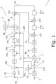
- Fig. 1
- schematisch das Fließbild einer vorschlagsgemäßen Anlage zur Ausführung des vorschlagsgemäßen Verfahrens gemäß einem Ausführungsbeispiel.
- Das vorschlagsgemäße Verfahren dient der Herstellung von Ammoniak 1 in einer Anlage 2 zur Herstellung von Ammoniak 1. Bei dem vorschlagsgemäßen Verfahren wird ein kohlenstoffhaltiger Energieträgerstrom 3 einer Synthesegasreaktoranordnung 4 zum Gewinnen eines Synthesegasstroms 5 mit Wasserstoff und Kohlenstoffoxiden zugeführt, wobei die Synthesegasreaktoranordnung 4 aus dem Energieträgerstrom 3 den Synthesegasstrom 5 durch eine autotherme Reformierung gewinnt. Hier stellt eine insbesondere katalytische partielle Oxidation die für die endothermen Reformierungsreaktionen erforderliche Wärme bereit. Insbesondere kann die Synthesegasreaktoranordnung 4 eine Synthesegasreaktorstufe 18 zum Gewinnen des Synthesegasstroms 5 aufweisen. Vorzugsweise umfasst die Anlage 2 die Synthesegasreaktoranordnung 4. Vorzugsweise umfasst der Energieträgerstrom 3 Erdgas oder besteht sogar im Wesentlichen aus Erdgas.
- Bei dem vorschlagsgemäßen Verfahren wird der Synthesegasstrom 5 einer Shiftvorrichtung 15a-c zugeführt, wobei in der Shiftvorrichtung 15a-c eine Wassergas-Shift-Reaktion zum Umsetzung zumindest eines Teils des Kohlenstoffmonoxids des Synthesegasstroms 5 mit Dampf des Synthesegasstroms 5 in Kohlenstoffdioxid und Wasserstoff stattfindet. Erkennbar umfasst der Synthesegasstrom 5 also Wasser.
- Bei dem vorschlagsgemäßen Verfahren wird weiter der Synthesegasstrom 5 der Shiftvorrichtung 15a-c prozesstechnisch nachgelagert zumindest teilweise einer Trennanordnung 6 zum Trennen des Synthesegasstroms 5 zumindest in einen Wasserstoffstrom 7 mit Wasserstoff und in einen Kohlenstoffoxide aufweisenden Abgasstrom 8 zugeführt wird, wobei der Wasserstoffstrom 7 zumindest teilweise sowie ein Stickstoffstrom 9 einer Ammoniak-Reaktoranordnung 10 zugeführt und dort in Ammoniak 1 umgewandelt wird. Anders ausgedrückt wird der Synthesegasstrom 5 der Trennanordnung 6 zugeführt, nachdem er der Shiftvorrichtung 15a-c zugeführt wurde. Dabei ist es nicht erforderlich und vorliegend auch nicht der Fall, dass der Synthesegasstrom 5 prozesstechnisch unmittelbar nach der Shiftvorrichtung 15a-c der Trennanordnung 6 zugeführt wird. Insbesondere ist eine unten näher beschriebene Kohlenstoffdioxidwäsche 30 zwischen der Shiftvorrichtung 15a-c und der Trennanordnung 6 vorgesehen. Es wird also der Wasserstoffstrom 7 zumindest teilweise der Ammoniak-Reaktoranordnung 10 zugeführt. Es kann sein, dass mehr als ein Wasserstoffstrom 7 sowie ggf. weitere Ströme aus der Trennanordnung 6 durch Trennen des Synthesegasstroms 5 gewonnen werden. In diesem Fall können auch die weiteren Wasserstoffströme 7 ganz oder teilweise der Ammoniak-Reaktoranordnung 10 zugeführt werden. Vorzugsweise umfasst die Anlage 2 die Trennanordnung 6, die Shiftvorrichtung 15a-c und/oder die Ammoniak-Reaktoranordnung 10.
- Vorzugsweise werden der Wasserstoffstrom 7 und der Stickstoffstrom 9 zusammengeführt und anschließend der Ammoniak-Reaktoranordnung 10 zugeführt. Insbesondere kann ein Ammoniak-Synthesegaskompressor 31 der Anlage 2 zur vorzugsweise gemeinsamen Druckerhöhung des Wasserstoffstroms 7 und des Stickstoffstroms 9 vorgesehen sein.
- Die autotherme Reformierung hat u.a. den Vorteil, dass sie zu einem hohen Druck des gewonnenen Synthesegasstroms 5 führt. Daher ist es bevorzugt, dass der Synthesegasstrom 5 von der Synthesegasreaktoranordnung 4 zur Trennanordnung 6 druckerhöhungsfrei geführt wird. Anders ausgedrückt findet keine Druckerhöhung des Synthesegasstroms 5 zwischen der Synthesegasreaktoranordnung 4 und der Trennanordnung 6 statt, wodurch die erheblichen Kosten für eine Kompressorstufe eingespart werden können.
- Die Trennanordnung 6 kann unterschiedliche Arten von Vorrichtungen umfassen. Gemäß einer ersten Möglichkeit umfasst die Trennanordnung 6 eine Adsorptionsvorrichtung zum Abtrennen von Wasserstoff, wobei es sich insbesondere - wie bei dem vorliegenden Ausführungsbeispiel - um eine Druckwechsel-Adsorptionsvorrichtung oder um eine Temperaturwechsel-Adsorptionsvorrichtung handeln kann. Alternativ oder zusätzlich kann die Trennanordnung auch eine Membranvorrichtung zum Abtrennen von Wasserstoff aufweisen.
- Das vorschlagsgemäße Verfahren ist dadurch gekennzeichnet, dass der Energieträgerstrom 3 vor Zuführung zur Synthesegasreaktoranordnung 4 einer Sättigungsstufe 11 zugeführt wird, in welcher Sättigungsstufe 11 dem Energieträgerstrom 3 vorgewärmtes Kondensat 12, welches in der Anlage 2 angefallen ist, zugeführt wird.
- Weiter ist das vorschlagsgemäße Verfahren dadurch gekennzeichnet, dass ein Dampfanteil des Synthesegasstroms 5 bei Zuführung zu der Shiftvorrichtung 15a-c zu mindestens 80 % bereits in der Synthesegasreaktoranordnung 4, insbesondere in der Synthesegasreaktorstufe 18, vorhanden ist. Anders ausgedrückt ist das Wasser, welches als Dampf in der Shiftvorrichtung 15a-c vorhanden ist, zu mindestens 80 % so zugeführt worden, dass es bereits in der Synthesegasreaktoranordnung 4 vorhanden war und danach Teil des Synthesegasstroms 5 wurde. Vorzugsweise ist der Dampfanteil des Synthesegasstroms 5 bei Zuführung zu der Shiftvorrichtung 15a-c zu mindestens 85 % und insbesondere zu mindestens 90 % bereits in der Synthesegasreaktoranordnung 4 vorhanden. Hier ist es weiter bevorzugt, dass der Dampfanteil des Synthesegasstroms 5 bei Zuführung zu der Shiftvorrichtung 15a-c zu mindestens 80 %, vorzugsweise zu mindestens 85 % und insbesondere zu mindestens 90 % auf das in der Sättigungsstufe 11 zugeführte Kondensat zurückgeht. Durch die Zuführung in der Sättigungsstufe 11 liegt das zugeführte Wasser zu dem entsprechenden Anteil als Dampf in der Synthesegasreaktoranordnung 4 vor.
- Bei dem Kondensat 12 handelt es sich um flüssiges Wasser, das durch Kondensation von gasförmigen Wasser in der Anlage 1 gewonnen wurde. Bei der Sättigungsstufe 11 handelt es sich um einen Vorrichtung, mit welcher flüssiges Wasser einem Gasstrom - hier speziell dem Energieträgerstrom 3 - zugeführt werden kann, sodass sich der Anteil an Dampf im dem jeweiligen Gasstrom, hier also dem Energieträgerstrom 3, erhöht. Der Vorteil gegenüber einer Zuführung von Hochdruckdampf liegt darin, dass dieser Hochdruckdampf nicht zusätzlich erzeugt werden muss. Im vorliegenden Ausführungsbeispiel wird das in den Wärmetauscherstufen 22a-c vorgewärmte Kondensat bei 260° Celsius auf einen Druck von 60 bar für die Zuführung zur Sättigungsstufe 11 gepumpt. Vorzugsweise umfasst die Anlage 2 die Sättigungsstufe 11.
- Bevorzugt ist weiter, dass bei der autothermen Reformierung in der Synthesegasreaktoranordnung 4 und insbesondere in der Synthesegasreaktorstufe 18 ein molares Dampf-zu-Kohlenstoff-Verhältnis von mindestens 1,5, vorzugsweise von mindestens 1,6, weiter vorzugsweise ein molares Dampf-zu-Kohlenstoff-Verhältnis von mindestens 2 und insbesondere ein molares Dampf-zu-Kohlenstoff-Verhältnis von mindestens 2,4, besteht. Je höher das Dampf-zu-Kohlenstoff-Verhältnis ist, umso geringer ist der Methanslip und umso wirksamer kann Kohlenstoffmonoxid bei der Wassergas-Shift-Reaktion in Kohlenstoffdioxid umgewandelt werden.
- Die nachstehende Tabelle gibt verschiedene Prozessparameter wieder, die sich bei unterschiedlichen molaren Dampf-zu-Kohlenstoff-Verhältnissen und einer bei 65 bar betriebenen autothermen Reformierung einstellen.
Dampf/C Verhältnis 1,2 1,6 2,0 2,4 2,8 3,0 CH4 Slip % 3,5% 2,5% 1,6% 1,2% 0,9% 0,8% Ausgang ATR trocken CO2 mol/mol 0,083 0,095 0,107 0,118 0,129 0,134 CO mol/mol 0,230 0,218 0,206 0,195 0,183 0,179 H2 mol/mol 0,651 0,661 0,668 0,673 0,677 0,680 Spez. Energieverbrauch GJ/t NH3 32,22 32,25 32,25 32,25 32,25 32,25 Carbon Recovery Rate % 80,4 85,7 89,2 91,4 93,0 93,5 Verbleibende CO2 Emission t CO2/t NH3 0,351 0,255 0,192 0,153 0,127 0,117 - Erkennbar ist, dass sich mit höherem Dampf-zu-Kohlenstoff-Verhältnis der Methanslip verringert. Ebenso erhöht sich der Anteil von Kohlenstoffdioxid und von Wasserstoff gegenüber dem von Kohlenstoffmonoxid im Synthesegas. Zwar findet eine leichte Erhöhung des Energieverbrauchs statt. Dies wird aber dadurch mehr als kompensiert, dass sich der Prozentsatz des rekuperierten Kohlenstoffdioxids stark erhöht. Im Ergebnis können auf diese Weise die CO2-Emissionen um bis zu 2/3 verringert werden.
- Grundsätzlich kann der Energieträgerstrom direkt der autothermen Reformierung zugeführt werden, sodass also das Gewinnen des Synthesegasstroms 5 aus einer autothermen Reformierung besteht. Das bedeutet, dass also keine Dampfreformierung beim Gewinnen des Synthesegasstroms 5 stattfindet. Eine bevorzugte Ausführungsform des vorschlagsgemäßen Verfahrens ist dadurch gekennzeichnet, dass die Synthesegasreaktoranordnung 4 einen Pre-Reformer 13, welcher vorzugsweise von der Anlage 2 umfasst ist, zum Aufspalten von Kohlenwasserstoffen mit mindestens zwei Kohlenstoffatomen in Methan aufweist. Der Pre-Reformer 13 ist insbesondere der Synthesegasreaktorstufe 18 prozesstechnische vorgeschaltet. Vorzugsweise erfolgt in dem Pre-Reformer 13 eine adiabatische Dampfreformierung über einem nickelbasierten Katalysator. Weiter ist bevorzugt, dass der Energieträgerstrom 3 vor Zuführung zur Sättigungsstufe 11 einer vorzugsweise von der Anlage 2 umfassten Entschwefelungsstufe 14 zur Entschwefelung des Energieträgerstroms 3 zugeführt wird. Ebenso ist es bevorzugt, dass das Gewinnen des Synthesegasstroms 5 aus der autothermen Reformierung und dem Pre-Reforming in dem Pre-Reformer 13 besteht. Dementsprechend findet dann keine herkömmliche Dampfreformierung bei dem Gewinnen des Synthesegasstroms 5 statt.
- Eine weitere bevorzugte Ausführungsform des vorschlagsgemäßen Verfahrens ist dadurch gekennzeichnet, dass der Synthesegasstrom 5 vor Zuführung zur Trennanordnung 6 einer Vielzahl von Shiftvorrichtungen 15a, b zugeführt wird, welche vorzugsweise prozesstechnisch zueinander beabstandet angeordnet sind und insbesondere von der Anlage 2 umfasst sein können. Das bedeutet, dass prozesstechnisch zwischen zwei Shiftvorrichtungen 15a, b mindestens eine weitere Vorrichtung angeordnet ist, bei welcher es sich nicht um eine Shiftvorrichtung 15a, b handelt. Auf diese Weise ist es möglich, den Synthesegasstrom 5 von einer Shiftvorrichtung 15a, b zur nächsten auf eine jeweils andere angepasste Temperatur zu bringen. Bevorzugt ist weiter, dass der den Shiftvorrichtungen 15a, b zugeführte Synthesegasstrom 5 in den Shiftvorrichtungen 15a, b jeweils eine Wassergas-Shift-Reaktion zur Umsetzung zumindest eines Teils des Kohlenstoffmonoxids des Synthesegasstroms 5 mit Dampf des Synthesegasstroms 5 in Kohlenstoffdioxid und Wasserstoff stattfindet.
- Gemäß einer bevorzugten Ausführungsform des vorschlagsgemäßen Verfahrens ist vorgesehen, dass in den Shiftvorrichtungen 15a, b die Wassergas-Shift-Reaktion jeweils in einem in Prozessrichtung abnehmenden Temperaturbereich stattfindet. Insbesondere kann es sein, dass die Shiftvorrichtungen 15a, b eine HT-Shiftvorrichtung 16 für eine Hochtemperatur-Wassergas-Shift-Reaktion und eine MT-Shiftvorrichtung 17 für eine Mitteltemperatur-Wassergas-Shift-Reaktion umfassen. Es kann alternativ oder zusätzlich auch sein, dass die Shiftvorrichtungen 15a, b eine NT-Shiftvorrichtung für eine Niedertemperatur-Wassergas-Shift-Reaktion umfassen. Dabei ist bevorzugt, dass prozesstechnisch die MT-Shiftvorrichtung 17 der HT-Shiftvorrichtung 16 folgt. Die NT-Shiftvorrichtung kann, falls vorgesehen, prozesstechnisch der MT-Shiftvorrichtung 17 folgen.
- Die Hochtemperatur-Wassergas-Shift-Reaktion findet bei einer Temperatur zwischen 300° C und 450° C statt. Die Mitteltemperatur-Wassergas-Shift-Reaktion findet bei einer Temperatur zwischen 220° C und 270° C statt. Die Niedertemperatur-Wassergas-Shift-Reaktion findet bei einer Temperatur zwischen 180° C und 250° C statt. Die Hochtemperatur-Wassergas-Shift-Reaktion hat für die Umwandlung in CO2 zwar ein schlechteres Reaktionsgleichgewicht, aber eine bessere Reaktionsgeschwindigkeit. Das hohe molares Dampf-zu-Kohlenstoff-Verhältnis verbessert das Reaktionsgleichgewicht. Durch diese Kaskadierung der Shiftvorrichtungen kann zunächst ein rascher Abbau von Kohlenstoffmonoxid erreicht werden, wobei die nachfolgenden Stufen sukzessive die verbliebenen Reste an Kohlenstoffmonoxid umwandeln. Da die Konzentration des Kohlenstoffmonoxids bereits verringert wurde, kann auch eine längere Reaktionszeit in Kauf genommen werden.
- Gemäß einer bevorzugten Ausführungsform des vorschlagsgemäßen Verfahrens ist vorgesehen, dass ein Dampfanteil des Synthesegasstroms 5 bei Zuführung zu einer prozesstechnisch ersten Shiftvorrichtung 15a der Shiftvorrichtungen 15a, b zu mindestens 90 % auf das in der Sättigungsstufe 11 zugeführte Kondensat zurückgeht. Auf diese Weise kann auf die Zufuhr von Dampf zum Erreichen des gewünschten Dampfanteils im Wesentlichen verzichtet werden. Zur genaueren Regelung des Dampf-zu-Kohlenstoff-Verhältnisses können Hochdruckdampfzufuhrvorrichtungen 19a-c entlang der Prozesstrecke vorgesehen sein. Diese können kleinere Mengen an Dampf zuführen.
- Eine bevorzugte Ausführungsform des vorschlagsgemäßen Verfahrens ist dadurch gekennzeichnet, dass der Synthesegasstrom 5 vor Zuführung zur Trennanordnung 6, vorzugsweise den Shiftvorrichtungen 15a, b prozesstechnisch nachgelagert, einer Kondensationsstufe 20 zum Gewinnen von Prozesskondensat 21 zugeführt wird. Vorzugsweise ist die Kondensationsstufe 20 von der Anlage 2 umfasst. Vorzugsweise wird der Synthesegasstrom 5 den Shiftvorrichtungen 15a, b prozesstechnisch nachgelagert der Kondensationsstufe 20 zugeführt. Anders ausgedrückt ist die Kondensationsstufe 20 prozesstechnisch den Shiftvorrichtungen 15a, b nachgelagert angeordnet. Bevorzugt ist weiter, dass das in der Sättigungsstufe 11 zugeführte Kondensat 12 das in der Kondensationsstufe 20 gewonnene Prozesskondensat 21 umfasst oder dass sogar das in der Sättigungsstufe 11 zugeführte Kondensat 12 im Wesentlichen aus dem in der Kondensationsstufe 20 gewonnenen Prozesskondensat 21 besteht. Besonders vorteilhaft ist es, wenn in der Kondensationsstufe 20 soviel Prozesskondensat 21 gewonnen wird, dass der Dampfanteil des Synthesegasstroms 5 bei Zuführung zu der Shiftvorrichtung 15a-c zu mindestens 80 %, vorzugsweise zu mindestens 85 % und insbesondere zu mindestens 90 % auf das Prozesskondensat 21 zurückgeht. Im Falle des Vorhandenseins einer Vielzahl von Shiftvorrichtungen 15a-c bezieht sich dies vorzugsweise auf die prozesstechnisch erste Shiftvorrichtung 15a der Shiftvorrichtungen 15a-c. Durch einen so hohen Anteil wird erreicht, dass das Prozesskondensat 21 im Wesentlichen vollständig in einem Kreislauf gefahren wird.
- Eine weitere bevorzugte Ausführungsform des vorschlagsgemäßen Verfahrens ist dadurch gekennzeichnet, dass der Synthesegasstrom 5 vor Zuführung zur Adsorptionsvorrichtung 6, vorzugsweise der Kondensationsstufe 20 vorgelagert, einer Vielzahl von Wärmetauscherstufen 22a-c zum Abkühlen des Synthesegasstroms zugeführt wird. Bevorzugt sind die Wärmetauscherstufen 22a-c von der Anlage 2 umfasst. Auf diese Weise kann der Synthesegasstrom 5 zum Erhöhen der Ausbeute an Prozesskondensat 21 abgekühlt werden. Vorzugsweise sind die Wärmetauscherstufen 22a-c zueinander prozesstechnisch beabstandet angeordnet. Insbesondere können die Wärmetauscherstufen 22a-c zumindest teilweise prozesstechnisch zwischen den Shiftvorrichtungen 15a-c angeordnet sein. Als besonders vorteilhaft hat sich die Variante erweisen, bei der eine prozesstechnisch erste Wärmetauscherstufe 22a prozesstechnisch der Synthesegasreaktoranordnung 4 nachgelagert und den Shiftvorrichtungen 15a, b vorgelagert angeordnet ist. Mit der prozesstechnisch ersten Wärmetauscherstufe 22a ist diejenige Wärmetauscherstufe gemeint, auf die der Synthesegasstrom 5 aus der Synthesegasreaktoranordnung 4 kommend prozesstechnisch als erstes trifft.
- Auf diese Weise kann die Temperatur des Synthesegasstroms 5 noch vor Erreichen der ersten Shiftvorrichtung 15a verringert und insbesondere exakt auf den optimalen Temperaturwert eingestellt werden. Grundsätzlich soll ja nach Abschluss der Wassergas-Shift-Reaktionen die Temperatur des Synthesegasstroms 5 für eine möglichst weit reichende Kondensation herabgesunken sein.
- Gemäß einer bevorzugten Ausführungsform des vorschlagsgemäßen Verfahrens ist vorgesehen, dass zumindest einem Teil der Wärmetauscherstufen 22a-c und vorzugsweise allen Wärmetauscherstufen 22a-c das Prozesskondensat 21 als Kühlmittel zugeführt wird. Insbesondere kann dadurch das Prozesskondensat 21 durch zumindest einen Teil und vorzugsweise durch alle Wärmetauscherstufen 22a-c vorgewärmt werden. Auf diese Weise kann im Ergebnis auch das in der Sättigungsstufe 11 zugeführte Kondensat 12 vorgewärmt werden. Bevorzugt ist weiter dass das Prozesskondensat 21 nacheinander den Wärmetauscherstufen 22a-c und anschließend der Sättigungsstufe 11 zugeführt wird. Dabei sind die Wärmetauscherstufen 22a-c vorzugsweise so eingerichtet, dass in der prozesstechnisch ersten Wärmetauscherstufe 22a keine Kondensation von Wasser aus dem Synthesegasstrom 5 erfolgt, die erste Wärmetauscherstufe 22a also kondensationsfrei bleibt.
- Grundsätzlich kann die Trennanordnung 6 mit einem beliebigen Wirkungsgrad der Trennung betrieben werden. Eine bevorzugte Ausführungsform des vorschlagsgemäßen Verfahrens ist dadurch gekennzeichnet, dass die Trennanordnung 6 einen Wirkungsgrad der Trennung von höchstens 90 % hat, sodass höchstens ein molarer Anteil von 90 % des Wasserstoffs aus dem Synthesegasstrom 5 von dem Wasserstoffstrom 7 umfasst ist. Dementsprechend können bis zu 10 % des molaren Anteils von Wasserstoff in dem Synthesegasstrom 5 von dem Abgasstrom 8 umfasst sein. Auf diese Weise erhöht sich der Stoffanteil in dem Abgasstrom 8, der zur Verfeuerung ohne CO2-Emission eingesetzt werden kann. Dies wird untenstehend noch beschrieben. Vorzugsweise hat die Trennanordnung 6 einen Wirkungsgrad der Trennung von höchstens 85 % oder sogar höchstens von 80 %, sodass höchstens ein molarer Anteil von 85 % des Wasserstoffs bzw. höchstens ein molarer Anteil von 80 % des Wasserstoffs aus dem Synthesegasstrom 5 von dem Wasserstoffstrom 7 umfasst ist. Damit steht im Abgasstrom 8 noch mehr Wasserstoff für die Verfeuerung zur Verfügung. Der Wirkungsgrad kann so eingestellt werden, dass im Abgasstrom 8 soviel Wasserstoff zur Verfügung gestellt werden kann, dass kein zusätzliches Erdgas verfeuert werden muss.
- Eine bevorzugte Ausführungsform des vorschlagsgemäßen Verfahrens ist dadurch gekennzeichnet, dass die Trennanordnung 6 mit einem im Wesentlichen maximalen Wirkungsgrad der Trennung betrieben wird und dass ein frisch gewonnener Wasserstoffverfeuerungsstrom zur Unterfeuerung eines oder mehrerer gasgefeuerte Einsatzstofferhitzer 26a-d verwendet wird. Bei einem hohen Wirkungsgrad der Trennanordnung 6 wird regelmäßig nicht genügend Wasserstoff im Abgasstrom 8 zum Erreichen der erforderlichen Brennleistung vorhanden sein. Ergänzend kann Wasserstoff aus dem Wasserstoffstrom 7 abgezweigt werden.
- Grundsätzlich kann die Synthesegasreaktoranordnung 4 auch mit Umgebungsluft betrieben werden. Eine weitere bevorzugte Ausführungsform des vorschlagsgemäßen Verfahrens ist jedoch dadurch gekennzeichnet, dass ein Sauerstoffstrom 23 aus einer Sauerstoffgewinnungsanordnung 24 der Synthesegasreaktoranordnung 4 zum Gewinnen des Synthesegasstroms 5 zugeführt wird. Der Sauerstoffgewinnungsanordnung 24 wird Umgebungsluft 32 zugeführt. Auf diese Weise resultiert ein niedrigerer Stickstoffanteil in dem Synthesegasstrom 5. Speziell gewinnt die Synthesegasreaktoranordnung 4 aus dem Energieträgerstrom 3 den Synthesegasstrom 5 durch eine autotherme Reformierung mit dem Sauerstoffstrom 23.
- Gemäß einer bevorzugten Ausführungsform des vorschlagsgemäßen Verfahrens ist vorgesehen, dass zumindest ein Teil der Kohlenstoffoxide aus dem Abgasstrom 8 durch einen Rückgewinnungsstrom 33 der Synthesegasreaktoranordnung 4 zugeführt wird. Damit wird erreicht, dass diese Kohlenstoffoxide jedenfalls zunächst nicht direkt oder im Falle des Kohlenstoffmonoxids nach Verbrennung in die Atmosphäre gelangen, sondern die vorherigen Prozessschritte wieder durchlaufen. Der Kohlenstoff in dem Rückgewinnungsstrom 33 kann dann, ggf. nach Umwandlung in Kohlenstoffdioxid, in der untenstehend näher beschriebenen Kohlenstoffdioxidwäsche ausgewaschen werden. Der Rückgewinnungsstrom 33 kann auf unterschiedliche Art und Weise aus dem Abgasstrom 8 gewonnen werden. Gemäß einer ersten Variante wird der Rückgewinnungsstrom 33 einfach aus dem Abgasstrom 8 abgezweigt, sodass der Rückgewinnungsstrom 33 im Wesentlichen die gleiche Zusammensetzung wie der Abgasstrom 8 aufweist.
- Die Zuführung des Rückgewinnungsstroms 33 kann insbesondere dadurch erfolgen, dass der Rückgewinnungsstrom 33 dem Energieträgerstrom 3 zugeführt wird. Insbesondere kann es sein, dass der Rückgewinnungsstrom 33 dem Energieträgerstrom 3 einem Erdgaskompressor 28 zur Druckerhöhung des Energieträgerstroms 3 prozesstechnisch vorgelagert zugeführt wird. Jedoch ist es auch denkbar, dass der Rückgewinnungsstrom 33 dem Energieträgerstrom 3 dem Erdgaskompressor 28 prozesstechnisch nachgelagert zugeführt wird. Vorzugsweise umfasst die Anlage 2 den Erdgaskompressor 28.
- Gemäß einer weiteren bevorzugten Ausführungsform des vorschlagsgemäßen Verfahrens ist vorgesehen, dass die Trennanordnung 6 aus dem Synthesegasstrom 5 auch einen, vorzugsweise wasserstoffhaltigen, Purgestrom 25 gewinnt, welcher insbesondere zur Unterfeuerung eines oder mehrerer gasgefeuerter Einsatzstofferhitzer 26a-d verwendet wird. Ein solcher gasgefeuerter Einsatzstofferhitzer 26a-d kann synonym auch als "fired heater" bezeichnet werden. Auch der Purgestrom 25 kann auf unterschiedliche Art und Weise gewonnen werden. Insbesondere kann der Purgestrom 25 aus dem Abgasstrom 8 gewonnen werden. Im vorliegenden Ausführungsbeispiel und bevorzugt werden der Rückgewinnungsstrom 33 und der Purgestrom 25 durch Aufteilen des Abgasstroms 8 gewonnen. Vorzugsweise umfasst die Anlage 2 den oder die mehreren gasgefeuerten Einsatzstofferhitzer 26a-d.
- Ebenso ist es möglich, dass der Abgasstrom 8 einer Druckwechsel-Adsorptionsvorrichtung oder einer Membranvorrichtung zugeführt wird. Aus der jeweiligen Vorrichtung kann dann als Strom mit einem höheren molaren Wasserstoffanteil der Purgestrom 25 und als Strom mit einem niedrigeren molaren Wasserstoffanteil der Rückgewinnungsstrom 33 gewonnen wird. Entsprechend weist der Purgestrom 25 bevorzugt einen niedrigeren molaren Anteil an Kohlenstoffmonoxid als der Rückgewinnungsstrom 33 auf.
- Eine bevorzugte Ausführungsform des vorschlagsgemäßen Verfahrens ist dadurch gekennzeichnet, dass der Wirkungsgrad der Trennanordnung 6 so eingestellt ist, dass durch den Wasserstoffgehalt des Purgestroms 25 ein dem gasgefeuerten Einsatzstofferhitzer 26a-d zugeführte Speisestrom 27a-d im Wesentlichen erdgasfrei ist. Der Speisestrom 27a-d stellt den Gasstrom dar, welcher in dem jeweiligen gasgefeuerten Einsatzstofferhitzer 26a-d verfeuert wird. Insbesondere kann der Speisestrom 27a-d den Purgestrom 25 ganz oder teilweise umfassen. Der Speisestrom 27a-d kann auch aus dem Purgestrom 25 oder aus einem Teil des Purgestroms 25 bestehen. Mit einem ausreichend hohen Wasserstoffgehalt in dem Purgestrom 25 kann durch das Verbrennen des Wasserstoffs ausreichend Hitze erzeugt werden, sodass die Verbrennung von Erdgas zum Erreichen der gewünschten Temperatur entbehrlich ist.
- Die Anlage 2 kann auch eine Vielzahl von gasgefeuerten Einsatzstofferhitzern 26a -d aufweisen. Im vorliegenden Ausführungsbeispiel dient ein erster gasgefeuerter Einsatzstofferhitzer 26a dem Erhitzen des Energieträgerstroms 3, wobei der erste gasgefeuerte Einsatzstofferhitzer 26a dem Erdgaskompressor 28 prozesstechnisch nachgelagert angeordnet ist. Der zweite gasgefeuerte Einsatzstofferhitzter 26b dient ebenfalls dem Erhitzen des Energieträgerstroms 3, ist aber prozesstechnisch zwischen der Sättigungsstufe 11 und dem Pre-Reformer 13 angeordnet. Auch der dritte gasgefeuerte Einsatzstofferhitzer 26c dient dem Erhitzen des Energieträgerstroms 3 und ist prozesstechnisch zwischen dem Pre-Reformer 13 und der Synthesegasreaktorstufe 18 angeordnet. Der vierte gasgefeuerte Einsatzstofferhitzer 26d schließlich dient dem Erhitzen eines Dampfstroms 29, welcher aus der Ammoniak-Reaktoranordnung 10 gewonnen wird.
- Eine weitere bevorzugte Ausführungsform des vorschlagsgemäßen Verfahrens ist dementsprechend dadurch gekennzeichnet, dass der Purgestrom 25 zur Unterfeuerung einer Vielzahl von gasgefeuerten Einsatzstofferhitzern 26a-d der Anlage 2 und insbesondere zur Unterfeuerung aller gasgefeuerten Einsatzstofferhitzer 26a-d der Anlage 2 verwendet wird. Zu diesem Zweck kann es sein, dass der jeweilige Speisestrom 27 a-d aus einer Unterteilung des Purgestroms 25 in eine Vielzahl von Speiseströmen 27a-d gewonnen wird. Auf diese Weise wird die bevorzugte Variante ermöglicht, nach der dass durch den Wasserstoffgehalt des Purgestroms 25 der allen gasgefeuerten Einsatzstofferhitzer 26a-d der Anlage zugeführte jeweilige Speisestrom 27a-d im Wesentlichen erdgasfrei ist. Es liegt auf der Hand, dass das die CO2-Abgabe der Anlage 2 wesentlich verringert.
- Gemäß einer bevorzugten Ausführungsform des vorschlagsgemäßen Verfahrens ist vorgesehen, dass der Synthesegasstrom 5 prozesstechnisch der Shiftvorrichtung 15a-c nachgelagert einer Kohlenstoffdioxidwäsche 30 zum Auswaschen mindestens eines Teiles des Kohlenstoffdioxids aus dem Synthesegasstrom 5 zugeführt wird. Das als Kohlenstoffdioxidstrom 34 ausgewaschene Kohlenstoffdioxid kann dann sequestriert oder anderweitig verwendet werden und wird jedenfalls nicht zwangsläufig in die Atmosphäre emittiert. Insbesondere ist vorgesehen, dass in der Kohlenstoffdioxidwäsche 30 das Kohlenstoffdioxid durch ein Methanol umfassendes Waschmedium ausgewaschen wird.
- Die vorschlagsgemäße Anlage dient zur Herstellung von Ammoniak 1 und weist eine Synthesegasreaktoranordnung 4 zum Gewinnen eines Synthesegasstroms 5 mit Wasserstoff und Kohlenstoffoxiden aus einem kohlenstoffhaltigen Energieträgerstrom 3 durch eine autotherme Reformierung auf. Eine eine vorzugsweise katalytische partielle Oxidation stellt die für die endothermen Reformierungsreaktionen erforderliche Wärme bereit.
- Die vorschlagsgemäße Anlage weist ferner eine Shiftvorrichtung 15a-c auf, welcher der Synthesegasstrom 5 zugeführt wird, wobei in der Shiftvorrichtung 15a-c eine Wassergas-Shift-Reaktion zur Umsetzung zumindest eines Teils des Kohlenstoffmonoxids des Synthesegasstroms 5 mit Dampf des Synthesegasstroms 5 in Kohlenstoffdioxid und Wasserstoff stattfindet.
- Die vorschlagsgemäße Anlage weist weiter eine prozesstechnisch der Shiftvorrichtung 15a-c nachgelagert angeordnete Trennanordnung 6 zum Trennen zumindest eines Teils des Synthesegasstroms 5 in einen Wasserstoffstrom 7 mit Wasserstoff und in einen Kohlenstoffoxide aufweisenden Abgasstrom 8 sowie eine Ammoniak-Reaktoranordnung 10 zum Umwandeln zumindest eines Teils eines Wasserstoffstroms 7 und eines Stickstoffstroms 9 in Ammoniak 1.
- Die vorschlagsgemäße Anlage ist dadurch gekennzeichnet, dass die Anlage 2 eine prozesstechnisch der Synthesegasreaktoranordnung 4 vorgelagerte Sättigungsstufe 11 zur Zufuhr von in der Anlage 2 angefallenem Kondensat 12 an den Energieträgerstrom 3 aufweist.
- Die vorschlagsgemäße Anlage ist weiter dadurch gekennzeichnet, dass ein Dampfanteil des Synthesegasstroms 5 bei Zuführung zu der Shiftvorrichtung 15a-c zu mindestens 80 % bereits in der Synthesegasreaktoranordnung 4 vorhanden ist.
- Vorstehend beschriebene bevorzugte Ausgestaltungen, Merkmale und Eigenschaften des vorschlagsgemäßen Verfahrens entsprechen bevorzugten Ausgestaltungen, Merkmalen und Eigenschaften der vorschlagsgemäßen Anlage und umgekehrt.
Claims (16)
- Verfahren zur Herstellung von Ammoniak (1) in einer Anlage (2) zur Herstellung von Ammoniak (1), wobei ein kohlenstoffhaltiger Energieträgerstrom (3) einer Synthesegasreaktoranordnung (4) zum Gewinnen eines Synthesegasstroms (5) mit Wasserstoff und Kohlenstoffoxiden zugeführt wird, wobei die Synthesegasreaktoranordnung (4) aus dem Energieträgerstrom (3) den Synthesegasstrom (5) durch eine autotherme Reformierung gewinnt, wobei der Synthesegasstrom (5) einer Shiftvorrichtung (15a-c) zugeführt wird, wobei in der Shiftvorrichtung (15a-c) eine Wassergas-Shift-Reaktion zur Umsetzung zumindest eines Teils des Kohlenstoffmonoxids des Synthesegasstroms (5) mit Dampf des Synthesegasstroms (5) in Kohlenstoffdioxid und Wasserstoff stattfindet, wobei der Synthesegasstrom (5) der Shiftvorrichtung (15a-c) prozesstechnisch nachgelagert zumindest teilweise einer Trennanordnung (6) zum Trennen des Synthesegasstroms (5) zumindest in einen Wasserstoffstrom (7) mit Wasserstoff und in einen Kohlenstoffoxide aufweisenden Abgasstrom (8) zugeführt wird, wobei ein Wasserstoffstrom (7) zumindest teilweise sowie ein Stickstoffstrom (9) einer Ammoniak-Reaktoranordnung (10) zugeführt und dort in Ammoniak (1) umgewandelt wird, dadurch gekennzeichnet, dass der Energieträgerstrom (3) vor Zuführung zur Synthesegasreaktoranordnung (4) einer Sättigungsstufe (11) zugeführt wird, in welcher Sättigungsstufe (11) dem Energieträgerstrom (3) vorgewärmtes Kondensat (12), welches in der Anlage (2) angefallen ist, zugeführt wird und dass ein Dampfanteil des Synthesegasstroms (5) bei Zuführung zu der Shiftvorrichtung (15a-c) zu mindestens 80 % bereits in der Synthesegasreaktoranordnung (4) vorhanden ist..
- Verfahren nach Anspruch 1, dadurch gekennzeichnet, dass die Synthesegasreaktoranordnung (4) einen Pre-Reformer (13) zum Aufspalten von Kohlenwasserstoffen mit mindestens zwei Kohlenstoffatomen in Methan aufweist, vorzugsweise, dass der Energieträgerstrom (3) vor Zuführung zur Sättigungsstufe (11) einer Entschwefelungsstufe (13) zur Entschwefelung des Energieträgerstroms (3) zugeführt wird.
- Verfahren nach Anspruch 1 oder Anspruch 2, dadurch gekennzeichnet, dass der Synthesegasstrom (5) vor Zuführung zur Trennanordnung (6) einer Vielzahl von, vorzugsweise prozesstechnisch beabstandet angeordneten, Shiftvorrichtungen (15a-c) zugeführt wird, und dass in den Shiftvorrichtungen (15a-c) jeweils eine Wassergas-Shift-Reaktion zur Umsetzung zumindest eines Teils des Kohlenstoffmonoxids des Synthesegasstroms (5) mit Dampf des Synthesegasstroms (5) in Kohlenstoffdioxid und Wasserstoff stattfindet.
- Verfahren nach Anspruch 3, dadurch gekennzeichnet, dass in den Shiftvorrichtungen (15a-c) die Wassergas-Shift-Reaktion jeweils in einem in Prozessrichtung abnehmenden Temperaturbereich stattfindet, vorzugsweise, dass die Shiftvorrichtungen (15a-c) eine HT-Shiftvorrichtung (16) für eine Hochtemperatur-Wassergas-Shift-Reaktion und eine MT-Shiftvorrichtung (17) für eine Mitteltemperatur-Wassergas-Shift-Reaktion umfassen.
- Verfahren nach Anspruch 3 oder 4, dadurch gekennzeichnet, dass ein Dampfanteil des Synthesegasstroms (5) bei Zuführung zu einer prozesstechnisch ersten Shiftvorrichtung (15a) der Shiftvorrichtungen (15a-c) zu mindestens 80 %, vorzugsweise mindestens 85 %, insbesondere mindestens 90 %, auf das in der Sättigungsstufe (11) zugeführte Kondensat zurückgeht.
- Verfahren nach einem der Ansprüche 1 bis 5, dadurch gekennzeichnet, dass der Synthesegasstrom (5) vor Zuführung zur Trennanordnung (6), vorzugsweise den Shiftvorrichtungen (15a-c) prozesstechnisch nachgelagert, einer Kondensationsstufe (20) zum Gewinnen von Prozesskondensat (21) zugeführt wird, vorzugsweise, dass das in der Sättigungsstufe (11) zugeführte Kondensat (12) das in der Kondensationsstufe (20) gewonnene Prozesskondensat (21) umfasst, insbesondere, dass das in der Sättigungsstufe (11) zugeführte Kondensat (12) im Wesentlichen aus dem in der Kondensationsstufe (20) gewonnenen Prozesskondensat (21) besteht.
- Verfahren nach einem der Ansprüche 1 bis 6, dadurch gekennzeichnet, dass der Synthesegasstrom (5) vor Zuführung zur Adsorptionsvorrichtung (6), vorzugsweise der Kondensationsstufe (20) vorgelagert, einer Vielzahl von Wärmetauscherstufen (22a-c) zum Abkühlen des Synthesegasstroms (5) zugeführt wird, vorzugsweise, dass die Wärmetauscherstufen (22a-c) zumindest teilweise prozesstechnisch zwischen den Shiftvorrichtungen (15a-c) angeordnet sind, insbesondere, dass eine prozesstechnisch erste Wärmetauscherstufe (22a) prozesstechnisch der Synthesegasreaktoranordnung (4) nachgelagert und den Shiftvorrichtungen (15a-c) vorgelagert angeordnet ist.
- Verfahren nach einem der Ansprüche 1 bis 7, dadurch gekennzeichnet, dass bei der autothermen Reformierung in der Synthesegasreaktoranordnung (4) ein molares Dampf-zu-Kohlenstoff-Verhältnis von mindestens 1,6, vorzugsweise ein molares Dampf-zu-Kohlenstoff-Verhältnis von mindestens 2, insbesondere ein molares Dampf-zu-Kohlenstoff-Verhältnis von mindestens 2,4, besteht.
- Verfahren nach einem der Ansprüche 1 bis 8, dadurch gekennzeichnet, dass die Trennanordnung (6) einen Wirkungsgrad der Trennung von höchstens 90 % hat, vorzugsweise von höchstens 85 % hat, sodass höchstens ein molarer Anteil von 10 % des Wasserstoffs, insbesondere höchstens ein molarer Anteil von 15 % des Wasserstoffs, aus dem Synthesegasstrom (5) von dem Wasserstoffstrom (7) umfasst ist.
- Verfahren nach einem der Ansprüche 1 bis 8, dadurch gekennzeichnet, dass die Trennanordnung (6) mit einem im Wesentlichen maximalen Wirkungsgrad der Trennung betrieben wird und dass ein frisch gewonnener Wasserstoffverfeuerungsstrom zur Unterfeuerung eines oder mehrerer gasgefeuerter Einsatzstofferhitzer (26a-d) verwendet wird.
- Verfahren einem der Ansprüche 1 bis 10, dadurch gekennzeichnet, dass ein Sauerstoffstrom (23) aus einer Sauerstoffgewinnungsanordnung (24) der Synthesegasreaktoranordnung (4) zum Gewinnen des Synthesegasstroms (5) zugeführt wird, vorzugsweise, dass die Synthesegasreaktoranordnung (4) aus dem Energieträgerstrom (3) den Synthesegasstrom (5) durch eine autotherme Reformierung mit dem Sauerstoffstrom (23) gewinnt.
- Verfahren nach einem der Ansprüche 1 bis 11, dadurch gekennzeichnet, dass zumindest ein Teil der Kohlenstoffoxide aus dem Abgasstrom (8) durch einen Rückgewinnungsstrom (33) der Synthesegasreaktoranordnung (4) zugeführt wird.
- Verfahren nach einem der Ansprüche 1 bis 12, dadurch gekennzeichnet, dass die Trennanordnung (6) aus dem Synthesegasstrom (5) auch einen, vorzugsweise wasserstoffhaltigen, Purgestrom (25) gewinnt, welcher insbesondere zur Unterfeuerung eines gasgefeuerten Einsatzstofferhitzers (26a-d) verwendet wird.
- Verfahren nach Anspruch 13, dadurch gekennzeichnet, dass der Wirkungsgrad der Trennanordnung (6) so eingestellt ist, dass durch den Wasserstoffgehalt des Purgestroms (25) ein dem gasgefeuerten Einsatzstofferhitzer (26a-d) zugeführte Speisestrom (27) im Wesentlichen erdgasfrei ist.
- Verfahren nach einem der Ansprüche 1 bis 14, dadurch gekennzeichnet, dass der Synthesegasstrom (5) prozesstechnisch der Shiftvorrichtung 15a-c nachgelagert einer Kohlenstoffdioxidwäsche (30) zum Auswaschen mindestens eines Teiles des Kohlenstoffdioxids aus dem Synthesegasstrom (5) zugeführt wird, insbesondere, dass in der Kohlenstoffdioxidwäsche (30) das Kohlenstoffdioxid durch ein Methanol umfassendes Waschmedium ausgewaschen wird.
- Anlage zur Herstellung von Ammoniak (1) mit einer Synthesegasreaktoranordnung (4) zum Gewinnen eines Synthesegasstroms (5) mit Wasserstoff und Kohlenstoffoxiden aus einem kohlenstoffhaltigen Energieträgerstrom (3) durch eine autotherme Reformierung, mit einer Shiftvorrichtung (15a-c), der der Synthesegasstrom (5) zugeführt wird, wobei in der Shiftvorrichtung (15a-c) eine Wassergas-Shift-Reaktion zur Umsetzung zumindest eines Teils des Kohlenstoffmonoxids des Synthesegasstroms (5) mit Dampf des Synthesegasstroms (5) in Kohlenstoffdioxid und Wasserstoff stattfindet, einer prozesstechnisch der Shiftvorrichtung (15a-c) nachgelagert angeordneten Trennanordnung (6) zum Trennen zumindest eines Teils des Synthesegasstroms (5) in einen Wasserstoffstrom (7) mit Wasserstoff und in einen Kohlenstoffoxide aufweisenden Abgasstrom (8) und mit einer Ammoniak-Reaktoranordnung (10) zum Umwandeln zumindest eines Teils eines Wasserstoffstroms (7) und eines Stickstoffstroms (9) in Ammoniak (1), dadurch gekennzeichnet, dass die Anlage (2) eine prozesstechnisch der Synthesegasreaktoranordnung (4) vorgelagerte Sättigungsstufe (11) zur Zufuhr von in der Anlage (2) angefallenem vorgewärmten Kondensat (12) an den Energieträgerstrom (3) aufweist und dass ein Dampfanteil des Synthesegasstroms (5) bei Zuführung zu der Shiftvorrichtung (15a-c) zu mindestens 80 % bereits in der Synthesegasreaktoranordnung (4) vorhanden ist.
Priority Applications (2)
| Application Number | Priority Date | Filing Date | Title |
|---|---|---|---|
| EP23175674.3A EP4467514A1 (de) | 2023-05-26 | 2023-05-26 | Verfahren und anlage zur herstellung von ammoniak |
| PCT/EP2024/064345 WO2024245920A1 (de) | 2023-05-26 | 2024-05-24 | Verfahren und anlage zur herstellung von ammoniak |
Applications Claiming Priority (1)
| Application Number | Priority Date | Filing Date | Title |
|---|---|---|---|
| EP23175674.3A EP4467514A1 (de) | 2023-05-26 | 2023-05-26 | Verfahren und anlage zur herstellung von ammoniak |
Publications (1)
| Publication Number | Publication Date |
|---|---|
| EP4467514A1 true EP4467514A1 (de) | 2024-11-27 |
Family
ID=86605141
Family Applications (1)
| Application Number | Title | Priority Date | Filing Date |
|---|---|---|---|
| EP23175674.3A Pending EP4467514A1 (de) | 2023-05-26 | 2023-05-26 | Verfahren und anlage zur herstellung von ammoniak |
Country Status (2)
| Country | Link |
|---|---|
| EP (1) | EP4467514A1 (de) |
| WO (1) | WO2024245920A1 (de) |
Citations (4)
| Publication number | Priority date | Publication date | Assignee | Title |
|---|---|---|---|---|
| EP2516326B1 (de) * | 2009-12-22 | 2014-10-29 | Johnson Matthey PLC | Umwandlung von kohlenwasserstoffen in kohlendioxid und strom |
| US20200055738A1 (en) | 2017-02-15 | 2020-02-20 | Casale Sa | Process for the synthesis of ammonia with low emissions of co2in atmosphere |
| WO2022003312A1 (en) * | 2020-06-30 | 2022-01-06 | Johnson Matthey Public Limited Company | Process for producing hydrogen |
| GB2597366A (en) * | 2020-06-30 | 2022-01-26 | Johnson Matthey Plc | Low-carbon hydrogen process |
-
2023
- 2023-05-26 EP EP23175674.3A patent/EP4467514A1/de active Pending
-
2024
- 2024-05-24 WO PCT/EP2024/064345 patent/WO2024245920A1/de not_active Ceased
Patent Citations (4)
| Publication number | Priority date | Publication date | Assignee | Title |
|---|---|---|---|---|
| EP2516326B1 (de) * | 2009-12-22 | 2014-10-29 | Johnson Matthey PLC | Umwandlung von kohlenwasserstoffen in kohlendioxid und strom |
| US20200055738A1 (en) | 2017-02-15 | 2020-02-20 | Casale Sa | Process for the synthesis of ammonia with low emissions of co2in atmosphere |
| WO2022003312A1 (en) * | 2020-06-30 | 2022-01-06 | Johnson Matthey Public Limited Company | Process for producing hydrogen |
| GB2597366A (en) * | 2020-06-30 | 2022-01-26 | Johnson Matthey Plc | Low-carbon hydrogen process |
Also Published As
| Publication number | Publication date |
|---|---|
| WO2024245920A1 (de) | 2024-12-05 |
Similar Documents
| Publication | Publication Date | Title |
|---|---|---|
| EP3954650B1 (de) | Verfahren und anlage zur herstellung von wasserstoff und abscheidung von kohlendioxid | |
| DE10334590B4 (de) | Verfahren zur Gewinnung von Wasserstoff aus einem methanhaltigen Gas, insbesondere Erdgas und Anlage zur Durchführung des Verfahrens | |
| EP4098610A1 (de) | Verfahren und anlage zum herstellen von reinwasserstoff durch dampfreformierung mit niedriger kohlendioxid-emission | |
| EP1751080A1 (de) | Koproduktion von methanol und ammoniak aus erdgas | |
| EP3323786B1 (de) | Verfahren zur kombinierten herstellung von methanol und ammoniak | |
| EP3176152B1 (de) | Verfahren zur erzeugung von harnstoff | |
| EP4201878A1 (de) | Verfahren zur wasserstofferzeugung mit geringer kohlendioxidemission | |
| EP3150549A1 (de) | Verfahren und anlage zur erzeugung von synthesegas mit variabler zusammensetzung | |
| WO2023208926A1 (de) | Verfahren und anlage zur herstellung von ammoniak | |
| EP4197967A1 (de) | Verfahren und anlage zum herstellen von methanol und kohlenmonoxid | |
| DE102022200572A1 (de) | Ammoniaksynthese und Harnstoffsynthese mit reduziertem CO2-Fußabdruck | |
| WO2024245920A1 (de) | Verfahren und anlage zur herstellung von ammoniak | |
| EP4610221A1 (de) | Verfahren und anlage zur bereitstellung eines wasserstoffstroms | |
| EP3075706A1 (de) | Verfahren und eine anlage zur erzeugung von synthesegas | |
| EP4556435B1 (de) | Verfahren und anlage zum speisen eines wasserstoffhaltigen gasstroms in eine pipeline | |
| DE102021210549A1 (de) | Verfahren zur Ammoniaksynthese und Anlage zur Herstellung von Ammoniak | |
| EP3674261B1 (de) | Verfahren zur synthese einer wasserstoffhaltigen verbindung | |
| EP4098609A1 (de) | Verfahren und anlage zum herstellen von reinwasserstoff durch dampfreformierung mit reduzierter kohlendioxid-emission | |
| EP0300151B1 (de) | Verfahren zur Herstellung von Ammoniak aus Erdgas | |
| BE1029787B1 (de) | Verfahren zur Ammoniaksynthese und Anlage zur Herstellung von Ammoniak | |
| EP4334242B1 (de) | Verfahren zur ammoniaksynthese und anlage zur herstellung von ammoniak | |
| DE3443017A1 (de) | Verfahren zur herstellung von ammoniaksynthesegas | |
| EP4349773A1 (de) | Verfahren und anlage zur herstellung eines wasserstoffprodukts | |
| WO2024230946A1 (de) | Verfahren und vorrichtung zur kohlendioxidarmen wasserstofferzeugung | |
| WO2026003052A1 (de) | Verfahren und anlage zum gewinnen eines wasserstoffstroms |
Legal Events
| Date | Code | Title | Description |
|---|---|---|---|
| PUAI | Public reference made under article 153(3) epc to a published international application that has entered the european phase |
Free format text: ORIGINAL CODE: 0009012 |
|
| STAA | Information on the status of an ep patent application or granted ep patent |
Free format text: STATUS: REQUEST FOR EXAMINATION WAS MADE |
|
| 17P | Request for examination filed |
Effective date: 20240226 |
|
| AK | Designated contracting states |
Kind code of ref document: A1 Designated state(s): AL AT BE BG CH CY CZ DE DK EE ES FI FR GB GR HR HU IE IS IT LI LT LU LV MC ME MK MT NL NO PL PT RO RS SE SI SK SM TR |