EP4467748A1 - Unité de plancher et structure de liaison de plancher - Google Patents
Unité de plancher et structure de liaison de plancher Download PDFInfo
- Publication number
- EP4467748A1 EP4467748A1 EP23201318.5A EP23201318A EP4467748A1 EP 4467748 A1 EP4467748 A1 EP 4467748A1 EP 23201318 A EP23201318 A EP 23201318A EP 4467748 A1 EP4467748 A1 EP 4467748A1
- Authority
- EP
- European Patent Office
- Prior art keywords
- floorboard
- unit
- groove
- connecting post
- recess
- Prior art date
- Legal status (The legal status is an assumption and is not a legal conclusion. Google has not performed a legal analysis and makes no representation as to the accuracy of the status listed.)
- Pending
Links
Images



Classifications
-
- E—FIXED CONSTRUCTIONS
- E04—BUILDING
- E04F—FINISHING WORK ON BUILDINGS, e.g. STAIRS, FLOORS
- E04F15/00—Flooring
- E04F15/02—Flooring or floor layers composed of a number of similar elements
- E04F15/02005—Construction of joints, e.g. dividing strips
-
- E—FIXED CONSTRUCTIONS
- E04—BUILDING
- E04F—FINISHING WORK ON BUILDINGS, e.g. STAIRS, FLOORS
- E04F15/00—Flooring
- E04F15/02—Flooring or floor layers composed of a number of similar elements
- E04F15/02005—Construction of joints, e.g. dividing strips
- E04F15/02016—Construction of joints, e.g. dividing strips with sealing elements between flooring elements
-
- E—FIXED CONSTRUCTIONS
- E04—BUILDING
- E04F—FINISHING WORK ON BUILDINGS, e.g. STAIRS, FLOORS
- E04F19/00—Other details of constructional parts for finishing work on buildings
- E04F19/02—Borders; Finishing strips, e.g. beadings; Light coves
- E04F19/06—Borders; Finishing strips, e.g. beadings; Light coves specially designed for securing panels or masking the edges of wall- or floor-covering elements
- E04F19/062—Borders; Finishing strips, e.g. beadings; Light coves specially designed for securing panels or masking the edges of wall- or floor-covering elements used between similar elements
-
- E—FIXED CONSTRUCTIONS
- E04—BUILDING
- E04F—FINISHING WORK ON BUILDINGS, e.g. STAIRS, FLOORS
- E04F19/00—Other details of constructional parts for finishing work on buildings
- E04F19/02—Borders; Finishing strips, e.g. beadings; Light coves
- E04F19/06—Borders; Finishing strips, e.g. beadings; Light coves specially designed for securing panels or masking the edges of wall- or floor-covering elements
- E04F19/065—Finishing profiles with a T-shaped cross-section or the like
-
- E—FIXED CONSTRUCTIONS
- E04—BUILDING
- E04F—FINISHING WORK ON BUILDINGS, e.g. STAIRS, FLOORS
- E04F2201/00—Joining sheets or plates or panels
- E04F2201/01—Joining sheets, plates or panels with edges in abutting relationship
- E04F2201/0153—Joining sheets, plates or panels with edges in abutting relationship by rotating the sheets, plates or panels around an axis which is parallel to the abutting edges, possibly combined with a sliding movement
-
- E—FIXED CONSTRUCTIONS
- E04—BUILDING
- E04F—FINISHING WORK ON BUILDINGS, e.g. STAIRS, FLOORS
- E04F2201/00—Joining sheets or plates or panels
- E04F2201/01—Joining sheets, plates or panels with edges in abutting relationship
- E04F2201/0153—Joining sheets, plates or panels with edges in abutting relationship by rotating the sheets, plates or panels around an axis which is parallel to the abutting edges, possibly combined with a sliding movement
- E04F2201/0161—Joining sheets, plates or panels with edges in abutting relationship by rotating the sheets, plates or panels around an axis which is parallel to the abutting edges, possibly combined with a sliding movement with snap action of the edge connectors
-
- E—FIXED CONSTRUCTIONS
- E04—BUILDING
- E04F—FINISHING WORK ON BUILDINGS, e.g. STAIRS, FLOORS
- E04F2201/00—Joining sheets or plates or panels
- E04F2201/05—Separate connectors or inserts, e.g. pegs, pins, keys or strips
Definitions
- the disclosure relates to the technical field of home improvement materials, in particular to a floorboard unit and a floorboard connecting structure.
- a floorboard as one of main ways of floor decoration, is widely used in homes, offices, receptions and other places.
- a wooden floorboard has characteristics of comfortable feet feeling, natural texture and recyclable materials, but shortcomings of the wooden floorboard are poor humidity resistance and anti-aging ability. High humidity is easy to make wood swell, while drying may cause the wood to shrink, which then leads to bulging, warping and others.
- a floorboard unit and a floorboard connecting structure are provided in the disclosure, which are simple and table in structure and with a firm splicing structure.
- a floorboard unit is provided in this disclosure, which includes a floorboard body and a connecting post.
- the connecting post is located at an end edge of a lower surface of the floorboard body, and an end of the connecting post is provided with a hooking part folded in a direction toward an end of the floorboard body, and the hooking part is of an approximate trapezoidal structure, and the hooking part is provided with an introduction sloping face for auxiliary clamping.
- the approximate trapezoidal hooking part is simple and stable in structure, which enables the connecting post to have strength and to produce tension with a floorboard connecting base.
- the introduction sloping face can assist in smoothly pressing downward and install the floorboard unit to be clamped into the floorboard connecting base, so as to be closely connected with the floorboard connecting base. After the hooking part of the floorboard unit is pressed into the floorboard connecting base, the hooking part can be locked, and closely connected, with a step block of a base body.
- the hooking part is bent to form a second included angle ⁇ of 90° to 135°, which can ensure stability of a connecting structure between the floorboard connecting base and the floorboard unit, and also make assembly and disassembly of the floorboard unit smoother.
- the introduction sloping face is a plane or a convex arc face, so that the floorboard unit can be smoothly dropped into an installation groove of the floorboard connecting base when pressed.
- an edge of an upper surface of the floorboard body is provided with a second chamfer, and a third chamfer is provided at a first recess of the floorboard body, which can assist stress release, avoid a sharp structure, and do not hurt hands during disassembly.
- a third chamfer is provided at a first recess of the floorboard body, which can assist stress release, avoid a sharp structure, and do not hurt hands during disassembly.
- it can provide an expansion deformation space for thermal expansion and contraction.
- the end edge of the lower surface of the floorboard body is provided with a second groove, and the connecting post is located in the second groove to divide the second groove into a first recess and a second recess.
- the connecting post does not protrude from the floorboard body, which is not easy to be damaged and is also more beautiful.
- the connecting post is located in a middle of the second groove.
- the connecting post is not located in a right middle of the second groove, but anywhere between two ends of the second groove, as long as the connecting post can be accommodated in the second groove.
- a bottom of the second recess is smoothly transitioned with an arc.
- the arc at the bottom of the second recess of the floorboard unit contacts with a first convex arc part of the floorboard connecting base to achieve smooth transition effect.
- a third convex arc part is provided at a side of the connecting post proximate to the second recess, and the third convex arc part and the hooking part are distributed in an oblique diagonal structure.
- a bottom of the first recess is provided with a fourth chamfer.
- the fourth chamfer can enhance stability of a part between the second chamfer and the third chamfer of the floorboard body.
- a floorboard connecting structure is further provided in the disclosure, which includes a floorboard connecting base and the floorboard unit described above.
- the floorboard connecting base includes an installation groove for accommodating the connecting post and a step block for clamping and matching with the hooking part.
- connection post there are at least two joint surfaces between the connecting post and an inner wall of the installation groove, which are formed by closely matching planes and/or the arc faces, and two of the at least two joint surfaces are distributed in a relative structure or an oblique diagonal structure.
- the connecting post of the floorboard unit and the floorboard connecting base are locked by a diagonal structure, with a stable clamping structure.
- the floorboard connecting base is further provided with a seam filling part.
- the seam filling part is able to be flush with the upper surface of the floorboard unit, thereby achieving the purpose of filling a seam between two adjacent floorboard units.
- the floorboard connecting structure further provides a floorboard connector having a transversal part and a longitudinal part, the transversal part and the longitudinal part are perpendicular to each other and cross, four curved parts are formed at the cross positions of the transversal part and the longitudinal part, and each of the curved part is provided with a first right-angle groove, and the first right-angle groove separates the floorboard connector to form a barrier wall and a first insertion block.
- the connecting post of the floorboard unit is inserted into the first right-angle groove of the floorboard connector, and the floorboard unit is provided with a second right-angle groove adapted to the first insertion block, i.e., and the first insertion block of the floorboard connector is inserted into the second right-angle groove of the floorboard unit, since the floorboard connector is a perpendicular cross-shape, it can assist four floorboard units to quickly find the position and be aligned, and the seams of four floorboard units are neater after paving, it can make the paving structure stable, and the floorboard unit is not easily shifted when in use.
- the disclosure has following beneficial effects.
- the floorboard unit according to the disclosure includes the floorboard body and the connecting post, and the end of the connecting post is folded to form the hooking part, so that the structure is simple and stable.
- the hooking part of the approximate trapezoidal structure makes the connecting post have strength, and produce tension with a floorboard connecting base. After the hooking part of the floorboard unit is pressed into the floorboard connecting base, the hooking part can be locked, and closely connected, with a step block of a base body.
- the floorboard connecting structure according to the disclosure is of a locking type, so it can be paved without glue due to a locking force, which is safe and environment-friendly and with tight joints.
- a whole structure may extend all around with change of temperature, and there will be no problems such as uplift or cracking due to the change of temperature, with good overall paving effect.
- a manual paving standard is replaced with an industrial standard, so that error of manual paving is reduced, and the floorboard can enter the groove by pressing or tapping the floorboard when paved, and its installation is simple.
- Reference numbers are as follows: 1. Floorboard Connecting Base; 10. Base Body; 11. Convex Part; 12. Limiting Part; 13. Installation Groove; 14. First Groove; 15. First Chamfer; 16. First Concave Arc Part; 17. Seam Filling Part; 111. First Convex Arc Part; 112. Second Convex Arc Part; 121. Step Block; 122. U-shaped Groove; 123. Second Concave Arc Part; 121a. First Sloping Face; 121b. End of Step Block; 121c. Step Surface;
- a floorboard connecting base 1 is provided in the present disclosure, which includes a base body 10, a convex part 11 and a limiting part 12.
- the convex part 11 and the limiting part 12 are located on an upper surface of the base body 10, and the convex part 11 and the limiting part 12 are arranged at intervals to form a mounting groove 13.
- a floorboard unit 2 is clamped into the mounting groove 13.
- a free end of the limiting part 12 is bent toward the convex part 11 to form a step block 121, which can form a semi-enclosed limiting structure for the inserted floorboard unit 2.
- the floorboard unit 2 can be stably matched, inserted and clamped with the floorboard connecting base 1, which is with a simple clamping structure and is suitable for diversity of floorboard paving and stable in structure.
- the base body 10 is provided with a first groove 14, and the first groove 14 is located below the convex part 11.
- the step block 121 and the convex part 11 can open to both sides. At this time, an elastic deformation space of the convex part 11 can be ensured when the first groove 14 is squeezed, which optimizes effect of pressing the floorboard unit 2 into the installation groove 13 and reduces use of materials.
- a bottom of the first groove 14 is arc-shaped, which can evenly disperse a pressure, and at the same time, it can also disperse internal stress so as to prevent stress concentration, avoid uneven deformation of the floorboard connecting base 1 and damage due to material fatigue.
- the base body 10 is provided with a first chamfer 15.
- a structure with the first chamfer 15 can achieve effect similar to that of the first groove 14.
- the first chamfer 15 is provided to cause a lower surface of the base body 10 to have a structure with a low middle part and two tilted ends, that is, an end of the lower surface of the base body 10 has a deformation space, which can also optimize effect of pressing products into the installation groove 13 and reduce the use of materials.
- a height of a step surface 121c of the step block 121 is not less than a height of the convex part 11.
- the limiting part 12 has good elasticity, and the connecting post 21 can smoothly enter the installation groove 13 during installation of the floorboard unit 2, and the limiting part can rebound in situ to lock the floorboard unit 2 when it is installed in place.
- the convex part 11 and the bottom of the installation groove 13 can be smoothly transitioned with a first concave arc part 16, so that the floorboard unit 2 can smoothly enter the installation groove 13.
- the first concave arc part 16 and the step surface of the step block 121 are distributed in an oblique diagonal structure.
- the number of the convex part 11 is two, the two convex parts 11 are located at the two ends of the upper surface of the base body 10, and the limiting part 12 is located between the two convex parts 11.
- the free end of the limiting part 12 is formed with two step blocks 121 bent in the direction of the two convex parts 11, respectively, so that two adjacent floorboard units 2 can be connected through the floorboard connecting base 1.
- the limiting part 12 is provided with a U-shaped groove 122 in a vertical direction.
- the step block 121 and the convex part 11 can open to both sides (as shown in FIGS. 8 and 11 ), and the U-shaped groove 122 can provide an elastic deformation space for the limiting part 12 when it is squeezed.
- a bottom of the U-shaped groove 122 is provided with a second concave arc part 123 which can increase structural stability and strength of the step block 121.
- a notch of the U-shaped groove 122 gradually expands outwards into a trumpet-shaped structure, which provides a larger deformation space for the step block 121.
- the connecting post 21 exerts a force on both the step block 121 and the convex part 11, and the lack of the first groove 14 or the first chamfer 15, i.e., the convex part 11 lacks an elastic deformation space, the limiting part 12 is prone to excessive deformation leading to the failure of the locking type connection structure; and the lack of the U-shaped groove 122, i.e., the limiting part 12 lacks an elastic deformation space, the convex part 11 is similarly susceptible to excessive deformation leading to the failure of the locking type connection structure.
- the U-shaped groove 122 of the limiting part 12 and the first groove 14 / the first chamfer 15 of the convex part 11 make the limiting part 12 and the convex part 11 have excellent elastic deformation ability in the direction of force, which not only ensures that the limiting part 12 and the convex part 11 are not easy to be damaged, but also ensures that the floorboard unit 2 is smoothly pressed into the floorboard connecting base 1, and that the paving efficiency is high.
- the step block 121 is of a stable triangular structure, and the step block 121 has a first sloping face 121a, and the first sloping face 121a is a plane or a convex arc face, so as to assist floorboard unit 2 in smoothly dropping into the installation groove 13 when pressed.
- a first included angle ⁇ between the step block 121 and the limiting part 12 is 90° to 135°, which can ensure stability of a connecting structure between the floorboard connecting base 1 and the floorboard unit 2, and also make assembly and disassembly of the floorboard unit 2 smoother.
- An end of the step block 121 is a convex circular arc, so a contact area between the floorboard unit 2 and the step block 121 is small, also with small friction resistance, which can also assist in smooth assembly and disassembly. If the first included angle ⁇ is less than 90°, and the floorboard unit 2 will be difficult to dismantle. If the first included angle ⁇ is greater than 135°, and the connection structure of the floorboard connecting base 1 and the floorboard unit 2 will be unstable.
- the convex part 11 is provided with a first convex arc part 111.
- the first convex arc part 111 contacts the connecting post 21 of the floorboard unit 2, which can assist smooth entry into the installation groove 13.
- the convex part 11 is further provided with a second convex arc part 112, which can also assist the floorboard unit 2 in being smoothly clamped with the floorboard connecting base 1.
- the floorboard connecting base is further provided with a seam filling part 17.
- the seam filling part 17 is disposed in a columnar structure in a vertical direction within the u-shaped groove 122, and the height of the seam filling part 17 is higher than that of the limiting part 12, so that after the floorboard unit 2 is installed, the seam filling part 17 is able to be flush with the upper surface of the floorboard unit 2, thereby achieving the purpose of filling a seam between two adjacent floorboard units 2.
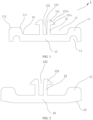
- a floorboard unit 2 which includes a floorboard body 20 and a connecting post 21.
- the connecting post 21 is located at an end edge of a lower surface of the floorboard body 20, and an end of the connecting post 21 is provided with a hooking part 211 folded in a direction toward an end of the floorboard body 20, and the hooking part 211 is of an approximate trapezoidal structure, and the hooking part 211 is provided with an introduction sloping face 211a for auxiliary clamping.
- the approximate trapezoidal hooking part 211 is simple and stable in structure, which enables the connecting post 21 to have strength and to produce tension with the floorboard connecting base 1.
- the introduction sloping face 211a can assist in smoothly pressing downward and install the floorboard unit 2 to be clamped into the floorboard connecting base 1, so as to be closely connected with the floorboard connecting base 1. After the hooking part 211 of the floorboard unit 2 is pressed into the floorboard connecting base 1, the hooking part 211 can be locked, and closely connected, with a step block 121 of a base body 10.
- the hooking part 211 is bent to form a second included angle ⁇ , and the second included angle ⁇ is 90° to 135°, which can ensure stability of a connecting structure between the floorboard connecting base 1 and the floorboard unit 2, and also make assembly and disassembly of the floorboard unit 2 smoother. If the second included angle ⁇ is less than 90°, and the floorboard unit 2 will be difficult to dismantle. If the second included angle ⁇ is greater than 135°, and the connection structure of the floorboard connecting base 1 and the floorboard unit 2 will be unstable.
- the introduction sloping face 211a is a plane or a convex arc face, so that the floorboard unit 2 can be smoothly dropped into an installation groove 13 of the floorboard connecting base 1 when pressed.
- an edge of an upper surface of the floorboard body 20 is provided with a second chamfer 23, and a third chamfer 221a is provided at a first recess 221 of the floorboard body 20, which can assist stress release, avoid a sharp structure, and do not hurt hands during disassembly. In addition, it can provide an expansion deformation space for thermal expansion and contraction.
- the end edge of the lower surface of the floorboard body 20 is provided with a second groove 22, and the connecting post 21 is located in the second groove 22 to divide the second groove 22 into a first recess 221 and a second recess 222.
- the connecting post 21 does not protrude from the floorboard body 20, which is not easy to be damaged and is also more beautiful.
- a bottom of the second recess 222 is smoothly transitioned with an arc, and contacts with the floorboard connecting base 1 to achieve smooth transition effect.
- a third convex arc part 212 is provided at a side of the connecting post 21 proximate to the second recess 222, and the third convex arc part 212 and the hooking part 211 are distributed in an oblique diagonal structure.
- a bottom of the first recess 221 is provided with a fourth chamfer 221b.
- the fourth chamfer 221b can enhance stability of a part between the second chamfer 23 and the third chamfer 221a of the floorboard body 20.
- a floorboard connecting structure 3 is further provided in the present disclosure, in which two adjacent floorboard units 2 (a first floorboard unit 2a and a second floorboard unit 2b) are connected through the floorboard connecting base 1.
- the connecting post 21 of the floorboard unit 2 is clamped into the installation groove 13, and the hooking part 211 of the connecting post 21 is engaged and matched with the step block 121 of the floorboard connecting base 1.
- the hooking part 211 of the floorboard unit 2 and the step block 121 are not easy to come off after locking and fastening each other, since the step block 121 of the floorboard connecting base 1 enters the first recess 221 of the floorboard unit 2.
- FIGS. 7 to 12 A specific installation process of the first floorboard unit 2a and the second floorboard unit 2b is shown in FIGS. 7 to 12 .
- the convex part 11 may act as a restriction for the first floorboard unit 2a and the second floorboard unit 2b in the horizontal direction.
- connection post 21 there are at least two joint surfaces between the connecting post 21 and an inner wall of the installation groove 13, which are formed by closely matching planes and/or arc faces, and two of the at least two joint surfaces are distributed in a relative structure or an oblique diagonal structure.
- the connecting post 21 of the floorboard unit 2 and the floorboard connecting base 1 are locked by a diagonal structure, with a stable clamping structure.
- two of the at least two joint surfaces are a horizontal face 31 and a first arc sloping face 32 distributed in an oblique diagonal structure, and a vertical face 33 is further included between the floorboard unit 2 and the floorboard connecting base 1.
- the horizontal plane 31 is formed by abutting of the step surface 121a of the step block 121 and the hooking part 211
- the first arc sloping face 32 is formed by abutting of the first concave arc part 16 of the floorboard connecting base 1 and the third convex arc part 212 of the floorboard unit 2.
- the first arc sloping face 32 has horizontal and vertical directions, which are opposite to the horizontal face 31 and the vertical face 33 respectively, and the limiting structure is stable.
- two of the at least two joint surfaces are a first arc sloping face 32 and a second arc sloping face 34 distributed in an oblique diagonal structure, and a vertical face 33 is further included between the floorboard unit 2 and the floorboard connecting base 1.
- the first arc sloping face 32 is formed by abutting of the first concave arc part 16 of the floorboard connecting base 1 and the third convex arc part 212 of the floorboard unit 2
- the second arc sloping face 34 is formed by abutting of the step block 121 and the hooking part 211.
- Both the first arc sloping face 32 and the second arc sloping face 34 have horizontal and vertical directions, and in combination with the vertical surface 33 for assisting in clamping, the limiting structure is stable.
- a slope of the introduction sloping face 211a is greater than that of a sloping face of the step block 121.
- the hooking part 211 When the hooking part 211 is pressed into the installation groove 13, it can contact with the sloping face of the step block 121.
- the slope of the introduction sloping face 211a is larger than that of the sloping face of the step block 121, a contact area between the step block 121 and the hooking part 211 can be reduced, thereby reducing friction effect, reducing elastic deformation of the limiting part 12 and avoiding structural failure of the limiting part 12 due to excessive deformation.
- the hooking part 211 after the hooking part 211 is clamped, it cooperates with the limiting part 12 to form a triangular gap, with a stable structure.
- various splicing structures can be constituted by the floorboard connecting base 1 and the floorboard unit 2 in the present disclosure.
- the floorboard unit 2 in the present disclosure has a consistent groove structure, which facilitates manufacturing.
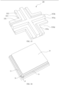
- the floorboard connecting structure 3 further provides a floorboard connector 35 having a transversal part 351 and a longitudinal part 352.
- the transversal part 351 and the longitudinal part 352 are perpendicular to each other and cross.
- Four curved parts 353 are formed at the cross positions of the transversal part 351 and the longitudinal part 352, and each of the curved part 353 is provided with a first right-angle groove 353a, and the first right-angle groove 353a separates the floorboard connector 35 to form a barrier wall 353b located at a middle portion and four first insertion blocks 353c of the right-angled structure.
- FIG. 16 it is shown that the floorboard unit 2 is rectangular, with a second right-angle groove 24 and a second insertion block 25 provided at least one right angle of the rectangle.
- Each curved part 353 is used for the insertion of one floorboard unit 2.
- the connecting post 21 of the floorboard unit 2 is inserted into the first right-angle groove 353a of the floorboard connector 35, respectively, and the first insertion block 353c of the floorboard connector 35 is inserted into the second right-angle groove 24 of the floorboard unit 2, while the second insertion block 25 of the floorboard unit 2 falls into a right-angle cavity 353d.
- the floorboard connector 35 is a perpendicular cross-shape, it can assist four floorboard units 2 to quickly find the position and be aligned, and the seams of four floorboard units 2 are neater after paving, it can make the paving structure stable, and the floorboard unit 2 is not easily shifted when in use.
- the height of the barrier wall 353b is greater than the height of the first insertion block 353c.
- the first insertion block 353c is shorter, which facilitates the insertion of the floorboard unit 2 into the floorboard connector 35, and the barrier wall 353b is higher which facilitates the restriction of the floorboard unit 2.
- the upper surface of the barrier wall 353b may be flat surface or convex curved surface. Referring to FIG. 17 , the middle of the barrier wall 353b is provided with a separating groove 353e along its length, which also reduces the use of materials while ensuring the structural soundness of the floorboard connector 35 and assisting in the quick alignment of the floorboard unit 2.
Landscapes
- Engineering & Computer Science (AREA)
- Architecture (AREA)
- Civil Engineering (AREA)
- Structural Engineering (AREA)
- Floor Finish (AREA)
Applications Claiming Priority (2)
| Application Number | Priority Date | Filing Date | Title |
|---|---|---|---|
| CN202310620865.7A CN116537487A (zh) | 2023-05-26 | 2023-05-26 | 一种地板单元及地板连接结构 |
| CN202310615849.9A CN116537486A (zh) | 2023-05-26 | 2023-05-26 | 一种地板连接基座及地板连接结构 |
Publications (1)
| Publication Number | Publication Date |
|---|---|
| EP4467748A1 true EP4467748A1 (fr) | 2024-11-27 |
Family
ID=88237374
Family Applications (1)
| Application Number | Title | Priority Date | Filing Date |
|---|---|---|---|
| EP23201318.5A Pending EP4467748A1 (fr) | 2023-05-26 | 2023-10-02 | Unité de plancher et structure de liaison de plancher |
Country Status (2)
| Country | Link |
|---|---|
| EP (1) | EP4467748A1 (fr) |
| WO (1) | WO2024244101A1 (fr) |
Citations (2)
| Publication number | Priority date | Publication date | Assignee | Title |
|---|---|---|---|---|
| EP1119671A1 (fr) * | 1998-10-06 | 2001-08-01 | Perstorp Flooring Ab | Materiau pour plancher comprenant des elements de plancher en forme de lames, assembles verticalement au moyen de profiles d'assemblage distincts |
| EP2813634A2 (fr) * | 2000-03-31 | 2014-12-17 | Pergo (Europe) AB | Matériau de plancher comprenant des éléments de plancher joints par des éléments de liaison |
Family Cites Families (6)
| Publication number | Priority date | Publication date | Assignee | Title |
|---|---|---|---|---|
| CN1757856A (zh) * | 2005-11-11 | 2006-04-12 | 圣象实业(深圳)有限公司 | 一种具条状扣件的可相互锁合的板材 |
| KR100762943B1 (ko) * | 2006-05-19 | 2007-10-02 | 주식회사 한솔홈데코 | 결합구를 이용한 조립식 바닥재 및 이의 조립 방법 |
| CN203924586U (zh) * | 2014-05-06 | 2014-11-05 | 李新发 | 弹性锁扣安装的地板 |
| CN111910880A (zh) * | 2020-08-27 | 2020-11-10 | 常州市德盛超硬工具有限公司 | 一种卡扣式活动木地板及其装配方法 |
| EP3985205A1 (fr) * | 2020-10-14 | 2022-04-20 | Jiangsu Alife Decorative Industry Co., Limited. | Plancher mobile en bois à emboîtement et procédé d'assemblage |
| US20220120092A1 (en) * | 2020-10-16 | 2022-04-21 | Jiangsu Ainafu Decoration Materials Co., Ltd. | Snap-type movable wooden floor and assembling method thereof |
-
2023
- 2023-06-30 WO PCT/CN2023/104669 patent/WO2024244101A1/fr not_active Ceased
- 2023-10-02 EP EP23201318.5A patent/EP4467748A1/fr active Pending
Patent Citations (2)
| Publication number | Priority date | Publication date | Assignee | Title |
|---|---|---|---|---|
| EP1119671A1 (fr) * | 1998-10-06 | 2001-08-01 | Perstorp Flooring Ab | Materiau pour plancher comprenant des elements de plancher en forme de lames, assembles verticalement au moyen de profiles d'assemblage distincts |
| EP2813634A2 (fr) * | 2000-03-31 | 2014-12-17 | Pergo (Europe) AB | Matériau de plancher comprenant des éléments de plancher joints par des éléments de liaison |
Also Published As
| Publication number | Publication date |
|---|---|
| WO2024244101A1 (fr) | 2024-12-05 |
Similar Documents
| Publication | Publication Date | Title |
|---|---|---|
| US7146772B2 (en) | Panel and locking system for panels | |
| WO2000063510A1 (fr) | Revetement de plancher constitue de panneaux de plancher et procede d'assemblage correspondant | |
| US20040250492A1 (en) | Device for assembling panel edges | |
| EP4467747A1 (fr) | Base de liaison de plancher et structure de liaison de plancher | |
| KR20120014759A (ko) | 데크 보드 교체방법 및 데크 보드 교체 연결구 | |
| US20060260252A1 (en) | Connection for laminate flooring | |
| US20240392583A1 (en) | Floorboard unit and floorboard connecting structure | |
| CN206000828U (zh) | 一种弹性榫卯结构及家具 | |
| CN219773441U (zh) | 一种快速插接型材组件 | |
| CN221682352U (zh) | 可调式地板龙骨快捷装配结构 | |
| CN220620795U (zh) | 一种装配式墙板的阳角连接件 | |
| CN116537487A (zh) | 一种地板单元及地板连接结构 | |
| CN209976999U (zh) | 板材隐形连接件 | |
| WO2024244101A1 (fr) | Unité de plancher et structure de liaison de plancher | |
| CN212078568U (zh) | 整体卫浴墙地交接圆角扣条 | |
| KR102856538B1 (ko) | 체결력을 향상시킨 바닥재 패널 조립 클립 | |
| CN108277954B (zh) | 自由扣地板 | |
| CN222541893U (zh) | 一种拼接地板的锁扣组件 | |
| CN223256196U (zh) | 一种钢结构连接头的锁紧装置 | |
| CN223151402U (zh) | 一种绿色建筑的保温墙体 | |
| CN219549283U (zh) | 板材拼接结构、中间板条以及边幅板条 | |
| US12398570B2 (en) | Floorboard with coupling structure | |
| CN114908934B (zh) | 一种光伏建筑系统 | |
| CN221399677U (zh) | 防止变形的地板及其结构件 | |
| CN219220260U (zh) | 一种纱网门窗紧固插角结构 |
Legal Events
| Date | Code | Title | Description |
|---|---|---|---|
| STAA | Information on the status of an ep patent application or granted ep patent |
Free format text: STATUS: EXAMINATION IS IN PROGRESS |
|
| PUAI | Public reference made under article 153(3) epc to a published international application that has entered the european phase |
Free format text: ORIGINAL CODE: 0009012 |
|
| 17P | Request for examination filed |
Effective date: 20231002 |
|
| AK | Designated contracting states |
Kind code of ref document: A1 Designated state(s): AL AT BE BG CH CY CZ DE DK EE ES FI FR GB GR HR HU IE IS IT LI LT LU LV MC ME MK MT NL NO PL PT RO RS SE SI SK SM TR |
|
| RIN1 | Information on inventor provided before grant (corrected) |
Inventor name: WANG, ZHIMING Inventor name: SHENG, CONGKUN Inventor name: DAI, HUIBIN |