EP4467848A1 - Soupape pneumatique, système pneumatique et véhicule, en particulier véhicule utilitaire - Google Patents
Soupape pneumatique, système pneumatique et véhicule, en particulier véhicule utilitaire Download PDFInfo
- Publication number
- EP4467848A1 EP4467848A1 EP23175644.6A EP23175644A EP4467848A1 EP 4467848 A1 EP4467848 A1 EP 4467848A1 EP 23175644 A EP23175644 A EP 23175644A EP 4467848 A1 EP4467848 A1 EP 4467848A1
- Authority
- EP
- European Patent Office
- Prior art keywords
- distribution channel
- air distribution
- pneumatic valve
- cylinder
- air
- Prior art date
- Legal status (The legal status is an assumption and is not a legal conclusion. Google has not performed a legal analysis and makes no representation as to the accuracy of the status listed.)
- Pending
Links
Images

Classifications
-
- F—MECHANICAL ENGINEERING; LIGHTING; HEATING; WEAPONS; BLASTING
- F16—ENGINEERING ELEMENTS AND UNITS; GENERAL MEASURES FOR PRODUCING AND MAINTAINING EFFECTIVE FUNCTIONING OF MACHINES OR INSTALLATIONS; THERMAL INSULATION IN GENERAL
- F16H—GEARING
- F16H61/00—Control functions within control units of change-speed- or reversing-gearings for conveying rotary motion ; Control of exclusively fluid gearing, friction gearing, gearings with endless flexible members or other particular types of gearing
- F16H61/26—Generation or transmission of movements for final actuating mechanisms
- F16H61/28—Generation or transmission of movements for final actuating mechanisms with at least one movement of the final actuating mechanism being caused by a non-mechanical force, e.g. power-assisted
- F16H61/30—Hydraulic or pneumatic motors or related fluid control means therefor
-
- F—MECHANICAL ENGINEERING; LIGHTING; HEATING; WEAPONS; BLASTING
- F15—FLUID-PRESSURE ACTUATORS; HYDRAULICS OR PNEUMATICS IN GENERAL
- F15B—SYSTEMS ACTING BY MEANS OF FLUIDS IN GENERAL; FLUID-PRESSURE ACTUATORS, e.g. SERVOMOTORS; DETAILS OF FLUID-PRESSURE SYSTEMS, NOT OTHERWISE PROVIDED FOR
- F15B15/00—Fluid-actuated devices for displacing a member from one position to another; Gearing associated therewith
- F15B15/08—Characterised by the construction of the motor unit
-
- F—MECHANICAL ENGINEERING; LIGHTING; HEATING; WEAPONS; BLASTING
- F15—FLUID-PRESSURE ACTUATORS; HYDRAULICS OR PNEUMATICS IN GENERAL
- F15B—SYSTEMS ACTING BY MEANS OF FLUIDS IN GENERAL; FLUID-PRESSURE ACTUATORS, e.g. SERVOMOTORS; DETAILS OF FLUID-PRESSURE SYSTEMS, NOT OTHERWISE PROVIDED FOR
- F15B13/00—Details of servomotor systems ; Valves for servomotor systems
- F15B13/02—Fluid distribution or supply devices characterised by their adaptation to the control of servomotors
-
- F—MECHANICAL ENGINEERING; LIGHTING; HEATING; WEAPONS; BLASTING
- F15—FLUID-PRESSURE ACTUATORS; HYDRAULICS OR PNEUMATICS IN GENERAL
- F15B—SYSTEMS ACTING BY MEANS OF FLUIDS IN GENERAL; FLUID-PRESSURE ACTUATORS, e.g. SERVOMOTORS; DETAILS OF FLUID-PRESSURE SYSTEMS, NOT OTHERWISE PROVIDED FOR
- F15B15/00—Fluid-actuated devices for displacing a member from one position to another; Gearing associated therewith
- F15B15/08—Characterised by the construction of the motor unit
- F15B15/14—Characterised by the construction of the motor unit of the straight-cylinder type
- F15B15/1423—Component parts; Constructional details
- F15B15/1428—Cylinders
-
- F—MECHANICAL ENGINEERING; LIGHTING; HEATING; WEAPONS; BLASTING
- F16—ENGINEERING ELEMENTS AND UNITS; GENERAL MEASURES FOR PRODUCING AND MAINTAINING EFFECTIVE FUNCTIONING OF MACHINES OR INSTALLATIONS; THERMAL INSULATION IN GENERAL
- F16H—GEARING
- F16H61/00—Control functions within control units of change-speed- or reversing-gearings for conveying rotary motion ; Control of exclusively fluid gearing, friction gearing, gearings with endless flexible members or other particular types of gearing
- F16H61/0003—Arrangement or mounting of elements of the control apparatus, e.g. valve assemblies or snapfittings of valves; Arrangements of the control unit on or in the transmission gearbox
-
- F—MECHANICAL ENGINEERING; LIGHTING; HEATING; WEAPONS; BLASTING
- F16—ENGINEERING ELEMENTS AND UNITS; GENERAL MEASURES FOR PRODUCING AND MAINTAINING EFFECTIVE FUNCTIONING OF MACHINES OR INSTALLATIONS; THERMAL INSULATION IN GENERAL
- F16K—VALVES; TAPS; COCKS; ACTUATING-FLOATS; DEVICES FOR VENTING OR AERATING
- F16K31/00—Actuating devices; Operating means; Releasing devices
- F16K31/12—Actuating devices; Operating means; Releasing devices actuated by fluid
- F16K31/122—Actuating devices; Operating means; Releasing devices actuated by fluid the fluid acting on a piston
-
- F—MECHANICAL ENGINEERING; LIGHTING; HEATING; WEAPONS; BLASTING
- F16—ENGINEERING ELEMENTS AND UNITS; GENERAL MEASURES FOR PRODUCING AND MAINTAINING EFFECTIVE FUNCTIONING OF MACHINES OR INSTALLATIONS; THERMAL INSULATION IN GENERAL
- F16K—VALVES; TAPS; COCKS; ACTUATING-FLOATS; DEVICES FOR VENTING OR AERATING
- F16K31/00—Actuating devices; Operating means; Releasing devices
- F16K31/12—Actuating devices; Operating means; Releasing devices actuated by fluid
- F16K31/122—Actuating devices; Operating means; Releasing devices actuated by fluid the fluid acting on a piston
- F16K31/1225—Actuating devices; Operating means; Releasing devices actuated by fluid the fluid acting on a piston with a plurality of pistons
-
- B—PERFORMING OPERATIONS; TRANSPORTING
- B60—VEHICLES IN GENERAL
- B60Y—INDEXING SCHEME RELATING TO ASPECTS CROSS-CUTTING VEHICLE TECHNOLOGY
- B60Y2200/00—Type of vehicle
- B60Y2200/10—Road Vehicles
- B60Y2200/14—Trucks; Load vehicles, Busses
-
- B—PERFORMING OPERATIONS; TRANSPORTING
- B60—VEHICLES IN GENERAL
- B60Y—INDEXING SCHEME RELATING TO ASPECTS CROSS-CUTTING VEHICLE TECHNOLOGY
- B60Y2200/00—Type of vehicle
- B60Y2200/90—Vehicles comprising electric prime movers
- B60Y2200/91—Electric vehicles
-
- B—PERFORMING OPERATIONS; TRANSPORTING
- B60—VEHICLES IN GENERAL
- B60Y—INDEXING SCHEME RELATING TO ASPECTS CROSS-CUTTING VEHICLE TECHNOLOGY
- B60Y2400/00—Special features of vehicle units
- B60Y2400/40—Actuators for moving a controlled member
- B60Y2400/408—Pneumatic actuators
-
- F—MECHANICAL ENGINEERING; LIGHTING; HEATING; WEAPONS; BLASTING
- F16—ENGINEERING ELEMENTS AND UNITS; GENERAL MEASURES FOR PRODUCING AND MAINTAINING EFFECTIVE FUNCTIONING OF MACHINES OR INSTALLATIONS; THERMAL INSULATION IN GENERAL
- F16H—GEARING
- F16H61/00—Control functions within control units of change-speed- or reversing-gearings for conveying rotary motion ; Control of exclusively fluid gearing, friction gearing, gearings with endless flexible members or other particular types of gearing
- F16H61/26—Generation or transmission of movements for final actuating mechanisms
- F16H61/28—Generation or transmission of movements for final actuating mechanisms with at least one movement of the final actuating mechanism being caused by a non-mechanical force, e.g. power-assisted
- F16H61/30—Hydraulic or pneumatic motors or related fluid control means therefor
- F16H2061/307—Actuators with three or more defined positions, e.g. three position servos
Definitions
- the disclosure relates to a pneumatic valve for a pneumatic system of a vehicle, in particular utility vehicle, wherein the pneumatic valve comprises a cylinder and a main piston arranged within the cylinder, the cylinder comprises an end face with an air distribution channel being connected to an air inlet and being adapted to deliver pressurized air to move the main piston within the cylinder.
- the disclosure further relates to a pneumatic system for a vehicle, in particular utility vehicle, comprising a pneumatic valve, and to a vehicle, in particular utility vehicle, comprising a pneumatic system.
- Pneumatic valves are known in the prior art. Pneumatic valves may be controlled by the application of pressurized air. The application of pressurized air may lead to a deflection of one or more pistons. The deflection of the one or more pistons may be reciprocated by a stroke of an actuator. The actuator may actuate a component in a pneumatic system and/or change a state thereof.
- Such an end position may be a position in which a piston is too close to and/or even contacting the end face of the cylinder, e.g., a fully extended position or, if the valve comprises an auxiliary piston, a partly extended position at which the main piston contacts the end face.
- This may cause, upon the application of pressurized air, a non-uniform air distribution between the piston and the end face.
- the non-uniform air distribution may result in uneven force acting on the piston for deflecting the piston at the very beginning of the stroke of the actuator.
- Such a three-position actuator usually comprises one or more auxiliary pistons which increase the complexity of the valve and the vulnerability to an uneven air distribution that may cause tilting or other misbehaviors.
- An embodiment of the present disclosure may solve the problem of enabling an even air distribution between a piston and an end face of a pneumatic valve, while avoiding introducing a large amount of dead volume between the piston and the end face.
- a pneumatic valve for a pneumatic system of a vehicle in particular utility vehicle
- the pneumatic valve comprises a cylinder and a main piston arranged within the cylinder
- the cylinder comprises an end face with an air distribution channel being connected to an air inlet and being adapted to deliver pressurized air to move the main piston within the cylinder
- the air distribution channel is adapted to deliver pressurized air to an inner section and to an outer section being arranged radially outwardly from the inner section and between the main piston and the end face, wherein the air distribution channel is adapted to deliver pressurized air to the inner section and to the outer section alternatingly.
- the cylinder may be adapted to be deflected, i.e., to move along an axis, within the cylinder under the application of the pressurized air.
- the axis may be defined as a respective cylinder axis of the cylinder and/or the piston.
- the arrangement of the inner section and of the outer section may be, in a radial direction, defined by the axis. I.e., the inner section may be arranged between the axis and the outer section. In the axial direction, the inner section and the outer section is arranged between the main piston and the end face. This enables that, in an end stop position, pressurized air may be delivered between the main piston and the end face to deflect the main piston.
- the air distribution channel When pressurized air is applied the air distribution channel may be considered as a route of least resistance for the pressurized air. Thus, pressurized air may be distributed within the air distribution channel upon the application of the pressurized air.
- the air distribution channel is decisive for the onset of the deflection of the main piston.
- the alternating air distribution channel may provide uniform air distribution underneath the piston of the pneumatic actuator, i.e., between the end face and the piston, at the beginning of the stroke starting from an end position, even if the cylinder bottom acts as a hard end stop.
- the air distribution channel is adapted to deliver pressurized air to the inner section and to the outer section alternatingly.
- the alternating delivery of pressurized air to the inner section and to the outer section avoids that the air distribution channel delivers pressurized air to a connected and circumferential volume between the main piston and the end face which spans along its circumference from an inner diameter to an outer diameter. This reduces the volume of the air distribution channel and may thus improve the performance of the pneumatic valve.
- the air distribution channel is alternatingly arranged between an inner diameter and an outer diameter of the cylinder.
- the air distribution channel is adapted to deliver pressurized air to the inner diameter and to the outer diameter alternatingly. I.e., along a contour of the air distribution channel, the air distribution channel extends to the inner diameter but not to the outer diameter, then to the outer diameter but not to the inner diameter, and so forth. This may reduce the dead volume compared to an air distribution channel extending between the inner and the outer diameter along a circumference, i.e., the contour of the air distribution channel.
- the air distribution channel comprises a zig-zag-shaped, a meandering and/or undulated contour.
- Each of the zig-zag-shaped, the meandering and/or the undulated contour may enable the air distribution channel to deliver pressurized air to the inner section and to the outer section alternatingly. This achieves a proper air distribution while avoiding unnecessary dead volume.
- the zig-zag-shaped, the meandering and/or the undulated contour may define a radial extension and/or arrangement of the air distribution channel in dependence on a circumferential coordinate.
- the cylinder defines an axis and the air distribution channel is partially or entirely circumferentially arranged at the end face.
- a circumferential arrangement of the air distribution channel achieves a homogeneous application of pressurized air.
- this may also be essentially achieved with a partial circumferential arrangement of the air distribution channel.
- the partial circumferential arrangement may result from ribs being arranged at the end face which may, e.g., project into the channel. Such ribs could improve the manufacture of the cylinder but may not be necessary for the functioning of air distribution channel.
- the air distribution channel comprises a plurality of delivery sections, and the air distribution channel is adapted to deliver pressurized air to each of the inner section and to the outer section at one of the plurality of delivery sections.
- the air distribution channel comprises dedicated delivery section to apply pressurized air.
- the delivery section may be defined by radially inner sections of the air distribution channel to deliver pressurized air to the inner sections and radially outer sections of the air distribution channel to deliver pressurized air to the outer sections.
- the pneumatic valve comprises an auxiliary piston being arranged radially outwardly from the main piston, and the outer section is adapted to deliver pressurized air to the auxiliary piston.
- the outer section may be adapted to deliver pressurized air between the auxiliary piston and the end face.
- the end face comprises a connecting portion adapted to interconnect the air distribution channel and the air inlet, and the connecting portion comprises a larger radial extension than the air distribution channel.
- the connecting portion may enable a more efficient manufacturing, e.g., by milling. For this reason, the connecting portion may be convex and curved, e.g., round and/or oval.
- the cross-section of the air distribution channel may differ from the cross-section and/or shape of the connecting portion. E.g., the cross-section of the air distribution channel may be U-shaped and/or V-shaped.
- a pneumatic system for a vehicle in particular utility vehicle
- the pneumatic system comprises the pneumatic valve as described above.
- the pneumatic valve comprises one or more of the above-described optional features to achieve a corresponding technical effect.
- the pneumatic system is an automated manual transmission.
- This may be a particular useful application for such a valve.
- the automated manual transmission may advantageously benefit from the improved performance of the pneumatic valve.
- the pneumatic valve may be used in other pneumatic systems, such as a pneumatic suspension system and/or a pneumatic braking system.
- a vehicle in particular utility vehicle
- the vehicle comprises the pneumatic system as described above.
- the pneumatic system and/or the pneumatic valve of the pneumatic system comprises one or more of the above-described optional features to achieve a corresponding technical effect.
- FIG 1 shows a schematic of a vehicle 200a, in particular utility vehicle 200b, according to an embodiment of the disclosure.
- vehicle 200a in particular utility vehicle 200b
- vehicle 200a, 200b is referred to as vehicle 200a, 200b.
- the vehicle 200a, 200b is a land-vehicle.
- the vehicle 200a, 200b may be a truck, a bus and/or a trailer.
- the vehicle 200a, 200b comprises a pneumatic system 250.
- the pneumatic system 250 is an automated manual transmission 250a.
- the automated manual transmission 250a is adapted to switch gears, e.g., of an electric drive integrated into one of a plurality of axles (not shown), so called e-axles, of the vehicle 200a, 200b.
- the pneumatic system 250 comprises a pneumatic valve 100.
- the pneumatic system 250 is adapted to supply pressurized air to the pneumatic valve 100.
- the pneumatic valve 100 is a three-position actuator 100'.
- the pneumatic valve 100 is further described with reference to Figures 4 and 5 .
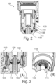
- Figure 2 shows a cross-sectional view of a pneumatic valve 100 according to the prior art.
- the pneumatic valve 100 comprises a cylinder 110 and a movable piston 120 within the cylinder 110.
- the motion of the piston 120 may imply a stroke of an actuator 150.
- the pneumatic valve 100 comprises an air inlet 135 via which pressurized air may be applied.
- the cylinder 110 comprises an end face 113.
- the air inlet 135 is arranged at the end face 135 so that pressurized air may be delivered between the end face 135 and the piston 120 to deflect the piston 120.
- the valve 100 is illustrated in the extended position. I.e., the piston 120 is arranged at an end stop and the actuator 150 is extended, i.e., projects maximally from the cylinder 110.
- the actuator 150 may be retracted when pressurized air is supplied and the piston 120 is deflected.
- the piston 120 In the end stop position, the piston 120 contacts the end face 113. Pressurized air may inhomogeneously and non-uniformly distribution between the end face 113 and the main piston 120 which leads to risk of sticking and/or increased friction between the piston 120 and the cylinder 110.
- Figure 3 shows a cross-sectional view of a pneumatic valve 100 and a perspective sectional view of a cylinder 110 of a pneumatic valve 100 according to the prior art.
- Figure 3 (A) shows the cross-sectional view of the pneumatic valve 100
- Figure 3 (B) shows the perspective sectional view of the cylinder 110 of the pneumatic valve 100, i.e., in Figure 3 (B) the piston 120 is schematically removed for clearer illustration.
- the pneumatic valve 100 comprises a cylinder 110 and a movable piston 120 within the cylinder 110.
- the motion of the piston 120 may imply a stroke of an actuator 150.
- the pneumatic valve 100 comprises an air inlet 135 via which pressurized air may be applied.
- the cylinder 110 comprises an end face 113.
- the air inlet 135 is arranged at the end face 113 so that pressurized air may be delivered between the end face 113 and the piston 120 to deflect the piston 120.
- the valve 100 is illustrated in the extended position. I.e., the piston 120 is arranged at an end stop and the actuator 150 is extended, i.e., projects maximally from the cylinder 110.
- the actuator 150 may be retracted when pressurized air is supplied and the piston 120 is deflected.
- the cylinder 110 comprises an air distribution channel 130.
- the air distribution channel 130 is arranged at the end face 113.
- the air inlet 135 is adapted to deliver pressurized air in the air distribution channel 130.
- the air distribution channel 130 is circumferentially arranged at the end face of the cylinder 110.
- the air distribution channel 130 extends from an inner diameter (not indicated) to an outer diameter (not indicated) so that a to a connected and circumferential volume between the piston 120 and the end face 113 which spans along its circumference from the inner diameter to the outer diameter is provided.
- the simple air distribution channel 130 leads to a comparatively large dead volume, i.e., the volume of the air distribution channel 130, which may impede the performance of the valve 100.
- Figure 4 shows a sectional view and a perspective view of details of a pneumatic valve 100 according to an embodiment of the disclosure.
- the pneumatic valve 100 is a pneumatic valve 100 for a pneumatic system 250 of a vehicle 200a, 200b. Such a vehicle 200a, 200b and pneumatic system 250 is described with reference to Figure 1 .
- Figure 4 is described under reference to Figure 1 .
- Figure 4 (A) shows the sectional view of the pneumatic valve 100
- Figure 4 (B) shows perspective view of details of a pneumatic valve 100, in particular of an end face 113 and an air distribution channel 130.
- the relation between Figures 4 (A) and (B) is schematically indicated by two arrows between Figures 4 (A) and (B) .
- the pneumatic valve 100 is a three-position actuator 100'.
- the pneumatic valve 100 comprises an actuator 150, e.g., a push rod, which may be deflected in one of three positions by the application of pressurized air.
- the pneumatic valve 100 comprises a cylinder 110.
- the cylinder 110 is also called body of the pneumatic valve 100 and/or being comprised by the body.
- the pneumatic valve 100 comprises a main piston 120 and an auxiliary piston 140, each arranged within the cylinder 110.
- Each of the cylinder 110, the main piston 120 and the auxiliary piston 140 defines an axis A.
- the auxiliary piston 140 is arranged radially outwardly from the main piston 120.
- Each of the main piston 120 and the auxiliary piston 140 is adapted to move in an axial direction along the axis A. The movement of the main piston 120 and the auxiliary piston 140 reciprocates to the deflection of the actuator 150.
- the cylinder 110 comprises an end face 113 with an air distribution channel 130 being connected to an air inlet 135 (see Figure 5 ) and being adapted to deliver pressurized air to move the main piston 120 and/or the auxiliary piston 140 within the cylinder 110.
- an inner section 121 and an outer section 131 is defined.
- the inner section 121 is radially inwardly arranged from the outer section 131.
- Each of the inner section 121 and the outer section 131 is arranged, in the axial direction, between the main piston 120 and the end face 113.
- the air distribution channel 130 is adapted to deliver pressurized air to the inner section 121 and to the outer section 111, see also Figure 4 (B) .
- the air distribution channel 130 is adapted to deliver pressurized air to the inner section 121 and to the outer section 111 alternatingly.
- the air distribution channel 130 comprises a plurality of delivery sections 132, and the air distribution channel 130 is adapted to deliver pressurized air to each of the inner section 121 and to the outer section 111 at one of the plurality of delivery sections 132.
- each of the delivery sections 132 is arranged, in radial direction, at the inner section 121 or at the outer section 111.
- the cylinder 110 and/or the end face 113 defines a diameter, as a radial extension.
- the cylinder 110 defines an inner diameter d i and an outer diameter d o .
- the inner diameter d i coincides, in radial direction, with the arrangement of the main piston 120.
- the outer diameter d o coincides, in radial direction, with the arrangement of the auxiliary piston 140.
- the air distribution channel 130 is alternatingly arranged between the inner diameter d i and the outer diameter d o of the cylinder 110.
- the air distribution channel 130 comprises a zig-zag-shaped contour 131.
- the air distribution channel 130 comprises a meandering, i.e., a line with repeated sections, and/or undulated contour 131, e.g., sinusoidal.
- every second of the delivery sections 132 is arranged at the outer diameter d o an forms an outer kink of the zig-zagged air distribution channel 130 and is adapted to deliver air via the outer section 111 of the main 120 piston and to the auxiliary piston 140; every other second of the delivery sections 132 is arranged at the inner diameter d i and forms an inner kink of the zig-zagged air distribution channel 130 and is adapted to deliver air via the inner section 121 to the main piston 120.
- the air distribution channel 130 is circumferentially arranged at the end face 113. In another embodiment (not shown), the air distribution channel 130 is partially circumferentially arranged at the end face 113.
- the air distribution channel 130 forms a groove in the end face 113, i.e., the cylinder bottom wall, and reaches both outer diameters d o and inner diameters d i . In case of a three-position actuator with the auxiliary piston 140 the outer diameter do reaches both the main piston 120 and the auxiliary piston 140.
- the default shape of the air distribution channel 130 is a "zig-zag" or "star", but other shapes are possible.
- the air distribution channel 130 achieves a proper distribution of air underneath the pistons 120, 140 in the end position while introducing minimal amount of dead volume.
- Figure 5 shows a cross-sectional view of details of a cylinder 110 of a pneumatic valve 100 according to an embodiment of the disclosure.
- the cylinder 110 as shown in Figure 5 is the cylinder 110 is shown in Figure 4.
- Figure 5 is described under reference to Figure 4 .
- the cylinder 110 comprises an end face 113 with an air distribution channel 130 being connected to an air inlet 135 (see Figure 5 ) and being adapted to deliver pressurized air to move the main piston 120 and the auxiliary piston 140 within the cylinder 110.
- the end face 113 comprises a connecting portion 112 adapted to interconnect the air distribution channel 130 and the air inlet 135.
- the connecting portion 112 comprises a larger radial extension than the air distribution channel 130.
- the connecting portion 112 is a section of the end face 113 at which pressurized air is delivered and from which the pressurized air is distributed via the air distribution channel 130.
- the connecting portion 112 may have a flat base and a oval cross-section.
Landscapes
- Engineering & Computer Science (AREA)
- General Engineering & Computer Science (AREA)
- Mechanical Engineering (AREA)
- Physics & Mathematics (AREA)
- Fluid Mechanics (AREA)
- Actuator (AREA)
- Fluid-Driven Valves (AREA)
- Multiple-Way Valves (AREA)
Priority Applications (3)
| Application Number | Priority Date | Filing Date | Title |
|---|---|---|---|
| EP23175644.6A EP4467848A1 (fr) | 2023-05-26 | 2023-05-26 | Soupape pneumatique, système pneumatique et véhicule, en particulier véhicule utilitaire |
| CN202410633369.XA CN119021926A (zh) | 2023-05-26 | 2024-05-21 | 气动阀、气动系统和车辆,特别是多用途车辆 |
| US18/671,051 US20240392812A1 (en) | 2023-05-26 | 2024-05-22 | Pneumatic valve, pneumatic system, and vehicle |
Applications Claiming Priority (1)
| Application Number | Priority Date | Filing Date | Title |
|---|---|---|---|
| EP23175644.6A EP4467848A1 (fr) | 2023-05-26 | 2023-05-26 | Soupape pneumatique, système pneumatique et véhicule, en particulier véhicule utilitaire |
Publications (1)
| Publication Number | Publication Date |
|---|---|
| EP4467848A1 true EP4467848A1 (fr) | 2024-11-27 |
Family
ID=86605247
Family Applications (1)
| Application Number | Title | Priority Date | Filing Date |
|---|---|---|---|
| EP23175644.6A Pending EP4467848A1 (fr) | 2023-05-26 | 2023-05-26 | Soupape pneumatique, système pneumatique et véhicule, en particulier véhicule utilitaire |
Country Status (3)
| Country | Link |
|---|---|
| US (1) | US20240392812A1 (fr) |
| EP (1) | EP4467848A1 (fr) |
| CN (1) | CN119021926A (fr) |
Citations (3)
| Publication number | Priority date | Publication date | Assignee | Title |
|---|---|---|---|---|
| DE2133893A1 (de) * | 1970-07-10 | 1972-01-20 | Tatra, N P , Koprzivnice (Tschecho Slowakei) | Vorrichtung fur die Fernschaltung von Getriebeghedern |
| EP2698546A1 (fr) * | 2012-08-14 | 2014-02-19 | KNORR-BREMSE Systeme für Nutzfahrzeuge GmbH | Cylindre pour fluide à quatre états, son procédé de fonctionnement et transmission pour véhicule automobile |
| CN112145676A (zh) * | 2020-09-11 | 2020-12-29 | 西安法士特汽车传动有限公司 | 一种三位置气缸执行机构 |
-
2023
- 2023-05-26 EP EP23175644.6A patent/EP4467848A1/fr active Pending
-
2024
- 2024-05-21 CN CN202410633369.XA patent/CN119021926A/zh active Pending
- 2024-05-22 US US18/671,051 patent/US20240392812A1/en active Pending
Patent Citations (3)
| Publication number | Priority date | Publication date | Assignee | Title |
|---|---|---|---|---|
| DE2133893A1 (de) * | 1970-07-10 | 1972-01-20 | Tatra, N P , Koprzivnice (Tschecho Slowakei) | Vorrichtung fur die Fernschaltung von Getriebeghedern |
| EP2698546A1 (fr) * | 2012-08-14 | 2014-02-19 | KNORR-BREMSE Systeme für Nutzfahrzeuge GmbH | Cylindre pour fluide à quatre états, son procédé de fonctionnement et transmission pour véhicule automobile |
| CN112145676A (zh) * | 2020-09-11 | 2020-12-29 | 西安法士特汽车传动有限公司 | 一种三位置气缸执行机构 |
Also Published As
| Publication number | Publication date |
|---|---|
| US20240392812A1 (en) | 2024-11-28 |
| CN119021926A (zh) | 2024-11-26 |
Similar Documents
| Publication | Publication Date | Title |
|---|---|---|
| EP2318741B1 (fr) | Vanne à membrane, en particulier pour une vanne d'abs ou d'antipatinage | |
| JPS5932703B2 (ja) | 弁 | |
| US5609343A (en) | Sealing rings for spool valves | |
| EP4467848A1 (fr) | Soupape pneumatique, système pneumatique et véhicule, en particulier véhicule utilitaire | |
| CN102003238B (zh) | 一种发动机制动装置 | |
| JPH10132012A (ja) | 油圧ダンパ用フロート弁付きピストン | |
| CN102261321A (zh) | 活塞往复式压缩机的全无余隙结构设计方案 | |
| US6584771B2 (en) | Piston for a hydraulic cylinder, in particular a clutch master cylinder for motor vehicles | |
| EP0193640B1 (fr) | Dispositif de soupape à siège | |
| CN114041024A (zh) | 具有阀片的阀板 | |
| US7178237B2 (en) | Piston for a piston-cylinder arrangement, in particular a shock absorber piston | |
| CN102003237B (zh) | 一种发动机制动的改进装置 | |
| US20120161047A1 (en) | Solenoid Valve | |
| CN1209208C (zh) | 液压冷挤压力机 | |
| EP1385723B1 (fr) | Vanne de regulation electropneumatique dotee d'un ensemble joint | |
| US7299778B2 (en) | Switchable cam follower | |
| CN102003240B (zh) | 一种发动机制动装置的改进结构 | |
| EP1385730A1 (fr) | Soupape comportant une soupape pilote et un ensemble siege de soupape | |
| CN214944449U (zh) | 一种新型汽轮机进汽调节阀组及汽轮机 | |
| US5195322A (en) | Valve seal for a master cylinder | |
| US20060096819A1 (en) | Gas spring | |
| CN201671676U (zh) | 发动机制动装置的改进结构 | |
| JPH0430353Y2 (fr) | ||
| EP4410617B1 (fr) | Actionneur de frein pneumatique et soufflet de tige de poussée pour un tel actionneur | |
| CN217950846U (zh) | 电磁换向阀 |
Legal Events
| Date | Code | Title | Description |
|---|---|---|---|
| PUAI | Public reference made under article 153(3) epc to a published international application that has entered the european phase |
Free format text: ORIGINAL CODE: 0009012 |
|
| STAA | Information on the status of an ep patent application or granted ep patent |
Free format text: STATUS: THE APPLICATION HAS BEEN PUBLISHED |
|
| AK | Designated contracting states |
Kind code of ref document: A1 Designated state(s): AL AT BE BG CH CY CZ DE DK EE ES FI FR GB GR HR HU IE IS IT LI LT LU LV MC ME MK MT NL NO PL PT RO RS SE SI SK SM TR |
|
| STAA | Information on the status of an ep patent application or granted ep patent |
Free format text: STATUS: REQUEST FOR EXAMINATION WAS MADE |
|
| 17P | Request for examination filed |
Effective date: 20250521 |
|
| STAA | Information on the status of an ep patent application or granted ep patent |
Free format text: STATUS: EXAMINATION IS IN PROGRESS |
|
| 17Q | First examination report despatched |
Effective date: 20250903 |