EP4467883A1 - Warmwassersystem zur verteilung an mehrere städtische einrichtungen - Google Patents
Warmwassersystem zur verteilung an mehrere städtische einrichtungen Download PDFInfo
- Publication number
- EP4467883A1 EP4467883A1 EP24174474.7A EP24174474A EP4467883A1 EP 4467883 A1 EP4467883 A1 EP 4467883A1 EP 24174474 A EP24174474 A EP 24174474A EP 4467883 A1 EP4467883 A1 EP 4467883A1
- Authority
- EP
- European Patent Office
- Prior art keywords
- water
- transfer fluid
- heat transfer
- distribution network
- pipes
- Prior art date
- Legal status (The legal status is an assumption and is not a legal conclusion. Google has not performed a legal analysis and makes no representation as to the accuracy of the status listed.)
- Withdrawn
Links
Images


Classifications
-
- F—MECHANICAL ENGINEERING; LIGHTING; HEATING; WEAPONS; BLASTING
- F24—HEATING; RANGES; VENTILATING
- F24D—DOMESTIC- OR SPACE-HEATING SYSTEMS, e.g. CENTRAL HEATING SYSTEMS; DOMESTIC HOT-WATER SUPPLY SYSTEMS; ELEMENTS OR COMPONENTS THEREFOR
- F24D10/00—District heating systems
- F24D10/006—Direct domestic delivery stations
-
- F—MECHANICAL ENGINEERING; LIGHTING; HEATING; WEAPONS; BLASTING
- F24—HEATING; RANGES; VENTILATING
- F24H—FLUID HEATERS, e.g. WATER OR AIR HEATERS, HAVING HEAT-GENERATING MEANS, e.g. HEAT PUMPS, IN GENERAL
- F24H15/00—Control of fluid heaters
- F24H15/20—Control of fluid heaters characterised by control inputs
- F24H15/212—Temperature of the water
- F24H15/223—Temperature of the water in the water storage tank
-
- F—MECHANICAL ENGINEERING; LIGHTING; HEATING; WEAPONS; BLASTING
- F24—HEATING; RANGES; VENTILATING
- F24H—FLUID HEATERS, e.g. WATER OR AIR HEATERS, HAVING HEAT-GENERATING MEANS, e.g. HEAT PUMPS, IN GENERAL
- F24H15/00—Control of fluid heaters
- F24H15/30—Control of fluid heaters characterised by control outputs; characterised by the components to be controlled
- F24H15/305—Control of valves
- F24H15/31—Control of valves of valves having only one inlet port and one outlet port, e.g. flow rate regulating valves
-
- F—MECHANICAL ENGINEERING; LIGHTING; HEATING; WEAPONS; BLASTING
- F24—HEATING; RANGES; VENTILATING
- F24D—DOMESTIC- OR SPACE-HEATING SYSTEMS, e.g. CENTRAL HEATING SYSTEMS; DOMESTIC HOT-WATER SUPPLY SYSTEMS; ELEMENTS OR COMPONENTS THEREFOR
- F24D11/00—Central heating systems using heat accumulated in storage masses
- F24D11/002—Central heating systems using heat accumulated in storage masses water heating system
- F24D11/003—Central heating systems using heat accumulated in storage masses water heating system combined with solar energy
-
- F—MECHANICAL ENGINEERING; LIGHTING; HEATING; WEAPONS; BLASTING
- F24—HEATING; RANGES; VENTILATING
- F24D—DOMESTIC- OR SPACE-HEATING SYSTEMS, e.g. CENTRAL HEATING SYSTEMS; DOMESTIC HOT-WATER SUPPLY SYSTEMS; ELEMENTS OR COMPONENTS THEREFOR
- F24D11/00—Central heating systems using heat accumulated in storage masses
- F24D11/002—Central heating systems using heat accumulated in storage masses water heating system
- F24D11/004—Central heating systems using heat accumulated in storage masses water heating system with conventional supplementary heat source
-
- F—MECHANICAL ENGINEERING; LIGHTING; HEATING; WEAPONS; BLASTING
- F24—HEATING; RANGES; VENTILATING
- F24D—DOMESTIC- OR SPACE-HEATING SYSTEMS, e.g. CENTRAL HEATING SYSTEMS; DOMESTIC HOT-WATER SUPPLY SYSTEMS; ELEMENTS OR COMPONENTS THEREFOR
- F24D17/00—Domestic hot-water supply systems
- F24D17/0036—Domestic hot-water supply systems with combination of different kinds of heating means
- F24D17/0063—Domestic hot-water supply systems with combination of different kinds of heating means solar energy and conventional heaters
- F24D17/0068—Domestic hot-water supply systems with combination of different kinds of heating means solar energy and conventional heaters with accumulation of the heated water
-
- F—MECHANICAL ENGINEERING; LIGHTING; HEATING; WEAPONS; BLASTING
- F24—HEATING; RANGES; VENTILATING
- F24D—DOMESTIC- OR SPACE-HEATING SYSTEMS, e.g. CENTRAL HEATING SYSTEMS; DOMESTIC HOT-WATER SUPPLY SYSTEMS; ELEMENTS OR COMPONENTS THEREFOR
- F24D2200/00—Heat sources or energy sources
- F24D2200/08—Electric heater
-
- F—MECHANICAL ENGINEERING; LIGHTING; HEATING; WEAPONS; BLASTING
- F24—HEATING; RANGES; VENTILATING
- F24D—DOMESTIC- OR SPACE-HEATING SYSTEMS, e.g. CENTRAL HEATING SYSTEMS; DOMESTIC HOT-WATER SUPPLY SYSTEMS; ELEMENTS OR COMPONENTS THEREFOR
- F24D2200/00—Heat sources or energy sources
- F24D2200/14—Solar energy
-
- F—MECHANICAL ENGINEERING; LIGHTING; HEATING; WEAPONS; BLASTING
- F24—HEATING; RANGES; VENTILATING
- F24D—DOMESTIC- OR SPACE-HEATING SYSTEMS, e.g. CENTRAL HEATING SYSTEMS; DOMESTIC HOT-WATER SUPPLY SYSTEMS; ELEMENTS OR COMPONENTS THEREFOR
- F24D2220/00—Components of central heating installations excluding heat sources
- F24D2220/04—Sensors
- F24D2220/042—Temperature sensors
-
- F—MECHANICAL ENGINEERING; LIGHTING; HEATING; WEAPONS; BLASTING
- F24—HEATING; RANGES; VENTILATING
- F24D—DOMESTIC- OR SPACE-HEATING SYSTEMS, e.g. CENTRAL HEATING SYSTEMS; DOMESTIC HOT-WATER SUPPLY SYSTEMS; ELEMENTS OR COMPONENTS THEREFOR
- F24D2220/00—Components of central heating installations excluding heat sources
- F24D2220/08—Storage tanks
Definitions
- the present patent application for industrial invention relates to a hot water system for distribution to a plurality of utilities.
- the relevant field is that of the water networks used to supply water to households/companies/facilities in urban centers that can be generically defined utilities.
- water heating systems which provide for using district thermal power plants suitable for supplying the utilities with a heat transfer fluid that feeds suitable heat exchangers installed at the utilities and suitable for producing hot water for the heating and the sanitation of each utility.
- Such systems are commonly referred to as “district heating systems” and specifically comprise:
- a water network for the distribution of hot water and of cold water is provided at each utility, in which the cold water comes directly from an urban waterworks, whereas the hot water comes from the heat exchangers in which the water coming from the urban waterworks is heated by means of the heat transferred by the heat transfer fluid coming from the thermal power plant.
- GB2076524A discloses a district heating system, in which a single main distribution pipe, which receives hot water from a thermal power plant, has branches that distribute the hot water to different buildings in such a way that the water can flow through radiators and/or heating coils of the buildings.
- the purpose of the present invention is to devise a new system for the distribution of hot water to the utilities, eliminating the need to install boilers or equivalent equipment at each utility to heat the cold water coming from the urban waterworks.
- a further purpose of the present invention is to devise a hot-water distribution system that uses non-polluting heat sources.
- Another purpose of the present invention is to devise an innovative hot-water distribution system that can be implemented using the existing urban water networks for the distribution of cold water to individual utilities.
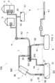
- the water distribution system (100) comprises a supply conduit (1) for the passage of water (A1) coming from an urban waterworks.
- said supply conduit (1) is an integral part of a water system that connects different neighborhoods or residential areas.
- the water distribution system (100) also comprises a purification and filtration unit (2) connected to the supply conduit (1) and suitable for purifying and filtering the water (A1) coming from the supply conduit (1).
- the temperature (T1) of the water (A1) coming from the urban waterworks usually depends on the outdoor environmental conditions.
- the purification/filtration unit (2) is provided with means configured for filtering and purifying the water (A1), eliminating the scale that is deposited inside the supply conduit (1) with the passing of time.
- the water distribution system (100) comprises a thermal power plant (3) configured to produce hot water (A2) at a first temperature (T2) by heating the water (A1) supplied from the waterworks.
- the thermal power plant (3) receives the water (A1) coming from the purification and filtration unit (2) that is arranged upstream of the thermal power plant (3).
- the temperature (T2) of the hot water (A2) is comprised between 96°C and 99°C and is higher than the temperature (T1) of the water (A1) coming from the waterworks.
- the water distribution system (100) also comprises a plurality of utilities (U) arranged to receive the hot water (A2) produced by and coming from the thermal power plant (3). Therefore, hot water (A2) is constantly received in the utilities (U).
- utilities indicates any building or facility for residential, industrial or similar use.
- a water distribution network (7) connects said thermal power plant (3) to said plurality of utilities (U).
- Said water distribution network (7) may coincide with the distribution water network that is used in the prior art to conventionally supply the cold water from the urban waterworks to the individual utilities (U). Otherwise said, the water distribution network (7) may coincide with the pre-existing water network of the urban area.
- the water distribution network (7) comprises pipes and a pumping system (P) configured to pump the hot water (A2) from the thermal power plant (3) to the utilities (U).
- P pumping system
- each utility (U) comprises an internal water system (8) provided with dispensing terminals (81).
- said dispensing terminals (81) comprise a sink faucet, a shower faucet, an inlet pipe of a household appliance (e.g., a washing machine or a dishwasher), and any other water terminal from which water is intended to flow.
- the dispensing terminals may also comprise mixers or valves to regulate the temperature of the water coming out of such dispensing terminals (81).
- the internal water system (8) comprises a cooling tank (80) that is arranged to be supplied with the hot water (A2) coming from the water distribution network (7).
- the cooling tank (80) is also arranged to deliver cold water (A3) at a second temperature (T3) that is lower than the first temperature (T2) of hot water (A2).
- the internal water system (8) also comprises two separate water distribution networks (83, 84) to distribute the water to the dispensing terminals (81).
- a hot-water distribution network (84) that is directly supplied with the hot water (A2) coming from the water distribution network (7), and a cold-water distribution network (83) that is supplied with the cold water (A3) delivered from the cooling tank (80) can be distinguished.
- the dispensing terminal (81) receives cold water (A3) (passing through the cold-water distribution network (83)) and hot water (A2) (passing through the hot-water distribution network (84)). At this point a user can adjust the temperature of the water coming out of the dispensing terminal (81) by simply operating the mixer or the valve of the dispensing terminal (81).
- the cooling of the water inside the cooling tank (80) occurs by heat transfer from the inside to the outside the cooling tank (80). Otherwise said, the hot water (A2) introduced in the cooling tank (80) is gradually cooled until it reaches a thermal equilibrium with the outdoor environment in which the cooling tank (80) is installed, and is converted into cold water (A3).
- cooling means may be provided inside the cooling tank (80) and configured to cool the water inside the cooling tank (80) so as to accelerate the water cooling process.
- a temperature sensor (88) may be provided inside the cooling tank (80) and configured to detect the temperature of the water stored inside the cooling tank (80).
- a valve (89) may be provided between the cooling tank (80) and the cold-water distribution network (83) and interfaced with said temperature sensor (88) in such a way to be alternately disposed in:
- the valve (89) is arranged in open position when the temperature sensor (88) detects that the cooled water inside the cooling tank (80) has a temperature lower than a preset temperature. Conversely, the valve (89) is arranged in closed position when the temperature sensor (88) detects that the cooled water inside the cooling tank (80) has a temperature higher than a preset temperature.
- the cold-water distribution network (83) will be always filled with cold water (A3), that is to say, with water having a temperature (T3) lower than a preset temperature.
- each utility (U) may comprise a heating system (82) of the indoor environment of the utility (U) comprising heat exchangers (820) (such as radiators or coils).
- heat exchangers (820) such as radiators or coils.
- the heating system (82) is arranged upstream of the water distribution networks (83, 84) and the heat exchangers (820) are arranged for the passage of the hot water (A2) coming from the water distribution network (7). Then, the hot water (A2) delivered from said heat exchangers (820) is supplied into the hot-water distribution network (84) and in the cooling tank (80). Otherwise said, the hot water (A2) introduced into the internal water system (8) will first pass through the heat exchangers (820) of the heating system (82) and will then flow toward the hot-water distribution network (84) and toward the cooling tank (80). Obviously, the hot water (A2) coming from the heating system (82) will have a lower temperature than the hot water (A2) entering the heating system (82) because part of the heat will be transferred to the outdoor environment via the heat exchangers (820).
- the heating system (82) comprises a valve assembly (V) configured to prevent or allow the passage of hot water (A2) inside the heat exchangers (820) of the heating system (82). Otherwise said, the valve assembly (V) allows the hot water (A2) (coming from the water distribution system (7)) to by-pass or not the heat exchangers (820).
- V valve assembly
- said thermal power plant (3) uses renewable sources to heat the water.
- the thermal power plant (3) is powered by solar energy.
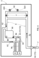
- the thermal power plant (3) comprises a heat exchanger (30) of "water-heat transfer fluid" type.
- the heat exchanger (30) comprises first pipes (301) for the passage of water (A1, A2) and second pipes (302) for the passage of a heat transfer fluid (L).
- the heat transfer fluid (L) is preferably a diathermic oil.
- the first pipes (301) and the second pipes (302) are in thermal communication with each other so that a heat exchange occurs between the heat transfer fluid (L) flowing through the second pipes (302) and the water (A1, A2) flowing through the first pipes (301).
- the water (A1, A2) acquires the heat from the heat transfer fluid (L) so that the water (A1) (coming from the urban waterworks) becomes hot water (A2).
- the thermal power plant (3) also comprises a heat transfer fluid tank (31) in which the heat transfer fluid (L) is stored.
- Delivery pipes (33) and return pipes (34) are provided to hydraulically connect the heat transfer fluid tank (31) with the second pipes (302) of the heat exchanger (30).
- a pump (35) is configured to draw the heat transfer fluid (L) from the heat transfer fluid tank (31), let the heat transfer fluid (L) flow inside the delivery pipes (33), then inside the second pipes (302), and finally inside the return pipes (34) so that the heat transfer fluid (L) flows back inside the heat transfer fluid tank (31).
- Means (36) are arranged at the delivery pipes (33) to transfer the heat to the heat transfer fluid (L) passing through the delivery pipes (33).
- Said means (36) preferably comprise an optical solar concentration system (360) configured to concentrate the sunlight in one or more focal points on the delivery pipes (33) so that the heat transfer fluid (L) absorbs solar energy and is heated.
- an optical solar concentration system 360
- the heat transfer fluid L
- said optical solar concentration system (360) comprises parabolic mirrors or linear mirrors with Fresnel reflectors or circular parabolic reflectors and the like.
- the thermal power plant (3) comprises a heat transfer fluid temperature conditioning unit (G3) configured to maintain the heat transfer fluid (L) at a preset operating temperature.
- G3 heat transfer fluid temperature conditioning unit
- the heat transfer fluid temperature conditioning unit (G3) comprises:
- said heat transfer fluid temperature conditioning unit (G3) allows to constantly maintain the heat transfer fluid (L) at the operating temperature during a prolonged absence of the sunlight and during night hours.
- the heat transfer fluid tank (31) is buried, i.e., placed under the ground (T) in such a way to limit the heat loss.
- a water storage tank (6) is provided in adjacent position to the heat transfer fluid tank (31) and is hydraulically connected to the purification and filtration unit (2), to the water distribution network (7) and to the thermal power plant (3).
- said water storage tank (6) is connected to the first pipes (301) of the heat exchanger (30) by means of a first pipe (51) and of a second pipe (52) that define a closed water recirculation circuit between the heat exchanger (30) and the water storage tank (6).
- the water storage tank (6) comprises a pump (53) configured to draw the water from the water storage tank (6) and pump it inside the first pipes (301) of the heat exchanger (30) so that the water is heated and is then reintroduced into the water storage tank (6).
- the water distribution network (7) is directly connected to the water storage tank (6), and the pumping system (P) of the water distribution network (7) draws the water directly from the water storage tank (6).
- the water storage tank (6) will always contain hot water (A2), preferably at a temperature (T2) comprised between 96°C and 99°C.
- said water storage tank (6) is connected to the first pipes (301) of the heat exchanger (30) by the means of a single pipe (50).
- the water distribution network (7) is directly connected to the first pipes (301) of the heat exchanger (30), and the pumping system (P) is configured to draw the water from the water storage tank (6), letting it pass through the first pipes (301) of the heat exchanger (30) (so that the water is heated) and then into the water distribution network (7).
- a plurality of auxiliary heating units (4) may be provided along the water distribution network (7).
- said auxiliary heating units (4) comprise:
- the function of the auxiliary heating unit or units (4) is to constantly maintain the hot water (A2) circulating in the water distribution system (7) at a temperature comprised between 96°C and 99°C.
- the sensor (42) and the electric heating element (43) of the auxiliary heating unit (4) may be powered by the electric current generated by photovoltaic panels that are already installed or may be installed on the buildings of the utilities (U).
- the internal water systems (8) of the utilities (U) are all supplied by a single water distribution network (7) that provides hot water (A2), and therefore the conventional boilers that discharge polluting gases into the environment can be eliminated.
- the water distribution system (100) according to the present invention can be easily adapted to the existing water supply networks with boilers without having to revolutionize the structural arrangement of the networks that are currently present in neighborhoods, municipalities and cities.
- the pre-existing urban water distribution network that until now is used to supply cold water to the utilities (U) can be used as water distribution network (7).
- thermal power plant (3) may comprise biomass plants or other plants that use renewable energy to heat the water.
Landscapes
- Engineering & Computer Science (AREA)
- Physics & Mathematics (AREA)
- Thermal Sciences (AREA)
- Chemical & Material Sciences (AREA)
- Combustion & Propulsion (AREA)
- Mechanical Engineering (AREA)
- General Engineering & Computer Science (AREA)
- Fluid Mechanics (AREA)
- Heat-Pump Type And Storage Water Heaters (AREA)
Applications Claiming Priority (1)
| Application Number | Priority Date | Filing Date | Title |
|---|---|---|---|
| IT202300010686 | 2023-05-26 |
Publications (1)
| Publication Number | Publication Date |
|---|---|
| EP4467883A1 true EP4467883A1 (de) | 2024-11-27 |
Family
ID=87800993
Family Applications (1)
| Application Number | Title | Priority Date | Filing Date |
|---|---|---|---|
| EP24174474.7A Withdrawn EP4467883A1 (de) | 2023-05-26 | 2024-05-07 | Warmwassersystem zur verteilung an mehrere städtische einrichtungen |
Country Status (1)
| Country | Link |
|---|---|
| EP (1) | EP4467883A1 (de) |
Citations (4)
| Publication number | Priority date | Publication date | Assignee | Title |
|---|---|---|---|---|
| BE826612A (fr) * | 1975-03-12 | 1975-06-30 | Groupe individuel de chauffage par eau chaude pour immeuble a appartements | |
| DE2518161B1 (de) * | 1975-04-16 | 1976-10-28 | Sulzer Ag | Heizkraftwerk mit fernheizanlage |
| GB2076524A (en) | 1980-05-23 | 1981-12-02 | Bell George Malcolm | District Heating |
| DE102008019186A1 (de) * | 2008-04-17 | 2009-11-05 | Robert Bosch Gmbh | Verfahren und Vorrichtung zur dezentralen Warmwasserbereitung |
-
2024
- 2024-05-07 EP EP24174474.7A patent/EP4467883A1/de not_active Withdrawn
Patent Citations (4)
| Publication number | Priority date | Publication date | Assignee | Title |
|---|---|---|---|---|
| BE826612A (fr) * | 1975-03-12 | 1975-06-30 | Groupe individuel de chauffage par eau chaude pour immeuble a appartements | |
| DE2518161B1 (de) * | 1975-04-16 | 1976-10-28 | Sulzer Ag | Heizkraftwerk mit fernheizanlage |
| GB2076524A (en) | 1980-05-23 | 1981-12-02 | Bell George Malcolm | District Heating |
| DE102008019186A1 (de) * | 2008-04-17 | 2009-11-05 | Robert Bosch Gmbh | Verfahren und Vorrichtung zur dezentralen Warmwasserbereitung |
Similar Documents
| Publication | Publication Date | Title |
|---|---|---|
| AU2010262686B2 (en) | District energy sharing system | |
| EP2438358B1 (de) | Heizsystem | |
| CA2901700C (en) | Systems and methods for recovering energy from wastewater | |
| BG3459U1 (bg) | Комбинирана система за подгряване на вода и отоплителна течност за битово отопление | |
| EP4467883A1 (de) | Warmwassersystem zur verteilung an mehrere städtische einrichtungen | |
| EP3732400B1 (de) | Verfahren zur verbesserten nutzung von stromnetzen | |
| US20110272132A1 (en) | Arrangement and method for heating drinking water for one consumption point or tapping point | |
| WO2005119014A1 (en) | Remote-heating plant for urban, civil, industrial and agricultural applications | |
| RU2020383C1 (ru) | Способ теплоснабжения | |
| RU2160872C1 (ru) | Способ теплоснабжения городских потребителей от загородной тэц и система теплоснабжения | |
| CN204574619U (zh) | 一种带辅助加热设备的澡堂废水再利用系统 | |
| CN205014605U (zh) | 多功能数控高频电磁热水器 | |
| WO2011073921A2 (en) | Split system for heating and storing water for solar heating plants, and relative method to control operation of the system | |
| RU2023959C1 (ru) | Тепловой пункт системы теплоснабжения | |
| RU1815519C (ru) | Способ теплоснабжени по методу Г.С.Рузавина и система теплоснабжени | |
| SU1606818A1 (ru) | Тепловой пункт | |
| CN101634491B (zh) | 太阳能、油气同步或交替及余热应用的热水系统和方法 | |
| RU2044223C1 (ru) | Способ теплоснабжения | |
| CZ9801682A3 (cs) | Zapojení pro vytápění zejména obytných budov a pro přípravu teplé užitkové vody | |
| RU1772530C (ru) | Автономна система гор чего водоснабжени | |
| Li et al. | Technological issues to supply low temperature district heating | |
| RU2571361C1 (ru) | Система централизованного теплоснабжения, горячего и холодного водоснабжения | |
| RU13049U1 (ru) | Система теплоснабжения многоэтажного здания | |
| CZ2010672A3 (cs) | Zarízení pro ohrev teplé vody, zvlášte v objektech s centrálním rozvodem teplé vody | |
| EA005703B1 (ru) | Способ и система теплоснабжения и горячего водоснабжения |
Legal Events
| Date | Code | Title | Description |
|---|---|---|---|
| PUAI | Public reference made under article 153(3) epc to a published international application that has entered the european phase |
Free format text: ORIGINAL CODE: 0009012 |
|
| STAA | Information on the status of an ep patent application or granted ep patent |
Free format text: STATUS: THE APPLICATION HAS BEEN PUBLISHED |
|
| AK | Designated contracting states |
Kind code of ref document: A1 Designated state(s): AL AT BE BG CH CY CZ DE DK EE ES FI FR GB GR HR HU IE IS IT LI LT LU LV MC ME MK MT NL NO PL PT RO RS SE SI SK SM TR |
|
| STAA | Information on the status of an ep patent application or granted ep patent |
Free format text: STATUS: THE APPLICATION IS DEEMED TO BE WITHDRAWN |
|
| 18D | Application deemed to be withdrawn |
Effective date: 20250528 |