EP4468135A1 - Tragbare vorrichtung und elektronische vorrichtung zur bereitstellung von feedback an einen benutzer - Google Patents
Tragbare vorrichtung und elektronische vorrichtung zur bereitstellung von feedback an einen benutzer Download PDFInfo
- Publication number
- EP4468135A1 EP4468135A1 EP23827534.1A EP23827534A EP4468135A1 EP 4468135 A1 EP4468135 A1 EP 4468135A1 EP 23827534 A EP23827534 A EP 23827534A EP 4468135 A1 EP4468135 A1 EP 4468135A1
- Authority
- EP
- European Patent Office
- Prior art keywords
- user
- wearable device
- display
- state
- exercise
- Prior art date
- Legal status (The legal status is an assumption and is not a legal conclusion. Google has not performed a legal analysis and makes no representation as to the accuracy of the status listed.)
- Pending
Links
Images



























Classifications
-
- G—PHYSICS
- G06—COMPUTING OR CALCULATING; COUNTING
- G06F—ELECTRIC DIGITAL DATA PROCESSING
- G06F3/00—Input arrangements for transferring data to be processed into a form capable of being handled by the computer; Output arrangements for transferring data from processing unit to output unit, e.g. interface arrangements
- G06F3/01—Input arrangements or combined input and output arrangements for interaction between user and computer
- G06F3/048—Interaction techniques based on graphical user interfaces [GUI]
- G06F3/0484—Interaction techniques based on graphical user interfaces [GUI] for the control of specific functions or operations, e.g. selecting or manipulating an object, an image or a displayed text element, setting a parameter value or selecting a range
- G06F3/04842—Selection of displayed objects or displayed text elements
-
- A—HUMAN NECESSITIES
- A63—SPORTS; GAMES; AMUSEMENTS
- A63B—APPARATUS FOR PHYSICAL TRAINING, GYMNASTICS, SWIMMING, CLIMBING, OR FENCING; BALL GAMES; TRAINING EQUIPMENT
- A63B24/00—Electric or electronic controls for exercising apparatus of preceding groups; Controlling or monitoring of exercises, sportive games, training or athletic performances
- A63B24/0062—Monitoring athletic performances, e.g. for determining the work of a user on an exercise apparatus, the completed jogging or cycling distance
-
- A—HUMAN NECESSITIES
- A61—MEDICAL OR VETERINARY SCIENCE; HYGIENE
- A61B—DIAGNOSIS; SURGERY; IDENTIFICATION
- A61B5/00—Measuring for diagnostic purposes; Identification of persons
- A61B5/103—Measuring devices for testing the shape, pattern, colour, size or movement of the body or parts thereof, for diagnostic purposes
- A61B5/11—Measuring movement of the entire body or parts thereof, e.g. head or hand tremor or mobility of a limb
-
- A—HUMAN NECESSITIES
- A61—MEDICAL OR VETERINARY SCIENCE; HYGIENE
- A61B—DIAGNOSIS; SURGERY; IDENTIFICATION
- A61B5/00—Measuring for diagnostic purposes; Identification of persons
- A61B5/68—Arrangements of detecting, measuring or recording means, e.g. sensors, in relation to patient
- A61B5/6801—Arrangements of detecting, measuring or recording means, e.g. sensors, in relation to patient specially adapted to be attached to or worn on the body surface
- A61B5/6802—Sensor mounted on worn items
-
- A—HUMAN NECESSITIES
- A61—MEDICAL OR VETERINARY SCIENCE; HYGIENE
- A61B—DIAGNOSIS; SURGERY; IDENTIFICATION
- A61B5/00—Measuring for diagnostic purposes; Identification of persons
- A61B5/74—Details of notification to user or communication with user or patient; User input means
- A61B5/742—Details of notification to user or communication with user or patient; User input means using visual displays
- A61B5/7435—Displaying user selection data, e.g. icons in a graphical user interface
-
- A—HUMAN NECESSITIES
- A61—MEDICAL OR VETERINARY SCIENCE; HYGIENE
- A61B—DIAGNOSIS; SURGERY; IDENTIFICATION
- A61B5/00—Measuring for diagnostic purposes; Identification of persons
- A61B5/74—Details of notification to user or communication with user or patient; User input means
- A61B5/742—Details of notification to user or communication with user or patient; User input means using visual displays
- A61B5/744—Displaying an avatar, e.g. an animated cartoon character
-
- A—HUMAN NECESSITIES
- A61—MEDICAL OR VETERINARY SCIENCE; HYGIENE
- A61H—PHYSICAL THERAPY APPARATUS, e.g. DEVICES FOR LOCATING OR STIMULATING REFLEX POINTS IN THE BODY; ARTIFICIAL RESPIRATION; MASSAGE; BATHING DEVICES FOR SPECIAL THERAPEUTIC OR HYGIENIC PURPOSES OR SPECIFIC PARTS OF THE BODY
- A61H1/00—Apparatus for passive exercising; Vibrating apparatus; Chiropractic devices, e.g. body impacting devices, external devices for briefly extending or aligning unbroken bones
- A61H1/02—Stretching or bending or torsioning apparatus for exercising
- A61H1/0237—Stretching or bending or torsioning apparatus for exercising for the lower limbs
- A61H1/0244—Hip
-
- A—HUMAN NECESSITIES
- A61—MEDICAL OR VETERINARY SCIENCE; HYGIENE
- A61H—PHYSICAL THERAPY APPARATUS, e.g. DEVICES FOR LOCATING OR STIMULATING REFLEX POINTS IN THE BODY; ARTIFICIAL RESPIRATION; MASSAGE; BATHING DEVICES FOR SPECIAL THERAPEUTIC OR HYGIENIC PURPOSES OR SPECIFIC PARTS OF THE BODY
- A61H3/00—Appliances for aiding patients or disabled persons to walk about
-
- A—HUMAN NECESSITIES
- A63—SPORTS; GAMES; AMUSEMENTS
- A63B—APPARATUS FOR PHYSICAL TRAINING, GYMNASTICS, SWIMMING, CLIMBING, OR FENCING; BALL GAMES; TRAINING EQUIPMENT
- A63B21/00—Exercising apparatus for developing or strengthening the muscles or joints of the body by working against a counterforce, with or without measuring devices
- A63B21/00178—Exercising apparatus for developing or strengthening the muscles or joints of the body by working against a counterforce, with or without measuring devices for active exercising, the apparatus being also usable for passive exercising
-
- A—HUMAN NECESSITIES
- A63—SPORTS; GAMES; AMUSEMENTS
- A63B—APPARATUS FOR PHYSICAL TRAINING, GYMNASTICS, SWIMMING, CLIMBING, OR FENCING; BALL GAMES; TRAINING EQUIPMENT
- A63B21/00—Exercising apparatus for developing or strengthening the muscles or joints of the body by working against a counterforce, with or without measuring devices
- A63B21/00181—Exercising apparatus for developing or strengthening the muscles or joints of the body by working against a counterforce, with or without measuring devices comprising additional means assisting the user to overcome part of the resisting force, i.e. assisted-active exercising
-
- A—HUMAN NECESSITIES
- A63—SPORTS; GAMES; AMUSEMENTS
- A63B—APPARATUS FOR PHYSICAL TRAINING, GYMNASTICS, SWIMMING, CLIMBING, OR FENCING; BALL GAMES; TRAINING EQUIPMENT
- A63B21/00—Exercising apparatus for developing or strengthening the muscles or joints of the body by working against a counterforce, with or without measuring devices
- A63B21/40—Interfaces with the user related to strength training; Details thereof
- A63B21/4001—Arrangements for attaching the exercising apparatus to the user's body, e.g. belts, shoes or gloves specially adapted therefor
- A63B21/4009—Arrangements for attaching the exercising apparatus to the user's body, e.g. belts, shoes or gloves specially adapted therefor to the waist
-
- A—HUMAN NECESSITIES
- A63—SPORTS; GAMES; AMUSEMENTS
- A63B—APPARATUS FOR PHYSICAL TRAINING, GYMNASTICS, SWIMMING, CLIMBING, OR FENCING; BALL GAMES; TRAINING EQUIPMENT
- A63B21/00—Exercising apparatus for developing or strengthening the muscles or joints of the body by working against a counterforce, with or without measuring devices
- A63B21/40—Interfaces with the user related to strength training; Details thereof
- A63B21/4001—Arrangements for attaching the exercising apparatus to the user's body, e.g. belts, shoes or gloves specially adapted therefor
- A63B21/4011—Arrangements for attaching the exercising apparatus to the user's body, e.g. belts, shoes or gloves specially adapted therefor to the lower limbs
-
- A—HUMAN NECESSITIES
- A63—SPORTS; GAMES; AMUSEMENTS
- A63B—APPARATUS FOR PHYSICAL TRAINING, GYMNASTICS, SWIMMING, CLIMBING, OR FENCING; BALL GAMES; TRAINING EQUIPMENT
- A63B21/00—Exercising apparatus for developing or strengthening the muscles or joints of the body by working against a counterforce, with or without measuring devices
- A63B21/40—Interfaces with the user related to strength training; Details thereof
- A63B21/4023—Interfaces with the user related to strength training; Details thereof the user operating the resistance directly, without additional interface
- A63B21/4025—Resistance devices worn on the user's body
-
- A—HUMAN NECESSITIES
- A63—SPORTS; GAMES; AMUSEMENTS
- A63B—APPARATUS FOR PHYSICAL TRAINING, GYMNASTICS, SWIMMING, CLIMBING, OR FENCING; BALL GAMES; TRAINING EQUIPMENT
- A63B23/00—Exercising apparatus specially adapted for particular parts of the body
- A63B23/035—Exercising apparatus specially adapted for particular parts of the body for limbs, i.e. upper or lower limbs, e.g. simultaneously
- A63B23/04—Exercising apparatus specially adapted for particular parts of the body for limbs, i.e. upper or lower limbs, e.g. simultaneously for lower limbs
- A63B23/0482—Exercising apparatus specially adapted for particular parts of the body for limbs, i.e. upper or lower limbs, e.g. simultaneously for lower limbs primarily by articulating the hip joints
-
- A—HUMAN NECESSITIES
- A63—SPORTS; GAMES; AMUSEMENTS
- A63B—APPARATUS FOR PHYSICAL TRAINING, GYMNASTICS, SWIMMING, CLIMBING, OR FENCING; BALL GAMES; TRAINING EQUIPMENT
- A63B24/00—Electric or electronic controls for exercising apparatus of preceding groups; Controlling or monitoring of exercises, sportive games, training or athletic performances
- A63B24/0087—Electric or electronic controls for exercising apparatus of groups A63B21/00 - A63B23/00, e.g. controlling load
-
- A—HUMAN NECESSITIES
- A63—SPORTS; GAMES; AMUSEMENTS
- A63B—APPARATUS FOR PHYSICAL TRAINING, GYMNASTICS, SWIMMING, CLIMBING, OR FENCING; BALL GAMES; TRAINING EQUIPMENT
- A63B71/00—Games or sports accessories not covered in groups A63B1/00 - A63B69/00
- A63B71/06—Indicating or scoring devices for games or players, or for other sports activities
- A63B71/0619—Displays, user interfaces and indicating devices, specially adapted for sport equipment, e.g. display mounted on treadmills
- A63B71/0622—Visual, audio or audio-visual systems for entertaining, instructing or motivating the user
-
- G—PHYSICS
- G06—COMPUTING OR CALCULATING; COUNTING
- G06F—ELECTRIC DIGITAL DATA PROCESSING
- G06F1/00—Details not covered by groups G06F3/00 - G06F13/00 and G06F21/00
- G06F1/16—Constructional details or arrangements
- G06F1/1613—Constructional details or arrangements for portable computers
- G06F1/163—Wearable computers, e.g. on a belt
-
- G—PHYSICS
- G06—COMPUTING OR CALCULATING; COUNTING
- G06F—ELECTRIC DIGITAL DATA PROCESSING
- G06F1/00—Details not covered by groups G06F3/00 - G06F13/00 and G06F21/00
- G06F1/16—Constructional details or arrangements
- G06F1/1613—Constructional details or arrangements for portable computers
- G06F1/1633—Constructional details or arrangements of portable computers not specific to the type of enclosures covered by groups G06F1/1615 - G06F1/1626
- G06F1/1684—Constructional details or arrangements related to integrated I/O peripherals not covered by groups G06F1/1635 - G06F1/1675
- G06F1/1694—Constructional details or arrangements related to integrated I/O peripherals not covered by groups G06F1/1635 - G06F1/1675 the I/O peripheral being a single or a set of motion sensors for pointer control or gesture input obtained by sensing movements of the portable computer
-
- G—PHYSICS
- G06—COMPUTING OR CALCULATING; COUNTING
- G06F—ELECTRIC DIGITAL DATA PROCESSING
- G06F3/00—Input arrangements for transferring data to be processed into a form capable of being handled by the computer; Output arrangements for transferring data from processing unit to output unit, e.g. interface arrangements
- G06F3/01—Input arrangements or combined input and output arrangements for interaction between user and computer
- G06F3/016—Input arrangements with force or tactile feedback as computer generated output to the user
-
- G—PHYSICS
- G06—COMPUTING OR CALCULATING; COUNTING
- G06F—ELECTRIC DIGITAL DATA PROCESSING
- G06F3/00—Input arrangements for transferring data to be processed into a form capable of being handled by the computer; Output arrangements for transferring data from processing unit to output unit, e.g. interface arrangements
- G06F3/01—Input arrangements or combined input and output arrangements for interaction between user and computer
- G06F3/048—Interaction techniques based on graphical user interfaces [GUI]
- G06F3/0481—Interaction techniques based on graphical user interfaces [GUI] based on specific properties of the displayed interaction object or a metaphor-based environment, e.g. interaction with desktop elements like windows or icons, or assisted by a cursor's changing behaviour or appearance
-
- G—PHYSICS
- G06—COMPUTING OR CALCULATING; COUNTING
- G06F—ELECTRIC DIGITAL DATA PROCESSING
- G06F3/00—Input arrangements for transferring data to be processed into a form capable of being handled by the computer; Output arrangements for transferring data from processing unit to output unit, e.g. interface arrangements
- G06F3/16—Sound input; Sound output
-
- G—PHYSICS
- G06—COMPUTING OR CALCULATING; COUNTING
- G06Q—INFORMATION AND COMMUNICATION TECHNOLOGY [ICT] SPECIALLY ADAPTED FOR ADMINISTRATIVE, COMMERCIAL, FINANCIAL, MANAGERIAL OR SUPERVISORY PURPOSES; SYSTEMS OR METHODS SPECIALLY ADAPTED FOR ADMINISTRATIVE, COMMERCIAL, FINANCIAL, MANAGERIAL OR SUPERVISORY PURPOSES, NOT OTHERWISE PROVIDED FOR
- G06Q50/00—Information and communication technology [ICT] specially adapted for implementation of business processes of specific business sectors, e.g. utilities or tourism
- G06Q50/10—Services
-
- H—ELECTRICITY
- H04—ELECTRIC COMMUNICATION TECHNIQUE
- H04W—WIRELESS COMMUNICATION NETWORKS
- H04W4/00—Services specially adapted for wireless communication networks; Facilities therefor
- H04W4/80—Services using short range communication, e.g. near-field communication [NFC], radio-frequency identification [RFID] or low energy communication
-
- A—HUMAN NECESSITIES
- A61—MEDICAL OR VETERINARY SCIENCE; HYGIENE
- A61H—PHYSICAL THERAPY APPARATUS, e.g. DEVICES FOR LOCATING OR STIMULATING REFLEX POINTS IN THE BODY; ARTIFICIAL RESPIRATION; MASSAGE; BATHING DEVICES FOR SPECIAL THERAPEUTIC OR HYGIENIC PURPOSES OR SPECIFIC PARTS OF THE BODY
- A61H2201/00—Characteristics of apparatus not provided for in the preceding codes
- A61H2201/16—Physical interface with patient
- A61H2201/1602—Physical interface with patient kind of interface, e.g. head rest, knee support or lumbar support
- A61H2201/1628—Pelvis
-
- A—HUMAN NECESSITIES
- A61—MEDICAL OR VETERINARY SCIENCE; HYGIENE
- A61H—PHYSICAL THERAPY APPARATUS, e.g. DEVICES FOR LOCATING OR STIMULATING REFLEX POINTS IN THE BODY; ARTIFICIAL RESPIRATION; MASSAGE; BATHING DEVICES FOR SPECIAL THERAPEUTIC OR HYGIENIC PURPOSES OR SPECIFIC PARTS OF THE BODY
- A61H2201/00—Characteristics of apparatus not provided for in the preceding codes
- A61H2201/16—Physical interface with patient
- A61H2201/1602—Physical interface with patient kind of interface, e.g. head rest, knee support or lumbar support
- A61H2201/164—Feet or leg, e.g. pedal
-
- A—HUMAN NECESSITIES
- A61—MEDICAL OR VETERINARY SCIENCE; HYGIENE
- A61H—PHYSICAL THERAPY APPARATUS, e.g. DEVICES FOR LOCATING OR STIMULATING REFLEX POINTS IN THE BODY; ARTIFICIAL RESPIRATION; MASSAGE; BATHING DEVICES FOR SPECIAL THERAPEUTIC OR HYGIENIC PURPOSES OR SPECIFIC PARTS OF THE BODY
- A61H2201/00—Characteristics of apparatus not provided for in the preceding codes
- A61H2201/16—Physical interface with patient
- A61H2201/1602—Physical interface with patient kind of interface, e.g. head rest, knee support or lumbar support
- A61H2201/165—Wearable interfaces
-
- A—HUMAN NECESSITIES
- A61—MEDICAL OR VETERINARY SCIENCE; HYGIENE
- A61H—PHYSICAL THERAPY APPARATUS, e.g. DEVICES FOR LOCATING OR STIMULATING REFLEX POINTS IN THE BODY; ARTIFICIAL RESPIRATION; MASSAGE; BATHING DEVICES FOR SPECIAL THERAPEUTIC OR HYGIENIC PURPOSES OR SPECIFIC PARTS OF THE BODY
- A61H2201/00—Characteristics of apparatus not provided for in the preceding codes
- A61H2201/50—Control means thereof
- A61H2201/5007—Control means thereof computer controlled
-
- A—HUMAN NECESSITIES
- A61—MEDICAL OR VETERINARY SCIENCE; HYGIENE
- A61H—PHYSICAL THERAPY APPARATUS, e.g. DEVICES FOR LOCATING OR STIMULATING REFLEX POINTS IN THE BODY; ARTIFICIAL RESPIRATION; MASSAGE; BATHING DEVICES FOR SPECIAL THERAPEUTIC OR HYGIENIC PURPOSES OR SPECIFIC PARTS OF THE BODY
- A61H2201/00—Characteristics of apparatus not provided for in the preceding codes
- A61H2201/50—Control means thereof
- A61H2201/5023—Interfaces to the user
- A61H2201/5035—Several programs selectable
-
- A—HUMAN NECESSITIES
- A61—MEDICAL OR VETERINARY SCIENCE; HYGIENE
- A61H—PHYSICAL THERAPY APPARATUS, e.g. DEVICES FOR LOCATING OR STIMULATING REFLEX POINTS IN THE BODY; ARTIFICIAL RESPIRATION; MASSAGE; BATHING DEVICES FOR SPECIAL THERAPEUTIC OR HYGIENIC PURPOSES OR SPECIFIC PARTS OF THE BODY
- A61H2201/00—Characteristics of apparatus not provided for in the preceding codes
- A61H2201/50—Control means thereof
- A61H2201/5023—Interfaces to the user
- A61H2201/5043—Displays
- A61H2201/5046—Touch screens
-
- A—HUMAN NECESSITIES
- A61—MEDICAL OR VETERINARY SCIENCE; HYGIENE
- A61H—PHYSICAL THERAPY APPARATUS, e.g. DEVICES FOR LOCATING OR STIMULATING REFLEX POINTS IN THE BODY; ARTIFICIAL RESPIRATION; MASSAGE; BATHING DEVICES FOR SPECIAL THERAPEUTIC OR HYGIENIC PURPOSES OR SPECIFIC PARTS OF THE BODY
- A61H2201/00—Characteristics of apparatus not provided for in the preceding codes
- A61H2201/50—Control means thereof
- A61H2201/5058—Sensors or detectors
- A61H2201/5084—Acceleration sensors
-
- A—HUMAN NECESSITIES
- A63—SPORTS; GAMES; AMUSEMENTS
- A63B—APPARATUS FOR PHYSICAL TRAINING, GYMNASTICS, SWIMMING, CLIMBING, OR FENCING; BALL GAMES; TRAINING EQUIPMENT
- A63B22/00—Exercising apparatus specially adapted for conditioning the cardio-vascular system, for training agility or co-ordination of movements
- A63B2022/0092—Exercising apparatus specially adapted for conditioning the cardio-vascular system, for training agility or co-ordination of movements for training agility or co-ordination of movements
-
- A—HUMAN NECESSITIES
- A63—SPORTS; GAMES; AMUSEMENTS
- A63B—APPARATUS FOR PHYSICAL TRAINING, GYMNASTICS, SWIMMING, CLIMBING, OR FENCING; BALL GAMES; TRAINING EQUIPMENT
- A63B22/00—Exercising apparatus specially adapted for conditioning the cardio-vascular system, for training agility or co-ordination of movements
- A63B2022/0094—Exercising apparatus specially adapted for conditioning the cardio-vascular system, for training agility or co-ordination of movements for active rehabilitation, e.g. slow motion devices
-
- A—HUMAN NECESSITIES
- A63—SPORTS; GAMES; AMUSEMENTS
- A63B—APPARATUS FOR PHYSICAL TRAINING, GYMNASTICS, SWIMMING, CLIMBING, OR FENCING; BALL GAMES; TRAINING EQUIPMENT
- A63B24/00—Electric or electronic controls for exercising apparatus of preceding groups; Controlling or monitoring of exercises, sportive games, training or athletic performances
- A63B24/0062—Monitoring athletic performances, e.g. for determining the work of a user on an exercise apparatus, the completed jogging or cycling distance
- A63B2024/0065—Evaluating the fitness, e.g. fitness level or fitness index
-
- A—HUMAN NECESSITIES
- A63—SPORTS; GAMES; AMUSEMENTS
- A63B—APPARATUS FOR PHYSICAL TRAINING, GYMNASTICS, SWIMMING, CLIMBING, OR FENCING; BALL GAMES; TRAINING EQUIPMENT
- A63B24/00—Electric or electronic controls for exercising apparatus of preceding groups; Controlling or monitoring of exercises, sportive games, training or athletic performances
- A63B24/0062—Monitoring athletic performances, e.g. for determining the work of a user on an exercise apparatus, the completed jogging or cycling distance
- A63B2024/0068—Comparison to target or threshold, previous performance or not real time comparison to other individuals
-
- A—HUMAN NECESSITIES
- A63—SPORTS; GAMES; AMUSEMENTS
- A63B—APPARATUS FOR PHYSICAL TRAINING, GYMNASTICS, SWIMMING, CLIMBING, OR FENCING; BALL GAMES; TRAINING EQUIPMENT
- A63B24/00—Electric or electronic controls for exercising apparatus of preceding groups; Controlling or monitoring of exercises, sportive games, training or athletic performances
- A63B24/0087—Electric or electronic controls for exercising apparatus of groups A63B21/00 - A63B23/00, e.g. controlling load
- A63B2024/0093—Electric or electronic controls for exercising apparatus of groups A63B21/00 - A63B23/00, e.g. controlling load the load of the exercise apparatus being controlled by performance parameters, e.g. distance or speed
-
- A—HUMAN NECESSITIES
- A63—SPORTS; GAMES; AMUSEMENTS
- A63B—APPARATUS FOR PHYSICAL TRAINING, GYMNASTICS, SWIMMING, CLIMBING, OR FENCING; BALL GAMES; TRAINING EQUIPMENT
- A63B71/00—Games or sports accessories not covered in groups A63B1/00 - A63B69/00
- A63B71/06—Indicating or scoring devices for games or players, or for other sports activities
- A63B71/0619—Displays, user interfaces and indicating devices, specially adapted for sport equipment, e.g. display mounted on treadmills
- A63B2071/0655—Tactile feedback
-
- A—HUMAN NECESSITIES
- A63—SPORTS; GAMES; AMUSEMENTS
- A63B—APPARATUS FOR PHYSICAL TRAINING, GYMNASTICS, SWIMMING, CLIMBING, OR FENCING; BALL GAMES; TRAINING EQUIPMENT
- A63B71/00—Games or sports accessories not covered in groups A63B1/00 - A63B69/00
- A63B71/06—Indicating or scoring devices for games or players, or for other sports activities
- A63B71/0619—Displays, user interfaces and indicating devices, specially adapted for sport equipment, e.g. display mounted on treadmills
- A63B2071/0658—Position or arrangement of display
- A63B2071/0661—Position or arrangement of display arranged on the user
- A63B2071/0663—Position or arrangement of display arranged on the user worn on the wrist, e.g. wrist bands
-
- A—HUMAN NECESSITIES
- A63—SPORTS; GAMES; AMUSEMENTS
- A63B—APPARATUS FOR PHYSICAL TRAINING, GYMNASTICS, SWIMMING, CLIMBING, OR FENCING; BALL GAMES; TRAINING EQUIPMENT
- A63B71/00—Games or sports accessories not covered in groups A63B1/00 - A63B69/00
- A63B71/06—Indicating or scoring devices for games or players, or for other sports activities
- A63B71/0619—Displays, user interfaces and indicating devices, specially adapted for sport equipment, e.g. display mounted on treadmills
- A63B2071/0658—Position or arrangement of display
- A63B2071/0661—Position or arrangement of display arranged on the user
- A63B2071/0666—Position or arrangement of display arranged on the user worn on the head or face, e.g. combined with goggles or glasses
-
- A—HUMAN NECESSITIES
- A63—SPORTS; GAMES; AMUSEMENTS
- A63B—APPARATUS FOR PHYSICAL TRAINING, GYMNASTICS, SWIMMING, CLIMBING, OR FENCING; BALL GAMES; TRAINING EQUIPMENT
- A63B21/00—Exercising apparatus for developing or strengthening the muscles or joints of the body by working against a counterforce, with or without measuring devices
- A63B21/40—Interfaces with the user related to strength training; Details thereof
- A63B21/4001—Arrangements for attaching the exercising apparatus to the user's body, e.g. belts, shoes or gloves specially adapted therefor
- A63B21/4017—Arrangements for attaching the exercising apparatus to the user's body, e.g. belts, shoes or gloves specially adapted therefor to the upper limbs
-
- A—HUMAN NECESSITIES
- A63—SPORTS; GAMES; AMUSEMENTS
- A63B—APPARATUS FOR PHYSICAL TRAINING, GYMNASTICS, SWIMMING, CLIMBING, OR FENCING; BALL GAMES; TRAINING EQUIPMENT
- A63B2220/00—Measuring of physical parameters relating to sporting activity
- A63B2220/40—Acceleration
-
- A—HUMAN NECESSITIES
- A63—SPORTS; GAMES; AMUSEMENTS
- A63B—APPARATUS FOR PHYSICAL TRAINING, GYMNASTICS, SWIMMING, CLIMBING, OR FENCING; BALL GAMES; TRAINING EQUIPMENT
- A63B2220/00—Measuring of physical parameters relating to sporting activity
- A63B2220/80—Special sensors, transducers or devices therefor
- A63B2220/805—Optical or opto-electronic sensors
-
- A—HUMAN NECESSITIES
- A63—SPORTS; GAMES; AMUSEMENTS
- A63B—APPARATUS FOR PHYSICAL TRAINING, GYMNASTICS, SWIMMING, CLIMBING, OR FENCING; BALL GAMES; TRAINING EQUIPMENT
- A63B2225/00—Miscellaneous features of sport apparatus, devices or equipment
- A63B2225/20—Miscellaneous features of sport apparatus, devices or equipment with means for remote communication, e.g. internet or the like
-
- A—HUMAN NECESSITIES
- A63—SPORTS; GAMES; AMUSEMENTS
- A63B—APPARATUS FOR PHYSICAL TRAINING, GYMNASTICS, SWIMMING, CLIMBING, OR FENCING; BALL GAMES; TRAINING EQUIPMENT
- A63B2225/00—Miscellaneous features of sport apparatus, devices or equipment
- A63B2225/50—Wireless data transmission, e.g. by radio transmitters or telemetry
Definitions
- Certain example embodiments relate to a wearable device and/or an electronic device for providing feedback to a user.
- a wearable device may help a user's exercise by applying an external force to the user.
- the wearable device may be paired with a user terminal (e.g., a smartphone), and may transmit data collected by the wearable device to the user terminal.
- a user terminal e.g., a smartphone
- a user wearing a wearable device may not easily determine a state of the wearable device during exercise.
- An example embodiment may provide an electronic device, and a wearable device configured to output feedback (e.g., at least one of visual feedback, auditory feedback, or haptic feedback) corresponding to a state of the wearable device to a user.
- feedback e.g., at least one of visual feedback, auditory feedback, or haptic feedback
- An electronic device may communicate with a wearable device that applies an external force to a user.
- the electronic device may include: a communication module, comprising communication circuitry, configured to establish a wireless communication link with the wearable device; a display; a memory configured to store a fitness application; and at least one processor configured to execute the fitness application and control the display to display a screen of the executed fitness application including a first area on the display.
- the at least one processor may be configured to receive first state information indicating that the wearable device is in a sensing state for sensing a motion of the user through the communication module, recognize a state of the wearable device as the sensing state according to the received first state information, and control the display to provide visual feedback corresponding to the sensing state through the first area.
- a wearable device may include a communication module, comprising communication circuitry, configured to establish a wireless communication link with an electronic device; a driving module, comprising a motor and/or circuitry, configured to generate torque to provide an external force to a user; a sensor configured to acquire motion information by sensing a motion of the user; a display module; and at least one processor configured to transmit first state information indicating that the wearable device is in a sensing state for sensing the motion to the electronic device through the communication module, control the display module to provide visual feedback corresponding to the sensing state through the display module, determine control information used for generating the torque by using at least some of the acquired motion information, and control the driving module to provide the external force to the user based on the determined control information.
- a communication module comprising communication circuitry, configured to establish a wireless communication link with an electronic device
- a driving module comprising a motor and/or circuitry, configured to generate torque to provide an external force to a user
- a sensor configured to acquire motion information by sensing a motion of
- a watch-type electronic device may communicate with a wearable device for applying an external force to a user.
- the watch-type electronic device may include: a communication module, comprising communication circuitry, configured to establish a wireless communication link with a user terminal and communicate with the wearable device through the user terminal; a display; a memory configured to store a fitness application; at least one processor configured to execute the fitness application and control the display to display a first screen of the executed fitness application on the display.
- the at least one processor may be configured to cause, to be displayed on the first screen, an object corresponding to an operation mode of the wearable device, an exercise intensity, a button for changing the exercise intensity, a button for setting the operation mode to a first operation mode where the wearable device provides assistive power to the user, and a button for setting the operation mode to a second mode where the wearable device provides resistance power to the user.
- synchronization e.g., real-time interworking
- synchronization e.g., real-time interworking
- a wearable device may be provided to a user through a visual effect.
- An example embodiment may enable a user to easily understand exercise progress and/or a state of a wearable device even when the user does not carefully look at a screen of the electronic device during exercise.
- An example embodiment may display visual feedback on a state of a wearable device and text indicating the state of the wearable device on a display, so that a user may easily understand the state of the wearable device and/or exercise progress.
- An example embodiment may provide auditory and/or tactile feedback as well as visual feedback with respect to a state to a wearable device, so that a user may easily understand the state of the wearable device and/or exercise progress.
- An example embodiment may display feedback with respect to a state of a wearable device on a screen of an electronic device of a third party (e.g., a trainer), so that the third party (e.g., the trainer) may easily understand exercise progress of a user and/or the state of the wearable device.
- a third party e.g., a trainer
- An example embodiment may enable a user to easily control a wearable device during exercise through a watch-type electronic device.
- first, second, and the like may be used herein to describe various components. Each of these terminologies is not used to define an essence, order or sequence of a corresponding component but used merely to distinguish the corresponding component from other component(s).
- a first component may be referred to as a second component, and similarly the second component may also be referred to as the first component.
- FIG. 1A is a diagram illustrating an overview of a wearable device worn on a user's body, according to an embodiment.
- a wearable device 120 may be a device worn on the body of a user 101 to assist the user 101 in walking, exercising, and/or working.
- the term "wearable device” may be replaced with a wearable robot, a walking assistance device, or the like.
- the user 101 may be a human or an animal but is not limited thereto.
- the wearable device 120 may be worn on the body (e.g., the lower body (legs, ankles, knees, and the like), the upper body (e.g., a torso, an arm, a wrist, and the like), or a waist) of the user 101 and apply an external force, such as an assistive force and/or a resistance force, to a body motion of the user 101.
- the assistive force may be applied in the same direction as the direction of the body motion of the user 101 and the resistance force may be applied in an opposite direction to the direction of the body motion of the user 101.
- the term "resistance force” may be also referred to as an "exercise load”.
- the wearable device 120 may provide an assistive force to the body of the user 101, thereby partially or entirely supporting the legs of the user 101 to assist the walking of the user 101.
- the wearable device 120 may enable the user 101 to walk independently or to walk for a long time by providing force required for the user 101 to walk, so that the walking ability of the user 101 may be extended.
- the wearable device 120 may also improve the walking of a user having a walking habit or an abnormal walking pose.
- the wearable device 120 may provide a resistance force to the body of the user 101, thereby impeding the body motion of the user 101 or providing resistance to the body motion of the user 101.
- the wearable device 120 is, for example, a hip-type wearable device
- the wearable device 120 may provide an exercise load to the body motion of the user 101 while being worn on the legs of the user 101, thereby further enhancing the exercise effect.
- the user 101 may perform a walking motion while wearing the wearable device 120 for exercise. In this case, the wearable device 120 may apply a resistance force to the motion of the legs of the user 101 while the user 101 is walking.
- the wearable device 120 of a hip type that is worn on the waist and legs of the user 101 is described as an example for convenience of explanation but, as described above, the wearable device 120 may be worn on body parts (e.g., an upper arm, a lower arm, a hand, a calf, and a foot) other than the waist and legs (particularly thighs).
- body parts e.g., an upper arm, a lower arm, a hand, a calf, and a foot
- the shape and configuration of a wearable device may vary depending on a body part where the wearable device is worn.
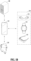
- FIG. 1B is a diagram illustrating an example of a system including a wearable device according to an embodiment.
- an electronic device 110 may communicate with the wearable device 120 and remotely control the wearable device 120.
- the electronic device 110 may be an electronic device in various forms.
- the electronic device 110 may include, for example, a portable communication device (e.g., a smartphone), a computer device, a portable multimedia device, or a home appliance device but is not limited thereto.
- the electronic device 110 may be differently expressed as a user terminal.
- the electronic device 110 may communicate with the wearable device 120 to identify a state (e.g., a booting state, a state of charge, a scanning state, a sensing state, an utterance state, or an error state, which are to be described below) of the wearable device 120.
- the electronic device 110 may transmit, to the wearable device 120, a control signal instructing that feedback corresponding to the identified state be provided to a user.
- the wearable device 120 may provide (or output) the feedback (e.g., at least one of visual feedback, auditory feedback, and tactile feedback) corresponding to the state of the wearable device 120 according to a control signal.
- the electronic device 110 may provide (or output) feedback (e.g., at least one of visual feedback, auditory feedback, and tactile feedback) corresponding to the state of the wearable device 120.
- the wearable device 120 and/or the electronic device 110 may connect to other wearable devices 130.
- the wearable device 120, the electronic device 110, and the other wearable devices 130 may be connected, directly or indirectly, to one another through wireless communication (e.g., Bluetooth' communication).
- the other wearable devices 130 may include, for example, wireless earphones 131, a smart watch 132, or smart glasses 133 but are not limited thereto.
- the smart watch 132 may be a watch-type wearable device (or watch-type electronic device) and the smart glasses 133 may be a glasses-type wearable device (or glasses-type electronic device).
- the smart watch 132 may obtain the user's biometric information (e.g., heart rate information) and transmit the obtained biometric information to the electronic device 110.
- biometric information e.g., heart rate information
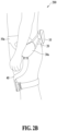
- the smart watch 132 may control the wearable device 120.
- the smart watch 132 may control the wearable device 120 through the electronic device 110 when the smart watch 132 is connected, directly or indirectly, to the electronic device 110 through a wireless communication link and the electronic device 110 is connected to the wearable device 120 through a wireless communication link.
- the smart watch 132 may directly connect to the wearable device 120 and may control the wearable device 120.
- the electronic device 110 may transmit, to the other wearable devices 130, a control signal instructing that feedback corresponding to a state of the wearable device 120 be provided to the user 101.
- the other wearable devices 130 may provide (or output) feedback (e.g., at least one of visual feedback, auditory feedback, and tactile feedback) corresponding to the state of the wearable device 120 according to the received control signal.
- the electronic device 110 may be connected, directly or indirectly, to a server 140 by using short-range wireless communication (e.g., Wi-Fi) or mobile communication (e.g., 4th generation (4G) mobile communication systems, 5G, and the like).
- short-range wireless communication e.g., Wi-Fi
- mobile communication e.g., 4th generation (4G) mobile communication systems, 5G, and the like.
- the electronic device 110 may receive profile information of the user 101 from the user 101.
- the profile information may include, for example, at least one of a name, age, gender, height, weight, and body mass index (BMI).
- BMI body mass index
- the electronic device 110 may transmit the profile information of the user 101 to the server 140.
- the electronic device 110 and/or the wearable device 120 may request the user 101 to perform one or more target motions so as to determine (or check) the motion ability of the user 101.
- the one or more target motions may include, for example, lifting a knee, extending a leg backward, and the like.
- Lifting the knee may be a pose starting from the user 101 uprightly standing with their feet on the ground and returning to the standing pose after the user 101 maximally extends their leg backward without bending their waist.
- Extending the leg backward may be a pose starting from the user 101 uprightly standing with their hands against a wall and returning to the standing pose after maximally extending their leg backward without bending their waist.
- the wearable device 120 may obtain motion information of the user 101 who performs a target motion by using a sensor (e.g., an Inertial Measurement Unit (IMU)) and transmit the obtained motion information to the electronic device 110.
- a sensor e.g., an Inertial Measurement Unit (IMU)
- the electronic device 110 may transmit the obtained motion information to the server 140.
- IMU Inertial Measurement Unit
- the server 140 may determine a target amount of exercise for each exercise type (e.g., a muscle exercise, a balance exercise, and a cardio exercise) of the user 101 through the profile information and the motion information received from the electronic device 110.
- the server 140 may transmit the target amount of exercise for each exercise type to the electronic device 110.
- the electronic device 110 may execute a fitness application and display an execution screen including the target amount of exercise for each exercise type on a display.
- the server 140 may include a database storing information about a plurality of exercise programs that may be provided to the user 101 through the wearable device 120.
- the server 140 may manage a user account of the user 101 of the electronic device 110 or the wearable device 120.
- the server 140 may store and manage an exercise program performed by the user 101 and a result of the exercise program in association with the user account.
- the electronic device 110 and/or the server 140 may provide the user 101 with various exercise programs to achieve an exercise target in various exercise environments desired by the user 101.
- the exercise target may include, for example, at least one of muscle strength improvement, physical strength improvement, cardiorespiratory endurance improvement, core stability improvement, flexibility improvement, and symmetry improvement, or a combination thereof.
- the electronic device 110 and/or the server 140 may recommend an exercise program to the user 101 in order to achieve the exercise target of the user 101.
- Each exercise program may include one or more exercise modes.
- each exercise mode may be for a body motion to achieve a specific exercise target.
- running may be an exercise mode for improving the cardiorespiratory endurance of the user 101.
- a lunge may be an exercise mode for improving the core stability of the user 101.
- Combinations of a plurality of exercise modes in each exercise program may variously appear according to an exercise target of the user 101.
- the electronic device 110 may provide the user 101 with various exercise programs according to a combination of the plurality of exercise modes even for the same exercise target.
- the plurality of exercise programs may be converted into a database and stored in the electronic device 110 or in the server 140.
- the electronic device 110 or the server 140 may generate the plurality of exercise programs based on various sets of information about the user 101 and recommend, to the user 101, a target exercise program among the plurality of exercise programs, considering an exercise target of the user 101 or an exercise performance state of the user 101.
- the electronic device 110 or the server 140 may determine a target exercise program to recommend to the user 101 based on at least one of an exercise target, exercise history, and an exercise performance result of the user 101. Accordingly, the user 101 may be recommended a new exercise program even when the user 101 exercises for the same exercise target and the user 101 may perform the new exercise program, feeling as if the user 101 is performing a different exercise from an existing one.
- FIG. 2A is a rear schematic diagram illustrating a wearable device according to an embodiment.
- FIG. 2B is a left side view illustrating the wearable device according to an embodiment.
- a wearable device 200 (e.g., the wearable device 120) according to an embodiment may include a base body 10, a base frame 20, driving modules 30a and 30b, and a pair of arms 40, and a main belt 50.
- the base body 10 may be on the lumbar (or the waist) of a user when the user wears the wearable device 200.
- the base body 10 worn on the user's lumbar may cushion the user's waist to support the user's waist.
- the base body 10 may be above the user's hip when the user wears the wearable device 200 such that the wearable device 200 may not be deviated downward by gravity.
- the base body 10 may disperse some of the weight of the wearable device 200 to the waist of the user wearing the wearable device 200.
- the base body 10 may connect to the base frame 20.
- Base frame connection elements (not shown) which may connect to the base frame 20 may be at both ends of the base body 10.
- the base body 10 may include a lighting unit 60.
- the lighting unit 60 may include a plurality of light sources (e.g., light-emitting diodes (LEDs)).
- the lighting unit 60 may emit light according to control of a processor (not shown) (e.g., a processor 310 of FIGS. 3A and 3B ).
- the processor may control the lighting unit 60 to provide (or output) visual feedback corresponding to a state of the wearable device 200 to the user through the lighting unit 60.
- the base frame 20 may extend from both ends of the base body 10.
- the user's lumbar may be accommodated inside the base frame 20.
- the base frame 20 may include at least one rigid body beams. Each rigid body beam may have a curved shape having a preset curvature to surround the user's lumbar.
- the main belt 50 may connect to an end of the base frame 20.
- the driving module 30 may be mounted on the base frame 20.
- the base frame 20 may include a connector (not shown) for equipping the driving module 30.
- the driving module 30 may include the first driving module 30a that is on the user's left side when the user wears the wearable device 200 and the second driving module 30b that is on the user's right side when the user wears the wearable device 200.
- Each driving module herein may comprise a motor and/or circuitry, for example as shown in Figs. 3A-3B .
- the first driving module 30a may include a first actuator (not shown) and a first joint member (not shown) and the second driving module 30b may include a second actuator (not shown) and a second joint member (not shown).
- the first actuator may provide power to be transmitted to the first joint member and the second actuator may provide power to be transmitted to the second joint member.
- Each of the first actuator and the second actuator may include a motor generating power after receiving power from a battery (e.g., a battery 330 of FIGS. 3A and 3B ). When driven by received power, the motor may provide an assistive force for assisting the user's body motion or a resistance force to impede the user's body motion.
- the first joint member may be rotated by the power received from the first actuator.
- a first encoder for measuring a rotation angle of the first joint member may be on one side of the first joint member.
- the second joint member may be rotated by the power received from the second actuator.
- a second encoder for measuring a rotation angle of the second joint member may be on one side of the second joint member.
- the driving module 30 may be mounted on and fixed to the base frame 20.
- the driving module 30 may transmit power to the pair of arms 40.
- the driving module 30 may be on the side of the user's thigh, the side of the user's lumbar, or therebetween while the user is wearing the wearable device 200.
- the pair of arms 40 may be worn on both the user's legs.
- the pair of arms 40 may receive power from the driving module 30 and press the user's legs in a direction of assisting the motion of the user's thighs, knees, and calves.
- the pair of arms 40 may include a support unit for surrounding the user's legs and a connection frame for connecting the support unit to the driving module 30.
- the main belt 50 may connect to the base frame 20.
- the main belt 50 may include a first main belt 50a that may wrap around the user's left abdomen when the user wears the wearable device 200 and a second main belt 50b that may wrap around the user's right abdomen when the user wears the wearable device 200.
- the first main belt 50a may be formed in a shape having a longer length than the second main belt 50b but is not limited thereto.
- the first main belt 50a may have the same length as the second main belt 50b or a shorter length than the second main belt 50b.
- the first main belt 50a and the second main belt 50b may, respectively, connect to both ends of the base frame 20.
- the main belt 50 When the main belt 50 is inserted in a direction in which the user's body is accommodated in the wearable device 200, the main belt 50 may be bent in a direction surrounding the user's abdomen.
- the first main belt 50a may connect to the second main belt 50b when the user wears the wearable device 200.
- the main belt 50 may disperse some of the weight of the wearable device 200 to the user's abdomen when the user wears the wearable device 200.
- the base body 10 may be mounted on the back of the user's lumbar and may support some of the weight of the wearable device 200 by hanging on the user's buttocks.
- the first driving module 30a may be on the user's left lumbar.
- the base frame 20 may be inclined in a direction extending from an end of the base body 10 toward the first driving module 30a.
- the first main belt 50a mounted on the base frame 20 may be wrapped around the user's left abdomen.
- the arms 40 may be mounted on the user's legs and receive power from the first driving module 30a.
- FIGS. 3A and 3B illustrate examples of a configuration of a wearable device according to an embodiment.
- a wearable device 300 may include a processor 310, angle sensors 320 and 320-1, a battery 330, and a Power Management Integrated Circuit (PMIC) 340, a memory 350, an IMU 360, motor driver circuits 370 and 370-1, motors 380 and 380-1, and a communication module 390 comprising communication circuitry.
- PMIC Power Management Integrated Circuit
- a wearable device 300-1 shown in FIG. 3B may include one sensor 320, one motor driver circuit 370, and one motor 380.
- the wearable devices 300 and 300-1 may include a plurality of processors. The number of motor driver circuits, the number of motors, or the number of processors may vary depending on a body part on which the wearable devices 300 and 300-1 are worn.
- the angle sensor 320, the motor driver circuit 370, and the motor 380 may be included in the first driving module 30a of FIG. 2A .
- the angle sensor 320-1 and the motor driver circuit 370-1, and the motor 380-1 may be included in the second driving module 30b of FIG. 2A .
- the angle sensor 320 may measure or sense an angle of a first joint (e.g., the left hip joint) of the user.
- the angle sensor 320 may transmit, to the processor 310, first angle information obtained by measuring the angle of the first j oint.
- the angle sensor 320 may measure the angle of the user's left hip joint and transmit angle information obtained by measuring the angle of the left hip joint to the processor 310.
- the PMIC 340 may transfer power stored in the battery 330 to components in the wearable devices 300 and 300-1.
- the PMIC 340 may, for example, adjust power stored in the battery 330 to a voltage level or a current level suitable for components (e.g., the processor 310, the angle sensors 320 and 320-1, the memory 350, the IMU 360, the motors 380 and 380-1, and the like) in the wearable device 300.
- the PMIC 340 may include, for example, a converter (e.g., a direct current (DC)-DC converter) or a regulator (e.g., a low dropout (LDO) regulator or a switching regulator) capable of performing the adjustment described above.
- a converter e.g., a direct current (DC)-DC converter
- a regulator e.g., a low dropout (LDO) regulator or a switching regulator
- the motor driver circuits 370 and 370-1 may control the motors 380 and 380-1, respectively, based on the control information received from the processor 310. By the controlling, the motors 380 and 380-1 may each generate torque.
- the communication module 390 may support the establishment of a direct (e.g., wired) communication channel or a wireless communication channel between the wearable electronic devices 300 and 300-1 and an external electronic device and may support the communication performance through the established communication channel.
- the communication module 390 may include one or more communication processors configured to support direct (e.g., wired) communication or wireless communication.
- the communication module 390 may include a wireless communication module (e.g., a cellular communication module, a short-range wireless communication module, or a global navigation satellite system (GNSS) communication module) or a wired communication module (e.g., a local area network (LAN) communication module or a power line communication module).
- GNSS global navigation satellite system
- a corresponding one of these communication modules may communicate with the external electronic device via a first network (e.g., a short-range communication network, such as Bluetooth TM , Wi-Fi direct, or IrDA) or a second network (e.g., a legacy cellular network, a 5G network, a next-generation communication network, the Internet, or a computer network).
- a first network e.g., a short-range communication network, such as Bluetooth TM , Wi-Fi direct, or IrDA
- a second network e.g., a legacy cellular network, a 5G network, a next-generation communication network, the Internet, or a computer network.
- These various types of communication modules may be implemented as a single component (e.g., a single chip) or may be implemented as components (e.g., chips) separate from each other.
- the wearable devices 300 and 300-1 may each include a display module.
- the display module may include, for example, a display and/or a lighting unit (e.g., the lighting unit 60 of FIG. 2A ).
- the processor 310 may control the display module to provide visual feedback to the user.
- the wearable devices 300 and 300-1 may include a sound output module.
- the sound output module may include, for example, a speaker.
- the processor 310 may control the sound output module to provide auditory feedback to the user.
- the wearable devices 300 and 300-1 may include a vibration output module.
- the vibration output module may include, for example, a vibration motor.
- the processor 310 may control the vibration output module to provide tactile feedback (or haptic feedback) to the user.
- the base body 10 of FIGS. 2A and 2B may include at least one of the processor 310, the battery 330, the PMIC 340, the memory 350, the IMU 360, the communication module 390, the display module, the sound output module, and the vibration output module, or a combination thereof.
- FIG. 4 is a block diagram illustrating an example of a configuration of an electronic device according to an embodiment.
- an electronic device 400 may include a processor 410, a communication module 420, a memory 430, and a display 440.
- the communication module 420 may establish a wireless communication link with a wearable device (e.g., the wearable device 300 or the like).
- the wireless communication link may include, for example, a Bluetooth link or a Bluetooth Low Energy (BLE) link but is not limited thereto.
- BLE Bluetooth Low Energy
- the memory 430 may store a fitness application.
- the fitness application may recommend an exercise program to a user, provide a target amount of exercise to the user, and manage a result of the user's exercise performance when the user performs an exercise with the wearable device 300 worn on the user's body.
- the processor 410 may execute the fitness application and control the display 440 to display a screen of the executed fitness application on the display 440.
- the screen of the executed fitness application may include a first area.
- the processor 410 may control the display 440 to provide visual feedback corresponding to a state of the wearable device 300 to the user through the first area.
- the processor 410 may receive state information indicating that the wearable device 300 is in a booting state from the wearable device 300 through the communication module 420.
- the processor 410 may recognize (or determine) a state of the wearable device 300 as the booting state according to the state information indicating the booting state.
- the processor 410 may control the display 440 to provide visual feedback corresponding to the booting state of the wearable device 300 through the first area of the execution screen of the fitness application. For example, for the visual feedback corresponding to the booting state of the wearable device 300, the processor 410 may control the display 440 to display a first color on a user interface (UI) (e.g., a first object 612 of FIG. 6A to be described below or a second object 622 of FIG.
- UI user interface
- the processor 410 may also control the display 440 to change the first color of the UI to a second color.
- the first color may be, for example, one of shades of white or white but is not limited thereto.
- the second color may be, for example, one of shades of blue or blue but is not limited thereto.
- the processor 410 may receive state information indicating that the wearable device 300 is in a state of charge from the wearable device 300 through the communication module 420.
- the processor 410 may recognize (or determine) a state of the wearable device 300 as the state of the charge according to the state information indicating the state of the charge.
- the processor 410 may control the display 440 to provide visual feedback corresponding to the state of charge of the wearable device 300 through the first area of the execution screen of the fitness application. For example, for the visual feedback corresponding to the state of charge of the wearable device 300, the processor 410 may determine an area where the first color is represented on the UI (e.g., the first object 612 of FIG. 6A to be described below or the second object 622 of FIG.
- the processor 410 may also control the display 440 to move the area where the first color is represented on the UI according to an increase in the charging rate of the wearable device 300.
- the processor 410 may transmit, to the wearable device 300 through the communication module 420, a control signal instructing the wearable device 300 to perform scanning.
- the scanning may indicate an operation in which the wearable device 300 determines whether the user is ready to start an exercise.
- the processor 410 may receive, through the communication module 420, state information indicating that the wearable device 300 is in a scanning state for performing scanning.
- the processor 410 may recognize (or determine) a state of the wearable device 300 as the scanning state according to state information indicating that the wearable device 300 is in the scanning state.
- the processor 410 may control the display 440 to provide visual feedback corresponding to the scanning state through the first area of the execution screen of the fitness application.
- the processor 410 may control the display 440 to move an area where the second color is represented on the UI (e.g., the first object 612 of FIG. 6A to be described below or the second object 622 of FIG. 6B to be described below) of the first area.
- the UI e.g., the first object 612 of FIG. 6A to be described below or the second object 622 of FIG. 6B to be described below
- the processor 410 may receive state information indicating that the wearable device 300 is in a sensing state for sensing the user's motion (e.g., an exercise motion).
- the processor 410 may recognize (or determine) a state of the wearable device 300 as the sensing state according to the state information indicating that the wearable device 300 is in the sensing state.
- the processor 410 may control the display 440 to provide visual feedback corresponding to the sensing state of the wearable device 300 through the first area of the execution screen of the fitness application. For example, for the visual feedback corresponding to the sensing state, the processor 410 may control the display 440 to sequentially represent each of colors on the UI (e.g., the first object 612 of FIG. 6A to be described below or the second object 622 of FIG. 6B to be described below) of the first area.
- the UI e.g., the first object 612 of FIG. 6A to be described below or the second object 622 of FIG. 6B to be described below
- the processor 410 may receive, from the wearable device 300, an evaluation result of an exercise pose and state information indicating that the wearable device 300 is in an utterance state in which the wearable device 300 outputs the evaluation result of the user's exercise pose in an utterance voice.
- the processor 410 may recognize (or determine) a state of the wearable device 300 as the utterance state according to the state information indicating that the wearable device 300 is in the utterance state.
- the processor 410 may control the display 440 to provide visual feedback corresponding to the utterance state of the wearable device 300 through the first area of the execution screen of the fitness application.
- the processor 410 may control the display 440 to repeatedly extend and reduce the area where the second color is represented on the UI (e.g., the first object 612 of FIG. 6A to be described below or the second object 622 of FIG. 6B to be described below) of the first area.
- a visual effect as if the electronic device 400 is speaking may be provided to the user.
- the processor 410 may control the wearable device 300 not to output an utterance voice.
- the processor 410 may generate an utterance voice based on the received evaluation information and transmit the generated utterance voice to the wireless earphones so that the generated utterance voice may be output through the wireless earphones.
- the user may listen to the utterance voice of the evaluation result of the exercise pose through the wireless earphones.
- the processor 410 may receive a request of the wearable device 300 for wireless communication connection through the communication module 420.
- the processor 410 may control the display 440 to provide visual feedback indicating that the electronic device 400 is connecting to the wearable device 300, through the first area of the execution screen of the fitness application.
- the processor 410 may control the display 440 to periodically change the predetermined size of the area where the second color is represented on the UI (e.g., the first object 612 of FIG. 6A to be described below or the second object 622 of FIG. 6B to be described below) of the first area.
- a visual effect such as flickering of the second color light, may be provided to the user.
- the user may easily recognize that the electronic device 400 is connecting to the wearable device 300.
- the processor 410 may not provide the visual feedback indicating that the connection is in progress.
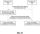
- the processor 410 may receive, from the wearable device 300, state information indicating an error situation occurs in the wearable device 300.
- the error situation may include, for example, an error where an error occurs in the wearable device 300, an error where the user wears the wearable device 300 incorrectly, an error where the user falls, and the like.
- the processor 410 may recognize (or determine) a state of the wearable device 300 as the error state according to the state information indicating that an error situation occurs.
- the processor 410 may control the display 440 to provide visual feedback corresponding to the error state of the wearable device 300 through the first area of the execution screen of the fitness application.
- the processor 410 may control the display 440 to periodically change the density of the first color on the UI (e.g., the first object 612 of FIG. 6A to be described below or the second object 622 of FIG. 6B to be described below) of the first area.
- a visual effect such as flickering of the first color light, may be provided to the user. The user may easily recognize that an error occurs in the wearable device 300.
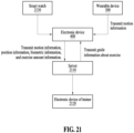
- the processor 410 may receive motion information obtained by sensing the user's motion, from the wearable device 300 through the communication module 420.
- the processor 410 may transmit the motion information, the user's position information, the user's biometric information (e.g., heart rate information, and the like), and information about the amount of the user's exercise to a server (e.g., the server 140 of FIG. 1B ) through the communication module 420.
- the server may determine guide information about the user's exercise based on the motion information, position information, biometric information and information about the amount of exercise, which are all received, and environment information (e.g., the weather, topography, and the like) of the area where the user is.
- the server may transmit the determined guide information to the electronic device 400.
- the processor 410 may control the display 440 to provide the received guide information through the first area of the execution screen of the fitness application.
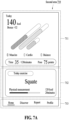
- FIGS. 5 to 7B are diagrams illustrating examples of execution screens of a fitness application of an electronic device according to an embodiment.
- an execution screen 500 of a fitness application may include a first area 510 and a second area 520.
- Visual feedback corresponding to a state of the wearable device 300 may be displayed on the first area 510 and text may be displayed thereon.
- the first area 510 may be a fixed area and in some execution screens (e.g., a setting screen) of the fitness application, the first area 510 may not be provided.
- an analysis result e.g., an evaluation result of an exercise pose
- AI Artificial Intelligence
- a target amount of exercise and/or a recommended exercise for each of exercise types may be displayed.
- a guide image for an exercise being performed by the user may be displayed on the second area 520.
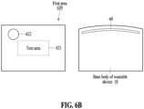
- Examples of the first area 510 are shown in FIGS. 6A and 6B .
- a first area 610 may include a text area 611 and a first object 612.
- the processor 410 may display text on the text area 611.
- the processor 410 may provide visual feedback corresponding to a state of the wearable device 300 to the user through the first object 612.
- the lighting unit 60 of the base body 10 of the wearable device 300 may provide visual feedback corresponding to a state of the wearable device 300 to the user.
- the visual feedback provided through the first object 612 may be synchronized with the visual feedback provided through the lighting unit 60.
- the shape of the first object 612 may correspond to the shape of the lighting unit 60.
- a first area 620 may include a text area 621 and a second object 622.
- the second object 622 may have a circular shape and may be at the top left of the text area 621.
- the shape and position of the second object 622 are not limited to those shown in FIG. 6B .
- the processor 410 may display text on the text area 621.
- the processor 410 may provide visual feedback corresponding to a state of the wearable device 300 to the user through the second object 622.
- the lighting unit 60 of the base body 10 of the wearable device 300 may provide visual feedback corresponding to a state of the wearable device 300 to the user.
- the visual feedback provided through the second object 622 may be synchronized with the visual feedback provided through the lighting unit 60.
- a recommended exercise may be displayed on the second subarea 712.
- a video of the recommended exercise may be played or a description of the recommended exercise may be provided.
- a plurality of menu buttons may be displayed on the third subarea 713.
- An execution screen including the first area 510 e.g., the first area 610 of FIG. 6A or the first area 620 of FIG. 6B
- the second area 710 of FIG. 7A may be a home screen.
- the processor 410 may control the display 440 to display the home screen on the display 440.
- the processor 410 may control the display 440 to display, on the display 440, a screen including an exercise list in an exercise program to be performed by the user.
- the processor 410 may control the display 440 to display, on the display 440, a screen including a report on an execution result of the exercise program.
- the processor 410 may control the display 440 to display, on the display 440, a screen including user information (e.g., an ID and the like).
- a second area 720 may include subareas 721, 722, and 723.
- curved objects may form a circle.
- a recommended exercise may be displayed on the second subarea 722, and a plurality of menu buttons (e.g., a home menu button, a discovery menu button, a report menu button, and a profile menu button) may be displayed on the third subarea 723.
- a description of the second subarea 722 and the third subarea 723 may be applied to the description of the second subarea 712 and the third subarea 713.
- the execution screen 500 of FIG. 5 may include, for example, the first area 610 of FIG. 6A and the second area 710 of FIG. 7A ; the first area 610 of FIG. 6A and the second area 720 of FIG. 7B ; the first area 620 of FIG. 6B and the second area 710 of FIG. 7A ; or the first area 620 of FIG. 6B and the second area 720 of FIG. 7B .
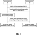
- the wearable device 300 may transmit, to the electronic device 400, state information indicating that the wearable device 300 is in a booting state.
- the electronic device 400 may recognize (or determine) a state of the wearable device 300 as the booting state, upon receipt of the state information indicating that the wearable device 300 is in the booting state from the wearable device 300.
- the electronic device 400 may transmit, to the wearable device 300, a control signal instructing that feedback corresponding to the booting state be provided.
- the electronic device 400 may provide visual feedback corresponding to the booting state to the user.
- the processor 410 of the electronic device 400 may control the display 440 to display a first color on an object (e.g., the first object 612 of FIG. 6A or the second object 622 of FIG. 6B ) of a first area of the screen of the fitness application and may control the display 440 to change the first color on the object (e.g., the first object 612 of FIG. 6A or the second object 622 of FIG. 6B ) to a second color.
- the wearable device 300 may provide the visual feedback corresponding to the booting state to the user.
- the processor 310 of the wearable device 300 may control the lighting unit 60 to output light of the first color and control the lighting unit 60 to change the first color output by the lighting unit 60 to the second color.
- the wearable device 300 may provide haptic feedback and/or auditory feedback indicating the booting state to the user along with the visual feedback.
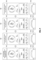
- Examples of operations 850 and 860 are described with reference to FIG. 9 .
- Each of screens 910 to 940 of FIG. 9 may be an example of the execution screen 500 of FIG. 5 .
- the wearable device 300 may be in a non-booting state and the processor 410 of the electronic device 400 may control the display 440 to display the screen 910 of the fitness application on the display 440.
- a first object 901 (e.g., the first object 612 of FIG. 6A ) represented in a second color and text may be displayed on the first area 510 of the screen 910.
- the second color of the first object 901 may be an example, and the first color or a color having lower concentration than the first color may be represented in the first object 901.
- objects of a second shape e.g., a curved shape
- a target amount of exercise for each of exercise types, an exercise time of the user, an exercise pose score of the user, and calories consumed by the user during exercise, a recommended exercise, and a plurality of menu buttons may be displayed.
- a lighting unit 903 (e.g., the lighting unit 60 of FIG. 2A ) of the wearable device 300 may not output light.
- the processor 410 of the electronic device 400 transmits, to the wearable device 300, a control signal instructing that feedback corresponding to a booting state be provided (or recognizes a state of the wearable device 300 as the booting state), the processor 410 may control the display 440 to represent the first object 901 in the first color.
- the first object 901 represented in the first color and text may be displayed on the first area 510 of the screen 920.
- the electronic device 400 may provide the user with a visual effect, such as outputting light of the first color.
- the processor 310 of the wearable device 300 may control the lighting unit 903 to output light of the first color.
- the first object 901 represented in the first color may be synchronized with the lighting unit 903 outputting the light of the first color.
- the processor 410 of the electronic device 400 may control the display 440, so that the first object 901 represented in the first color may be gradually represented in the second color.
- the processor 310 of the wearable device 300 may control the lighting unit 903, so that the lighting unit 903 outputting light of the first color may gradually output light of the second color.
- the processor 410 of the electronic device 400 may change a color of the central portion of the first object 901 represented in the first color from the first color to the second color.
- the processor 410 of the electronic device 400 may change the first color to the second color from the central portion of the first object 901 to the edge of the first object 901.
- the second color may be represented on an area other than the edge of the first object 901 of the screen 930 shown in FIG. 9 and the first color may be represented around the edge of the first object 901.
- the processor 310 of the wearable device 300 may control the lighting unit 903, so that the central portion of the lighting unit 903 outputting light of the first color may output light of the second color.
- the processor 310 of the wearable device 300 may control the lighting unit 903, so that the light of the second color may be output from the central portion of the lighting unit 903 to the edge of the lighting unit 903.
- the light of the second color may be output in an area other than the edge of the lighting unit 903 and the light of the first color may be output around the edge of the lighting unit 903.
- the first object 901 may be represented in the second color.
- the lighting unit 903 may output light of the second color.
- the first object 901 represented in the second color and the lighting unit 903 outputting the light of the second color may correspond to complete booting of the wearable device 300.
- the first object 901 represented in the second color and text may be displayed on the first area 510 of the screen 940 shown in FIG. 9 .
- the processor 310 of the wearable device 300 may control the lighting unit 903 to output the light of the second color.
- the electronic device 400 may provide the user with visual feedback (e.g., a visual effect of gradually changing the first color of the first object 901 to the second color) corresponding to the booting state.
- the wearable device 300 may provide the user with the visual feedback (e.g., a visual effect of gradually changing the color of light output by the lighting unit 903 from the first color to the second color). Accordingly, the user may easily recognize that the wearable device 300 is in the booting state.
- the electronic device 400 may connect to the smart watch 132 through a wireless communication link.
- the smart watch 132 may communicate with the electronic device 400 and display, on its display, the visual feedback corresponding to the booting state of the wearable device 300.
- the smart watch 132 may be synchronized with the electronic device 400. Through such synchronization, the smart watch 132 may display the same screen as the first area 510 of each of the screens 910 to 940 of FIG. 9 on its display.
- FIGS. 10 and 11 are diagrams illustrating examples of providing visual feedback corresponding to a state of charge of a wearable device according to an embodiment.
- the wearable device 300 may transmit state information indicating that the wearable device 300 is in a state of charge to the electronic device 400. For example, when the wearable device 300 is connected, directly or indirectly, to a charging cable (or wirelessly charged), the wearable device 300 may transmit state information indicating that the wearable device 300 is in the state of charge to the electronic device 400.
- the electronic device 400 may determine (or recognize) a state of the wearable device 300 to be the state of charge when the electronic device 400 receives, from the wearable device 300, the state information indicating that the wearable device 300 is in the state of charge.
- the electronic device 400 may transmit, to the wearable device 1030, a control signal instructing feedback corresponding to the state of charge be provided.
- the electronic device 400 may provide visual feedback corresponding to the state of charge to the user.
- the processor 410 of the electronic device 400 may determine an area to be represented in the first color in an object (e.g., the first object 612 of FIG. 6A or the second object 622 of FIG. 6B ) of the first area of the screen of the fitness application.
- the processor 410 of the electronic device 400 may control the display 440 to display the first color on the determined area.
- the processor 410 of the electronic device 400 may control the display 440 to provide a visual effect of moving the area, in which the first color is represented in the object (e.g., the first object 612 of FIG. 6A or the second object 622 of FIG. 6B ) as the charging rate of the wearable device 300 increases.
- the wearable device 300 may provide the user with the visual feedback corresponding to the state of charge.
- the processor 310 of the wearable device 300 may determine an area (or some light sources) where the lighting unit 60 is to output the first color.
- the processor 310 of the wearable device 300 may control the lighting unit 60 to output light of the first color on the determined area.
- the processor 310 of the wearable device 300 may control the display 440 to provide a visual effect of moving the area where the lighting unit 60 outputs the light of the first color as the charging rate of the wearable device 300 increases.
- the wearable device 300 may provide the user with haptic feedback and/or auditory feedback corresponding to the state of charge along with the visual feedback.
- FIGS. 12 and 13 are diagrams illustrating examples of providing visual feedback corresponding to a scanning state of a wearable device according to an embodiment.
- the wearable device 300 may transmit, to the electronic device 400, a determined exercise state (e.g., an exercise speed, an exercise intensity, and the like).
- the wearable device 300 may transmit a determined exercise speed (e.g., a low speed, a medium speed, or a high speed) to the electronic device 400.
- the wearable device 300 may transmit a determined exercise intensity (e.g., an extremely low exercise intensity, a low exercise intensity, a medium exercise intensity, a high exercise intensity, or an extremely high exercise intensity) to the electronic device 400.
- Operation 2210 is described as being performed by the wearable device 300 above but this is only an example. Operation 2210 may be performed by the electronic device 400.
- the wearable device 300 may transmit a measurement result of a sensor (e.g., the IMU 360) to the electronic device 400.
- the electronic device 400 may determine a exercise speed (e.g., a low speed, a medium speed, or a fast speed) of the user by using the received measurement result.
- the electronic device 400 may determine a exercise intensity (e.g., an extremely low exercise intensity, a low exercise intensity, a medium exercise intensity, a high exercise intensity, or an extremely high exercise intensity) of the user through the user's heart rate information.
- the electronic device 400 may provide visual feedback corresponding to the determined exercise state.
- the wearable device 300 may provide the user with visual feedback corresponding to a determined exercise state (e.g., an exercise speed) through the lighting unit 903.
- the electronic device 400 may provide the visual feedback corresponding to the determined exercise state (e.g., an exercise speed) to the user.
- the processor 310 of the wearable device 300 may control the lighting unit 903 to perform the second breathing effect described above at a first speed when the user's exercise speed corresponds to a low speed.
- the processor 410 of the electronic device 400 may control the display 440 to provide the first breathing effect described above at the first speed through the first object 901 of the screen 2310.
- a screen 2410 of FIG. 24 may be an example of the execution screen 500 of FIG. 5 .
- the wearable device 300 may provide the user with visual feedback corresponding to a determined exercise state (e.g., an exercise intensity) through the lighting unit 903.
- the electronic device 400 may provide visual feedback corresponding to the determined exercise state (e.g., an exercise intensity) to the user through the screen 2410.
- the processor 310 of the wearable device 300 may control the lighting unit 903, so that light sources in an area (a first area) corresponding to the extremely low exercise intensity in the lighting unit 903 may output the light of the first color.
- the processor 410 of the electronic device 400 may control the display 440 to display the first color on an area (a first area) corresponding to the extremely low exercise intensity in the first object 901 of the screen 2410.
- the processor 310 of the wearable device 300 may control the lighting unit 903, so that light sources of areas (the first area and a second area) corresponding to the low exercise intensity in the lighting unit 903 may output the light of the first color.
- the processor 410 of the electronic device 400 may control the display 440 to display the first color on areas (the first area and a second area) corresponding to the low exercise intensity in the first object 901 of the screen 2410.
- the processor 310 of the wearable device 300 may control the lighting unit 903, so that light sources of areas (the first area, the second area, and a third area) corresponding to the medium exercise intensity in the lighting unit 903 may output the light of the first color.
- the processor 410 of the electronic device 400 may control the display 440 to display the first color on areas (the first area, the second area, and a third area) corresponding to the medium exercise intensity in the first object 901 of the screen 2410.
- the processor 310 of the wearable device 300 may control the lighting unit 903, so that light sources of areas (the first area, the second area, the third area, and a fourth area) corresponding to the high exercise intensity in the lighting unit 903 may output the light of the first color.
- the processor 410 of the electronic device 400 may control the display 440 to display the first color on areas (the first area, the second area, the third area, and a fourth area) corresponding to the high exercise intensity in the first object 901 of the screen 2410.
- the processor 310 of the wearable device 300 may control the lighting unit 903, so that light sources of areas (the first area, the second area, the third area, the fourth area, and a fifth area) corresponding to the extremely high exercise intensity in the lighting unit 903 may output the light of the first color.
- the processor 410 of the electronic device 400 may control the display 440 to display the first color on areas (the first area, the second area, the third area, the fourth area, and a fifth area) corresponding to the extremely high exercise intensity in the first object 901 of the screen 2410.
- FIGS. 25 and 26 An example of providing visual feedback corresponding to an exercise state (e.g., heart rate information) of the user is described with reference to FIGS. 25 and 26 .
- the electronic device 400 may determine a heart rate state of the user.
- the electronic device 400 may receive heart rate information of the user from the smart watch 132 and determine a heart rate state of the user based on the received heart rate information. For example, when the received heart rate information is 70 to 80% of the maximum heart rate of the user, the electronic device 400 may determine a heart rate state of the user to be a medium state (or a first heart rate state). When the received heart rate information is 80 to 90% of the maximum heart rate of the user, the electronic device 400 may determine a heart rate state of the user to be a hard state (or a second heart rate state).
- the electronic device 400 may determine a heart rate state of the user to be a maximum state (or a third heart rate state).
- a maximum state or a third heart rate state.
- An example of determining the heart rate state is not limited to the examples described above.
- the heart rate state is categorized into three stages above, they are only examples.
- the electronic device 400 may transmit a heart rate state (e.g., a medium state, a hard state, or a maximum or high state) of the user to the wearable device 300.
- a heart rate state e.g., a medium state, a hard state, or a maximum or high state
- the electronic device 400 may provide visual feedback corresponding to the heart rate state to the user.
- the wearable device 300 may provide the visual feedback corresponding to the heart rate state to the user.
- Examples of operations 2530 and 2540 are described with reference to FIG. 26 .
- Each of screens 2610 to 2630 of FIG. 26 may be an example of the execution screen 500 of FIG. 5 .
- the wearable device 300 may provide visual feedback corresponding to a determined exercise state (e.g., a heart rate state) to the user through the lighting unit 903.
- the electronic device 400 may provide visual feedback corresponding to a determined exercise state (e.g., a heart rate state) to the user.
- the processor 310 of the wearable device 300 may control the lighting unit 903 to output light of a seventh color (e.g., green) when the heart rate state of the user corresponds to a medium state.
- the processor 410 of the electronic device 400 may control the display 440 to display the seventh color on the first object 901 of the screen 2610.
- the processor 310 of the wearable device 300 may control the lighting unit 903 to output light of an eighth color (e.g., yellow) when the heart rate state of the user corresponds to a hard state.
- the processor 410 of the electronic device 400 may control the display 440 to display the eighth color on the first object 901 of the screen 2620.
- the processor 310 of the wearable device 300 may control the lighting unit 903 to output light of a ninth color (e.g., orange) when the heart rate state of the user corresponds to a maximum or high state.
- the processor 410 of the electronic device 400 may control the display 440 to display the ninth color on the first object 901 of the screen 2630.
- FIGS. 27 and 28 are diagrams illustrating examples of providing visual feedback corresponding to a coaching-required state when a user's exercise is in a coaching-required state, according to an embodiment.
- the wearable device 300 may determine whether the user's exercise is in coaching-required state. For example, the wearable device 300 may determine that the user's exercise is in the coaching-required state when an exercise pose of the user is incorrect more than a predetermined number of times.
- the wearable device 300 may transmit, to the electronic device 400, information indicating that the user's exercise is in the coaching-required state.
- the electronic device 400 may provide the user with visual feedback corresponding to the coaching-required state.
- the wearable device 300 may provide the user with the visual feedback corresponding to the coaching-required state.
- Each of screens 2810 to 2820 of FIG. 28 may be an example of the execution screen 500 of FIG. 5 .
- the processor 410 of the electronic device 400 may control the display 440 to display the screen 2810 of the fitness application on the display 440.
- the first object 901 in which a partial area is represented in a tenth color (e.g., purple), may be displayed on the first area 510 of the screen 2810.
- the processor 310 of the wearable device 300 may control the lighting unit 903 to output light of the tenth color on the partial area of the lighting unit 903.
- the area where the light of the tenth color is output in the lighting unit 903 may correspond to the area where the tenth color is represented in the first object 901 of the screen 2810.
- the processor 410 of the electronic device 400 may control the display 440 to provide a visual effect of moving the area where the tenth color is represented in the first object 901. Accordingly, the screen 2820 of FIG. 28 may be displayed on the display 440.
- the processor 310 of the wearable device 300 may control the lighting unit 903 to provide a visual effect of moving the area where the light of the tenth color is output in the lighting unit 903.
- a trainer may easily recognize that the user is in the coaching-required state by the lighting of the lighting unit 903 of the wearable device 300.
- FIG. 29 illustrates an example of a wearable device according to an embodiment.
- a wearable device 2900 may include a processor 2910 (e.g., the processor 310), a communication module 2920 (e.g., the communication module 390 comprising communication circuitry), a sensor 2930, a driving module 2940 (e.g., the driving module 30 comprising a motor and/or circuitry), and a display module 2950.
- a processor 2910 e.g., the processor 310
- a communication module 2920 e.g., the communication module 390 comprising communication circuitry
- a sensor 2930 e.g., the driving module 2940 (e.g., the driving module 30 comprising a motor and/or circuitry)
- a driving module 2940 e.g., the driving module 30 comprising a motor and/or circuitry
- the communication module 2920 may establish a wireless communication link with the electronic device 400.
- the sensor 2930 may include the IMU 360 and/or the angle sensors 320 and/or 320-1.
- the sensor 2930 may acquire motion information by sensing the user's motion.
- the processor 2910 may transmit, to the electronic device 400, second state information indicating that the wearable device 2900 is in a booting state, through the communication module 2920.
- the processor 2910 may control the display module 2950 to provide visual feedback corresponding to the booting state through the display module 2950 (e.g., the lighting unit 60 or 903).
- the processor 2910 may evaluate a motion pose of the user by using at least some of the obtained motion information (e.g., a measurement result of the IMU 360 or angle information of each of the angle sensors 320 and/or 320-1).
- the processor 2910 may transmit, to the electronic device 400, fifth state information indicating that the wearable device 2900 is in an utterance state for outputting an evaluation result of an exercise pose in an utterance voice and the evaluation result of the exercise pose, through the communication module 2920.
- the processor 2910 may output the utterance voice through the speaker of the wearable device 2900.
- the processor 2910 may control the display module 2950 to provide visual feedback corresponding to the utterance state through the display module 2950 (e.g., the lighting unit 60 or 903).
- the smart watch 132 may display a numerical value (or a level) of exercise intensity on the area 3020.
- the exercise intensity may be related to the intensity of force (e.g., a resistance force or an assistive force) provided to the user by the wearable device 300.
- the numerical value (or level) of exercise intensity is 3.
- the maximum value may be, for example, 5, and the minimum value may be, for example, 1.
- the smart watch 132 may transmit, to the wearable device 300, a control signal instructing that the exercise intensity be lowered (or the force intensity be lowered) when there is the user's input to the intensity decrease button 3030.
- the smart watch 132 may transmit the reduced exercise intensity to the wearable device 300.
- the smart watch 132 may transmit, to the wearable device 300, a control signal instructing that the exercise intensity be lowered from 3 to 2 (or the force intensity be lowered from a force intensity corresponding to 3 to 2).
- the wearable device 300 may lower the force intensity (e.g., an assistive force) provided to the user.
- the smart watch 132 may transmit a reduced exercise intensity of "2" to the wearable device 300.
- the wearable device 300 may determine a gain according to the reduced exercise intensity of "2" and determine control information r(t) based on the determined gain, a state factor, and delay.
- the wearable device 300 may generate an assistive force based on the determined control information r(t) and provide the generated assistive force to the user.
- the smart watch 132 may transmit, to the wearable device 300, a control signal instructing that the exercise intensity be increased (or the force intensity be increased) when there is the user's input to the intensity increase button 3040.
- the smart watch 132 may transmit an increased exercise intensity to the wearable device 300.
- the smart watch 132 may transmit, to the wearable device 300, a control signal instructing that the exercise intensity be increased from 3 to 4 (or the force intensity be increased from a force intensity corresponding to 3 to 4).
- the wearable device 300 may increase the force intensity provided to the user. That is, the smart watch 132 may transmit an increased exercise intensity of "4" to the wearable device 300.
- the wearable device 300 may determine a gain according to the increased exercise intensity of"4" and determine control information ⁇ ( t ) based on the determined gain, a state factor, and delay. The wearable device 300 may generate an assistive force based on the determined control information ⁇ ( t ) and provide the generated assistive force to the user.
- the smart watch 132 may transmit, to the wearable device 300, a changed operation mode of "the resist mode" and a set exercise intensity (e.g., 3) and may display a screen 3001 on its display.
- the smart watch 132 may display an object corresponding to the resist mode on an area 3010 of the screen 3001.
- the symbol of the resistance element is displayed as the object corresponding to the resist mode on the area 3010 of the screen 3001 of FIG. 30 , this is only an example.
- the object corresponding to the resist mode may not be limited thereto.
- the wearable device 300 may change the gain from a positive gain to a negative gain and determine the size of the negative gain according to the set exercise intensity (e.g., 3).
- the wearable device 300 may change the sign of the gain from positive (+) to negative (-) and determine the size of the negative gain according to the set exercise intensity (e.g., 3).
- the wearable device 300 may determine control information ⁇ ( t ) based on the determined gain, the state factor, and the delay and generate a resistance force based on the determined the control information ⁇ ( t ) to be provided to the user.
- the smart watch 132 may display a screen (e.g., a screen 3100 of FIG. 31A to be described below) on its display while the user is exercising. While the wearable device 300 is operating in a boost mode, the smart watch 132 may sense the user's input for adjusting an exercise intensity (or changing an operation mode of the wearable device 300). In this case, the smart watch 132 may display the screen 3000 of FIG. 30 on its display. When the smart watch 132 is displaying the screen 3000 of FIG. 30 and there is the user's input to a physical button (e.g., a physical back button), the smart watch 132 may display a screen 3220 of FIG. 31A on the display.
- a physical button e.g., a physical back button
- the smart watch 132 may sense the user's input for adjusting an exercise intensity (or changing an operation mode of the wearable device 300). In this case, the smart watch 132 may display the screen 3001 of FIG. 30 on its display. While the smart watch 132 is displaying the screen 3001 of FIG. 30 and the user inputs a physical button (e.g., a physical back button), the smart watch 132 may display the screen 3100 of FIG. 31A on its display.
- a physical button e.g., a physical back button
- FIGS. 31A to 33 are diagrams illustrating other examples of controlling a wearable device by a smart watch, according to an embodiment.
- the smart watch 132 may display the screen 3100 indicating an exercise situation of the user on the display of the smart watch 132. For example, when the smart watch 132 receives, from the wearable device 300, a notification that the user is in a ready state of exercise start (or when a workout section to be described later starts), the smart watch 132 may display the screen 3100 on its display.
- the screen 3100 may include an area 3101 displaying time, an area 3102 displaying an operation mode (e.g., a boost mode or a resist mode) of the wearable device 300 and an exercise intensity value, and an area 3103 displaying an exercise time, an area 3104 displaying an exercise indicator and/or biometric information (e.g., heart rate information), and a progress bar 3105 displaying an exercise progress rate of the user.
- the exercise indicator may indicate information used for indicating an exercise state of the user or evaluating the user's exercise.
- the exercise progress rate may indicate a ratio between the user's exercise time and a target time.
- At least one of the area 3101, the area 3102, the area 3103, the area 3104, and the progress bar 3105 in the screen 3100 may be omitted.
- the smart watch 132 may display time on the area 3101.
- the smart watch 132 may display the operation mode of the wearable device 300 and the numerical value (or level) of the exercise intensity on the area 3102.
- the operation mode of the wearable device 300 may be a boost mode and provide an assistive force corresponding to an exercise intensity of "3" in the boost mode.
- the smart watch 132 may display the exercise intensity of 3 and an object (e.g., a rocket-shaped object) corresponding to the boost mode on the area 3102.
- the smart watch 132 may display the user's exercise time on the area 3103.
- the smart watch 132 may display an exercise index of the user and/or biometric information of the user on the area 3104.
- the exercise index may include, for example, an exercise speed (e.g., a motion speed, a walking speed, and the like), a stride, a walking distance (or a distance the user moves during an exercise), a step count, a gait symmetry index, a gait variability index, and the like but the exercise index is not limited thereto.
- the gait symmetry index may represent, for example, a difference between a left stride and a right stride of the user or a difference between a walking time of the user's left stride and a walking time of the user's right stride.
- the gait variability index may represent, for example, regularity or variability of the user's repetitive walking motion.
- the smart watch 132 may obtain heart rate information of the user by using a heart rate sensor and display the obtained heart rate information on the area 3104.
- the smart watch 132 may receive an exercise index (e.g., a walking speed and a stride) of the user from the wearable device 300 and display the received exercise index on the area 3104.
- an exercise index e.g., a walking speed and a stride
- the smart watch 132 may display a screen 3130 on the display of the smart watch 132.
- the first direction may indicate, for example, a direction from right to left but is not limited thereto. According to implementation, the first direction may represent a direction from left to right.
- the screen 3130 may include an area 3131 displaying an exercise time of the user, an area 3132 displaying a name of an exercise (an exercise program) performed by the user and/or an object corresponding to an exercise, a termination button 3133, a pause button 3134, and a progress bar 3105.
- the smart watch 132 may display the user's exercise time on the area 3131.
- the smart watch 132 may display a name of an exercise (or an exercise program) being performed by the user and/or an object 3132-1 corresponding to an exercise.
- the user may be performing a walking exercise.
- the smart watch 132 may display an object corresponding to the walking exercise and "walking exercise,” which is the name of the exercise being performed by the user.
- the smart watch 132 may transmit a signal indicating operation suspension (e.g., suspension of providing an assistive force or a resistance force to the user) of the wearable device 300. According to the signal, the wearable device 300 may terminate or suspend the provision of force.
- suspension e.g., suspension of providing an assistive force or a resistance force to the user
- the smart watch 132 may display a screen for an exercise performance result (or a screen for exercise termination) (e.g., a screen 3300 of FIG. 33 to be described below).
- the smart watch 132 may transmit, to the wearable device 300, a signal instructing that the provision of force (e.g., an assistive force or a resistance force) be paused. According to the signal, the wearable device 300 may pause the provision of the force.
- a signal instructing that the provision of force e.g., an assistive force or a resistance force
- the smart watch 132 may display a screen 3150 of FIG. 31B on the display of the smart watch 132.
- the smart watch 132 may display text "pause” on an area 3131.
- the smart watch 132 may display the text "pause” instead of the user's exercise time on the area 3131.
- the scope is not limited thereto, and the smart watch 132 may display the text "pause” and time (e.g., a current time or the user's exercise time) on the area 3131 of the screen 3150.
- the smart watch 132 may display a continue button 3151.
- the smart watch 132 may transmit, to the wearable device 300, a signal instructing the provision of force (e.g., an assistive force or a resistance force) be resumed. According to the signal, the wearable device 300 may resume the provision of the force.
- a signal instructing the provision of force e.g., an assistive force or a resistance force
- the smart watch 132 may display a screen 3170 on the display of the smart watch 132 when there is no user's input to the continue button 3151 and there is the user's input (or the user's gesture input) (e.g., a swipe input in a second direction) to the screen 3150.
- the second direction may be opposite to the first direction.
- the second direction may indicate, for example, a direction from left to right but is not limited thereto. According to implementation, the second direction may represent a direction from right to left.
- the smart watch 132 may display text "pause” on an area 3101 of the screen 3170. Since it is a state where there is the user's input to the pause button 3134, the smart watch 132 may display the text "pause” instead of time on the area 3101. However, the present disclosure is not limited thereto, and the smart watch 132 may display the text "pause” and the time on the area 3101 of the screen 3170.
- the smart watch 132 may display a screen 3210 of FIG. 32 on the display of the smart watch 132 when there is the user's input to a partial area (e.g., a partial area other than the area 3104) of the screen 3100 of FIG. 31A .
- a partial area e.g., a partial area other than the area 3104
- the screen 3210 of FIG. 32 may be the same as the screen 3100 of FIG. 31A and may further include a pause button 3211.
- the smart watch 132 may transmit, to the wearable device 300, a signal instructing that the provision of force (e.g., an assistive force or a resistance force) be paused. According to the signal, the wearable device 300 may pause the provision of the force.
- a signal instructing that the provision of force e.g., an assistive force or a resistance force
- the smart watch 132 may display the screen 3220 of FIG. 32 on the display of the smart watch 132 when there is the user's input to the pause button 3211.
- the screen 3220 may be the same as the screen 3170 of FIG. 31B and may further include a continue button 3221.
- the smart watch 132 may transmit, to the wearable device 300, a signal instructing the provision of force (e.g., an assistive force or a resistance force) be resumed.
- the wearable device 300 may resume the provision of the force.
- the smart watch 132 may display a screen 3300 indicating an exercise performance result on the display of the smart watch 132 when there is the user's input to the termination button 3133 of the screen 3130 of FIG. 31A .
- a workout section may terminate and the smart watch 132 may display the screen 3300 indicating the exercise performance result of the user on the display of the smart watch 132.
- the workout section may correspond to a target time set for the user to perform an exercise according to an exercise program (or a target exercise program).
- the workout section may be, for example, a time period from the start of the target time to the end of the target time. For example, when the target time is set to 30 minutes, the workout section may be a target time of 30 minutes.
- the exercise may terminate in the middle of the target time.
- the termination button 3133 When there is the user's input to the termination button 3133, the exercise may terminate in the middle of the target time.
- a time period from the start of the target time to the end of the exercise may correspond to the workout section.
- the sensing state and/or the utterance state of the wearable device 300 described above may be included in the workout section.
- the screen 3300 may include an area 3310 displaying a name of an exercise (or an exercise program) performed by the user in the workout section and/or an area 3311 displaying an object corresponding to an exercise; an area 3320 displaying time corresponding to the workout section; and an area 3330 displaying an exercise index (e.g., the total distance traveled by the user during an exercise, a step count, and the like) in the workout section.
- an exercise index e.g., the total distance traveled by the user during an exercise, a step count, and the like
- the smart watch 132 may receive an exercise index during the workout section from the wearable device 300 and display the received exercise index on the area 3330.
- FIGS. 34 to 37 are diagrams illustrating examples of displaying information of a smart watch, according to an embodiment.
- the smart watch 132 may display a screen 3400 (e.g., the screen 3100 of FIG. 31A ) on the display of the smart watch 132 while the user is exercising.
- the screen 3400 may be a basic screen of the smart watch 132 while the user is exercising.
- the smart watch 132 may display an exercise index and/or biometric information on an area (e.g., the area 3104 of FIG. 31A ).
- the area 3104 of FIG. 31A may include areas 3410, 3420, and 3430 of the screen 3400 of FIG. 34 .
- the smart watch 132 may receive walking speed information (e.g., a walking speed value) and stride information (e.g., a stride value) of the user from the wearable device 300.
- the smart watch 132 may display the walking speed information on the area 3410 and the stride information on the area 3430.
- the smart watch 132 may display heart rate information acquired through a heart rate sensor on the area 3420.
- information displayed on each of the areas 3410, 3420, and 3430 may be different according to the type of an exercise performed by the user.
- the user may perform a split lunge exercise.
- the smart watch 132 may receive left and right stability and/or rotational stability of a motion of the user from the wearable device 300.
- the left and right stability may indicate, for example, a degree of the user's pelvis tilted left and right during an exercise and the rotational stability may indicate, for example, a degree of the user's pelvis rotated during exercise.
- the smart watch 132 may display the left and right stability, for example, on the area 3410, the rotational stability, for example, on the area 3430, and the heart rate information on the area 3420.
- the smart watch 132 may change the screen 3400 to the screen 3130 of FIG. 31A when there is the user's input to a physical button (e.g., a physical back button) of the smart watch 132.
- a physical button e.g., a physical back button
- the smart watch 132 may display a screen (e.g., a screen 3500 of FIG. 35 ) for an exercise index (e.g., a walking speed) on the display of the smart watch 132.
- the first scroll input may indicate a swipe input in a third direction (e.g., a top-to-bottom direction).
- the progress bar 3105 (e.g., see bar 3105 in Figs. 31A-31B ) may be omitted from the screen 3500.
- the screen 3500 may include the progress bar 3105.
- the smart watch 132 may display an evaluation level (e.g., slow, normal, or fast) of an exercise index (e.g., a walking speed) on an area 3510 of the screen 3500.
- the smart watch 132 may compare a walking speed value to a target speed range (e.g., 5.0 km/h to 5.5 km/h).
- the smart watch 132 may display "speed Normal” on the area 3510 when the walking speed value is within the target speed range, display "speed Slow” on the area 3510 when the walking speed value is less than the target speed range, and display "speed Fast” on the area 3510 when the walking speed value is greater than the target speed range.
- the smart watch 132 may display a walking speed value (e.g., 4.6 km/h) on an area 3520 of the screen 3500.
- a walking speed value e.g., 4.6 km/h
- the smart watch 132 may display a walking speed state graph 3532 (e.g., a bar graph) and an indicator 3531 indicating where the user's walking speed value is in the walking speed state graph 3532.
- a first section 3532-1 may be a section corresponding to "speed Slow”
- a second section 3532-2 may be a section corresponding to "speed Normal” (or a target speed range)
- a third section 3532-3 may be a section corresponding to "speed Fast”.
- the first section 3532-1, the second section 3532-2, and the third section 3532-3 may have a different color.
- the color of the first section 3532-1 may be the same as the color of the third section 3532-3 and the color of the second section 3532-2 may be different from that of the first section 3532-1 and that of the third section 3532-3.
- the color of text "Slow 3511" in the area 3510 may be the same color as the first section 3532-1.
- "speed Normal” may be displayed on the area 3510.
- the color of text “Normal” may be the same as the color of the second section 3532-2.
- “Fast” may be displayed on the area 3510. In this case, the color of the text “Fast” may be the same as the color of the third section 3532-3.
- the smart watch 132 may display the screen 3400 of FIG. 34 on its display when there is a second scroll input to the screen 3500.
- the second scroll input may indicate a swipe input in a fourth direction (e.g., a bottom-to-top direction).
- the smart watch 132 may switch the screen 3500 to the screen 3400 of FIG. 34 when there is the user's input to a physical button (e.g., a physical back button) of the smart watch 132.
- a physical button e.g., a physical back button
- the smart watch 132 may display a screen (e.g., a 3600 of FIG. 36 ) of biometric information (e.g., a heart rate) on the display of the smart watch 132 when there is the user's input to the area 3420 of FIG. 34 or there is the first scroll input to the screen 3500 of FIG. 35 .
- a screen e.g., a 3600 of FIG. 36
- biometric information e.g., a heart rate
- the progress bar 3105 (e.g., see bar 3105 in Figs. 31A-31B ) may be omitted from the screen 3600.
- the screen 3600 may include the progress bar 3105.
- the smart watch 132 may display a heart rate evaluation level (e.g., low, good, or high) on an area 3610 of the screen 3600.
- the smart watch 132 may compare the user's heart rate with a target heart rate range (e.g., 160 bpm to 180 bpm).
- the smart watch 132 may display "heart rate Good” on the area 3610 when the user's heart rate is within the target heart rate range, display "heart rate Low” on the area 3610 when the user's heart rate is less than the target heart rate range, and display "heart rate High” on the area 3610 when the user's heart rate is greater than the target heart rate range.
- the smart watch 132 may display the user's heart rate on an area 3620 of the screen 3600.
- a heart-shaped object in the area 3620 may refer to the smart watch 132 measuring the user's heart rate.
- the smart watch 132 is not measuring the user's heart rate, there may be no heart-shaped object or a color may not be filled in the heart-shaped object.
- the smart watch 132 may display, on an area 3630 of the screen 3600, a heart rate state graph 3632 (e.g., a bar graph) and an indicator 3631 indicating where the user's heart rate is in the heart rate state graph 3632.
- a heart rate state graph 3632 e.g., a bar graph
- first to third sections 3632-1 to 3632-3 may be sections corresponding to "heart rate Low”
- a fourth section 3632-4 may be a section corresponding to "heart rate Good” (or in a target heart rate range)
- a fifth section 3632-5 may be a section corresponding to "heart rate High”.
- first to fifth sections 3632-1 to 3632-5 may have different colors.
- colors of sections other than the fourth section 3632-4 among the first to fifth sections 3632-1 to 3632-5 may be the same and the color of the fourth section 3632-4 may be different from the colors of the remaining sections.
- the color of text "Low 3611" in the area 3610 may be the same as the color of the first to third sections 3632-1 to 3632-3.
- “heart rate Good” may be displayed on the area 3610.
- the color of the text “Good” may be the same as the color of the fourth section 3632-4.
- “heart rate High” may be displayed on the area 3610.
- the color of the text “High” may be the same as the color of the fifth section 3632-5.
- the first to fifth sections 3632-1 to 3632-5 may be determined based on the user's maximum heart rate.
- the first section 3632-1 may correspond to a section of 50 to 60% of the user's maximum heart rate
- the second section 3632-2 may correspond to a section of 60 to 70% of the user's maximum heart rate
- the third section 3632-3 may correspond to a section of 70 to 80% of the user's maximum heart rate.
- the fourth section 3632-4 may correspond to a section of 80 to 90% of the user's maximum heart rate
- the fifth section 3632-5 may correspond to a section of 90% or more of the user's maximum heart rate.
- the smart watch 132 may display the screen 3500 of FIG. 35 on its display when there is the second scroll input to the screen 3600.
- the smart watch 132 may switch the screen 3600 to the screen 3400 of FIG. 34 when there is the user's input to a physical button (e.g., a physical back button) of the smart watch 132.
- a physical button e.g., a physical back button
- the smart watch 132 may return to a previous screen (e.g., the 3500 of FIG. 35 ) when there is the user's input to a physical button (e.g., a physical back button) of the smart watch 132.
- the smart watch 132 may display a screen (e.g., a screen 3700 of FIG. 37 ) of an exercise index (e.g., a stride) on the display of the smart watch 132 when there is the user's input to the area 3430 of FIG. 34 or there is the first scroll input to the screen 3600 of FIG. 36 .
- a screen e.g., a screen 3700 of FIG. 37
- an exercise index e.g., a stride
- the progress bar 3105 (e.g., see bar 3105 in Figs. 31A-31B ) may be omitted from the screen 3700.
- the screen 3700 may include the progress bar 3105.
- the smart watch 132 may display an evaluation level (e.g., narrow, normal, or wide) of the user's stride value on an area 3710 of the screen 3700.
- the smart watch 132 may compare the user's stride value to a target stride range.
- the smart watch 132 may display "stride Normal” on the area 3710 when the user's stride value is within the target stride range, display "stride Narrow” on the area 3710 when the user's stride value is less than the target stride range, and display "stride Wide” on the area 3710 when the user's stride value is greater than the target stride range.
- the target stride range may be determined by the smart watch 132, the electronic device 400, or the server 140 based on the height of the user. For example, among “the user's height * 0.45", “the user's height * 0.37”, and “the user's height -100", a range between a maximum/high value and a minimum/low value may be determined to be the target stride range.
- the smart watch 132 may display a stride value (e.g., 38 cm) on an area 3720 of the screen 3700.
- a stride value e.g., 38 cm
- the smart watch 132 may display, on an area 3730 of the screen 3700, a stride state graph 3732 (e.g., a bar graph) and an indicator 3731 indicating where the user's stride value is in the stride state graph 3732.
- a stride state graph 3732 e.g., a bar graph
- an indicator 3731 indicating where the user's stride value is in the stride state graph 3732.
- a first section 3732-1 may be a section corresponding to "stride Narrow”
- a second section 3732-2 may be a section corresponding to "stride Normal" (or a target stride range)
- a third section 3732-3 may be a section corresponding to "stride Wide”.
- first section 3732-1, the second section 3732-2, and the third section 3732-3 may each have a different color.
- the color of the first section 3732-1 may be the same as the color of the third section 3732-3 and the color of the second section 3732-2 may be different from the colors of the first section 3732-1 and the third section 3732-3.
- the color of text "Narrow 3711" in the area 3710 may be the same as the color of the first section 3732-1.
- “stride Normal” may be displayed on the area 3710.
- the color of the text “Normal” may be the same as the color of the second section 3732-2.
- “stride Wide” may be displayed on the area 3710.
- the color of the text “Wide” may be the same as that of the third section 3732-3.
- the smart watch 132 may display the screen 3600 of FIG. 36 on its display when there is the second scroll input to the screen 3700.
- the smart watch 132 may switch the screen 3700 to the screen 3400 of FIG. 34 when there is the user's input to a physical button (e.g., a physical back button) of the smart watch 132.
- a physical button e.g., a physical back button
- the smart watch 132 may return to a previous screen (e.g., the 3600 of FIG. 36 ) when there is the user's input to a physical button (e.g., a physical back button) of the smart watch 132.
- FIGS. 38 to 53 are diagrams illustrating examples of operations of a smart watch according to an embodiment.
- the smart watch 132 may determine that the user's heart rate is in an abnormality state when the user's heart rate is greater than a predetermined level while the user is exercising in a workout section.
- the smart watch 132 may transmit a notification indicating that the user's heart rate is in the abnormality state to the wearable device 300. Based on such a notification, the wearable device 300 may suspend or terminate the provision of force to the user.
- the wearable device 300 may transmit, to the smart watch 132, a message (hereinafter, a first message) indicating the suspension of providing force to the user.
- the smart watch 132 may display a screen 3800 of FIG. 38 on the display of the smart watch 132.
- the smart watch 132 may display an object (or an icon) corresponding to the abnormal heart rate of the user (or suspension of driving the wearable device 300) on an area 3810.
- the smart watch 132 may display a message indicating the abnormal heart rate of the user and suspension of driving of the wearable device 300 (e.g., text and/or an image of "Exercise to be terminated due to high heart rate") on an area 3820.
- the smart watch 132 may display a screen (e.g., the screen 3300 of FIG. 33 ) with respect to an exercise result.
- the smart watch 132 may receive information about a state of charge of the wearable device 300 from the wearable device 300.
- the smart watch 132 may display a screen 3900 on its display when the information (e.g., 10%) about the state of charge of the wearable device 300 is below a predetermined level.
- the smart watch 132 may display an object (or an icon) corresponding to low battery of the wearable device 300 on an area 3910.
- the smart watch 132 may display a message (e.g., text and/or an image of "Low Robot Trainer battery. Please charge.") indicating a low battery condition and charging notification on an area 3920.
- the Robot Trainer may represent the wearable device 300.
- the smart watch 132 may display a previous screen of the screen 3900 on its display when there is the user's input to a confirmation button.
- the previous screen of the screen 3900 may be the screen 3400 of FIG. 34 .
- the smart watch 132 may switch the screen 3900 to the screen 3400 when there is the user's input to a confirmation button.
- the smart watch 132 may receive information (e.g., 5%) about the state of charge of the wearable device 300 from the wearable device 300 and display a screen 4000 on its display.
- the smart watch 132 may display an object (or an icon) corresponding to the low battery of the wearable device 300 on an area 4010.
- the smart watch 132 may display, on an area 4020, a message (e.g., text and/or an image of "5% Robot battery. Charge required. ") indicating a low battery condition and a charging notification.
- the Robot may represent the wearable device 300.
- the smart watch 132 may display a previous screen of the screen 4000 on the display when there is the user's input to a confirmation button.
- the previous screen of the screen 4000 may be the screen 3400 of FIG. 34 .
- the smart watch 132 may switch the screen 4000 to the screen 3400 when there is the user's input to a confirmation button.
- the smart watch 132 may receive information (e.g., 1%) about the state of charge of the wearable device 300 from the wearable device 300 and display a screen 4100 on its display.
- the smart watch 132 may display an object (or an icon) corresponding to the low battery of the wearable device 300 on an area 4110.
- the smart watch 132 may display, on an area 4120, a message (text and/or an image of "1% Robot battery. Please charge.”) indicating a low battery condition and a charging notification.
- the smart watch 132 may display a previous screen of the screen 4100 on its display when there is the user's input to a confirmation button.
- the screen 4100 of FIG. 41 may be displayed on the display of the smart watch 132 when the information (e.g., 1%) about the state of charge of the wearable device 300 is less than a predetermined level in a non-workout section.
- the smart watch 132 may display a screen 4200 of FIG. 42 on its display.
- the smart watch 132 may display an object (or an icon) corresponding to the low battery of the wearable device 300 on an area 4210.
- the smart watch 132 may display, on an area 4220, a message (e.g., text and/or an image of "Low Robot Trainer battery. Exercise to be terminated.") indicating a low battery condition and suspension of the driving.
- the smart watch 132 may display a screen (e.g., the screen 3300 of FIG. 33 ) for an exercise performance result when there is the user's input to a confirmation button.
- the wearable device 300 may sense that there is no motion of the user for a predetermined period during a workout section. That is, within a target time, the wearable device 300 may sense that there is no motion of the user for a predetermined period. In this case, the wearable device 300 may transmit a notification of suspension of the driving to the smart watch 132. Based on such a notification, the smart watch 132 may display a screen 4300 of FIG. 43 on its display.
- the smart watch 132 may display, on an area 4310, an object (or an icon) corresponding to the suspension of the driving of the wearable device 300 and may display, on an area 4320, a message (e.g., text and/or an image of "No motion sensed for a while. Exercise to be terminated. ") indicating the driving termination of the wearable device 300 due to no use of the wearable device 300 by the user.
- the smart watch 132 may display a screen (e.g., the screen 3300 of FIG. 33 ) for an exercise performance result when there is the user's input to a confirmation button.
- the wearable device 300 may sense that there is no use of the wearable device 300 for a predetermined period in a non-workout section. In this case, the wearable device 300 may transmit a notification of entering a power saving state to the smart watch 132. Based on such a notification, the smart watch 132 may display a screen 4400 of FIG. 44 on its display.
- the smart watch 132 may display, on an area 4410, an object (or an icon) corresponding to the power saving state of the wearable device 300 and display, on an area 4420, a message (e.g., text and/or an image of "No motion sensed for a while. Sleep mode to be started. ") indicating the entrance of the saving state due to no use of the wearable device 300 by the user.
- the smart watch 132 may display a previous screen of the screen 4400 when there is the user's input to a confirmation button.
- the wearable device 300 may sense that the user is improperly wearing the wearable device 300. In this case, the wearable device 300 may transmit, to the smart watch 132, a notification indicating that the user is improperly wearing the wearable device 300. Based on such a notification, the smart watch 132 may display a screen 4500 of FIG. 45 on its display.
- the smart watch 132 may display, on an area 4520, a warning icon on an area 4510 and a message (e.g., text and/or an image of "Please tighten waist belt and thigh band") notifying how to properly wear the wearable device 300.
- the smart watch 132 may request the wearable device 300 to determine whether the wearable device 300 is properly worn by the user.
- the wearable device 300 may transmit a notification indicating that the wearable device 300 is properly worn by the user to the smart watch 132. Based on such a notification, the smart watch 132 may display a message requesting the user to make a predetermined pose (e.g., a pose of standing with the user's back straight and the user's feet together) on its display.
- a predetermined pose e.g., a pose of standing with the user's back straight and the user's feet together
- the wearable device 300 may determine whether the user is in a predetermined pose through the IMU 360 and/or the angle sensors 320 and 320-1. When it is determined that the user is not in the predetermined pose, the wearable device 300 may transmit a notification indicating that the user is not taking the predetermined pose to the smart watch 132. Based on such a notification, the smart watch 132 may display a screen 4600 of FIG. 46 on its display.
- the smart watch 132 may display a warning icon on an area 4610 and display a message requesting the user to make the predetermined pose on an area 4620.
- the smart watch 132 may request the wearable device 300 to determine whether the user is in the predetermined pose.
- the wearable device 300 may transmit a notification indicating that the wearable device 300 is properly worn by the user to the smart watch 132. Based on such a notification, the smart watch 132 may display the name of an exercise program and a target time on its display.
- the smart watch 132 may display a screen for setting the target time on the display.
- the user may input a time on the screen for setting the target time and the smart watch 132 may set the input time as a target time.
- the wearable device 300 may sense that the user takes off the wearable device 300 during a workout section.
- the wearable device 300 may notify the smart watch 132 that the user takes off the wearable device 300. Based on such a notification, the smart watch 132 may display a screen 4700 of FIG. 47 on its display.
- an object (or an icon) corresponding to a state in which the wearable device 300 is separated from the user may be displayed on an area 4710 of the smart watch 132.
- the smart watch 132 may display, on an area 4720, a message (e.g., text and/or an image of "No Robot Trainer worn. Exercise to be terminated. ") indicating that the user is not wearing the wearable device 300, so that the exercise is terminated.
- the smart watch 132 may display a screen (e.g., the screen 3300 of FIG. 33 ) for an exercise performance result on its display when there is the user's input to a confirmation button (or when a predetermined time elapses).
- the wearable device 300 may sense that the user's motion deviates greatly from an exercise motion through the IMU 360 and/or the angle sensors 320 and 320-1 during a workout section.
- the wearable device 300 may sense the user's abnormal motion or abnormal pose during the workout section.
- the wearable device 300 may suspend its driving and may transmit a notification of the suspension of the driving to the smart watch 132. Based on such a notification, the smart watch 132 may display a screen 4800 of FIG. 48 on its display.
- the smart watch 132 may display an object (or an icon) corresponding to the sensed abnormal motion on an area 4810.
- the smart watch 132 may display, on an area 4820, a message (e.g., text and/or message "Exercise to be shortly terminated") indicating that the driving is suspended by the abnormal motion sensed during the workout section.
- a restart button 4830 the smart watch 132 may transmit, to the wearable device 300, a signal instructing that the driving be restarted. Based on such a signal, the wearable device 300 may restart its driving and the provision of force to the user when the user moves.
- the smart watch 132 may display a screen (e.g., the screen 3300 of FIG. 33 ) for an exercise performance result on its display.
- the wearable device 300 may sense the user's abnormal motion (or an abnormal pose) during a workout section but may determine that such an abnormal motion is a motion of sitting. In this case, the wearable device 300 may temporarily suspend its driving and notify the smart watch 132 that the user is to sit. Based on such a notification, the smart watch 132 may display a screen 4900 of FIG. 49 on its display.
- the smart watch 132 may display an object (or an icon) corresponding to the sensed sitting on an area 4910.
- the smart watch 132 may display, on an area 4920, a message (e.g., text and/or an image of "Sitting sensed. Exercise to be paused. ") notifying that sitting is sensed, so the driving is paused.
- the smart watch 132 may display a previous screen of the screen 4900 on its display when there is the user's input to a confirmation button.
- the wearable device 300 may sense that the wearable device 300 is in an error state (e.g., a system error state). In this case, the wearable device 300 may transmit a notification indicating that the wearable device 300 is in the error state to the smart watch 132. Based on such a notification, the smart watch 132 may display a screen 5000 of FIG. 50 .
- an error state e.g., a system error state
- the wearable device 300 may transmit a notification indicating that the wearable device 300 is in the error state to the smart watch 132. Based on such a notification, the smart watch 132 may display a screen 5000 of FIG. 50 .
- the smart watch 132 may display an object (or an icon) corresponding to the error state on an area 5010.
- the smart watch 132 displays, on an area 5020, a message (e.g., text and/or an image of "System error sensed. Please turn Robot Trainer off and on.” notifying the error state and an error solving method.
- the smart watch 132 may display a previous screen of the screen 5000 on the display when there is the user's input to a confirmation button.
- the wearable device 300 may sense that the wearable device 300 is in an error state (e.g., a system error state). In this case, the wearable device 300 may transmit a notification indicating that the wearable device 300 is in the error state to the smart watch 132. Based on such a notification, the smart watch 132 may display a screen 5100 of FIG. 51 .
- an error state e.g., a system error state
- the wearable device 300 may transmit a notification indicating that the wearable device 300 is in the error state to the smart watch 132. Based on such a notification, the smart watch 132 may display a screen 5100 of FIG. 51 .
- the smart watch 132 may display an object (or an icon) corresponding to the error state on an area 5110.
- the smart watch 132 may display, on an area 5120, the error state in the workout section and a message (e.g., text and/or an image of "System error sensed. Exercise to be terminated.") notifying the error state in the workout section and termination of the driving.
- the smart watch 132 may display a screen (e.g., the screen 3300 of FIG. 33 ) for an exercise performance result on its display when there is the user's input to a confirmation button.
- the wearable device 300 may sense that the temperature of the wearable device 300 is equal to or higher than a predetermined temperature. In this case, the wearable device 300 may transmit a notification indicating that the wearable device 300 is in a high temperature state (or overheat state) to the smart watch 132. Based on such a notification, the smart watch 132 may display a screen 5200 of FIG. 52 .
- the smart watch 132 may display an object (or an icon) corresponding to the high temperature state of the wearable device 300 on an area 5210.
- the smart watch 132 may display, on an area 5220, a message (e.g., text and/or an image of "Robot in high temperature. Please turn Robot off.") notifying the high temperature state and a method of mitigating (or relieving) the high temperature condition.
- the smart watch 132 may display a previous screen of the screen 5200 on the display when there is the user's input to a confirmation button.
- the wearable device 300 may sense that the temperature of the wearable device 300 is equal to or higher than a predetermined temperature in a workout section. In this case, the wearable device 300 may transmit a notification indicating that the wearable device 300 is in a high temperature state (or an overheating state) to the smart watch 132. Based on such a notification, the smart watch 132 may display a screen 5300 of FIG. 53 .
- the smart watch 132 may display an object (or an icon) corresponding to the high temperature state of the wearable device 300 on an area 5310.
- the smart watch 132 may display, on an area 5330, a message (e.g., Robot in high temperature. Exercise to be terminated. ") notifying the high temperature state and the suspension of the driving.
- the smart watch 132 may display a screen (e.g., the screen 3300 of FIG. 33 ) for an exercise performance result on its display when there is the user's input to a confirmation button.
- the smart watch 132 may receive, from the electronic device 400, a notification indicating that a wireless communication link between the electronic device 400 and the wearable device 300 is disconnected during a workout section. Based on such a notification, the smart watch 132 may display, on its display, a confirmation button and a message indicating the state, in which the wireless communication link between the electronic device 400 and the wearable device 300 is disconnected, and the suspension of the driving of the wearable device 300.
- the smart watch 132 may display a screen (e.g., the screen 3300 of FIG. 33 ) for an exercise performance result on its display when there is the user's input to a confirmation button.
- the smart watch 132 may receive, from the electronic device 400, a notification indicating that a wireless communication link between the electronic device 400 and the wearable device 300 is disconnected in a non-workout section. Based on such a notification, the smart watch 132 may display, on its display, a message indicating the disconnection state of the wireless communication link between the electronic device 400 and the wearable device 300 and a confirmation request for the connection state. The user may cause the electronic device 400 to be connected to the wearable device 300 again through the wireless communication link.
- the smart watch 132 may sense that the wireless communication link between the electronic device 400 and the smart watch 132 is disconnected. In this case, the smart watch 132 may display, on its display, a message indicating a confirmation request for a connection state between the electronic device 400 and the smart watch 132. The user may cause the electronic device 400 to be connected to the smart watch 132 again through the wireless communication link.
- FIGS. 54 to 59 are diagrams illustrating examples of displaying information by a smart watch after a user's exercise is completed, according to an embodiment.
- the smart watch 132 may display, on the display of the smart watch 132, a screen 5400 for a result of an exercise performed during a workout section (e.g., a target time or a section from a starting time point of the target time to a time point of exercise termination).
- a target time or a section from a starting time point of the target time to a time point of exercise termination e.g., a target time or a section from a starting time point of the target time to a time point of exercise termination.
- the wearable device 300 may generate result information of an exercise performed by the user during a workout section and transmit the generated result information to the smart watch 132.
- the result information may include, for example, an exercise index (e.g., an average stride value and an average walking speed value during the workout section) and calories consumed by the user during the workout section but is not limited thereto.
- the smart watch 132 may display, on an area 5410, the name of an exercise (or an exercise program) performed by the user during the workout section and/or an object corresponding to the exercise.
- the smart watch 132 may display a time corresponding to the workout section on an area 5420. For example, when the user exercises for a set target time (e.g., 30 minutes), the smart watch 132 may display the time corresponding to the workout section (e.g., 30 minutes) on the area 5420. When the user performs an exercise for 20 minutes and terminates the exercise before a set target time (e.g., 30 minutes), the smart watch 132 may display the time (e.g., 20 minutes) corresponding to the workout section on the area 5420.
- a set target time e.g. 30 minutes
- the smart watch 132 may display the time (e.g., 20 minutes) corresponding to the workout section on the area 5420.
- the smart watch 132 may display a screen 5500 of FIG. 55 on its display when there is the user's input (or the user's gesture input) to the screen 5400 (e.g., the first scroll input).
- the smart watch 132 may display the screen 5500 about calories consumed by the user during the workout section, on its display.
- the smart watch 132 may display the user's consumed calories (e.g., 255 kcal) during the workout section on an area 5510.
- the smart watch 132 may display, on an area 5520, the number of calories further consumed by the user using the wearable device 300 (hereinafter, referred to as "calories consumed by a robot effect") (e.g., 150 kcal).
- the wearable device 300 may calculate an estimated value (e.g., 105 kcal) of calorie consumption when the user exercises in a workout section without wearing the wearable device 300.
- the wearable device 300 may calculate consumed calories (e.g., 255 kcal) while the user is exercising with the wearable device 300 worn on the user's body during the workout section.
- the wearable device 300 may determine a difference between the calculated calories (e.g., 255 kcal) and the calculated estimated value (e.g., 150 kcal), to be calories consumed by the robot effect and may transmit the calories consumed by the robot effect to the smart watch 132.
- the smart watch 132 may display the calories consumed by the robot effect on an area 5520.
- the smart watch 132 may display the screen 5400 of FIG. 54 on its display when there is the user's input (or the user's gesture input) (e.g., the second scroll input) to the screen 5500.
- the smart watch 132 may display the screen 5600 of FIG. 56 on its display when there is the user's input (or the user's gesture input) (e.g., the first scroll input) to the screen 5500.
- the smart watch 132 may display, on its display, the screen 5600 about the user's walking index (e.g., an average stride) during a workout section.
- the user's walking index e.g., an average stride
- the smart watch 132 may display, on an area 5610, an evaluation level (e.g., narrow, normal, or wide) of an average stride value of the user.
- the smart watch 132 may compare the user's average stride value to a target stride range.
- the smart watch 132 may display "(average) stride Normal” on the area 5610 when the user's average stride value is within the target stride range, display "(average) stride Narrow” on the area 5610 when the user's average stride value is less than the target stride range, and display "(average) stride Wide” on the area 5610 when the average stride value of the user is greater than the target stride range.
- the smart watch 132 may display an average stride value (e.g., 38 cm) on an area 5620.
- an average stride value e.g., 38 cm
- the smart watch 132 may display, on an area 5630, a stride state graph 5632 (e.g., a bar graph) and an indicator 5631 indicating where the user's average stride value is in the stride state graph 5632.
- a stride state graph 5632 e.g., a bar graph
- an indicator 5631 indicating where the user's average stride value is in the stride state graph 5632.
- a first section 5632-1 may be a section corresponding to "stride Narrow”
- a second section 5632-2 may be a section corresponding to "stride Normal" (or a target stride range)
- a third section 5632-3 may be a section corresponding to "stride Wide”.
- the first section 5632-1, the second section 5632-2, and the third section 5632-3 may each have a different color. Without be limited thereto, the color of the first section 5632-1 may be the same as the color of the third section 5632-3 but may be different from that of the second section 5632-2. The colors of the first section 5632-1, the second section 5632-2, and the third section 5632-3 may be the same.
- the color of text "Narrow 5611" in the area 5610 may be the same as the color of the first section 5632-1.
- “(average) stride Normal” may be displayed on the area 5610.
- the color of text "Normal” may be the same as the color of the second section 5632-2.
- “(average) stride Wide” may be displayed on the area 5610.
- the color of the text "Wide” may be the same as the color of the third section 5632-3.
- the smart watch 132 may display the screen 5500 of FIG. 55 on its display when there is the second scroll input to the screen 5600.
- the smart watch 132 may display a screen 5700 of FIG. 57 on its display when there is the user's input (or the user's gesture input) (e.g., the first scroll input) to the screen 5600.
- the smart watch 132 may display the screen 5700 for the user's walking index (e.g., an average stride speed) during a workout section on its display.
- the user's walking index e.g., an average stride speed
- the smart watch 132 may display an evaluation level (e.g., slow, normal, or fast) of an exercise index (e.g., an average walking speed value) on an area 5710 of the screen 5700.
- the smart watch 132 may compare the average walking speed value of the user to a target speed range (e.g., 5.0 km/h to 5.5 km/h).
- the smart watch 132 may display "(average) speed Normal” on the area 5710 when the average walking speed value is within the target speed range, display "(average) speed Slow” on the area 5710 when the average walking speed value is less than the target speed range, and display "(average) speed Fast” on the area 5710 when the average walking speed value is greater than the target speed range.
- the smart watch 132 may display an average walking speed value (e.g., 4.6 km/h) on an area 5720 of the screen 5700.
- an average walking speed value e.g., 4.6 km/h
- the smart watch 132 may display a walking speed state graph 5732 (e.g., a bar graph) and an indicator 5731 indicating where the user's average walking speed is in the walking speed state graph 5732, on an area 5730 of the screen 5700.
- a walking speed state graph 5732 e.g., a bar graph
- an indicator 5731 indicating where the user's average walking speed is in the walking speed state graph 5732, on an area 5730 of the screen 5700.
- a first section 5732-1 may be a section corresponding to "speed SLOW”
- a second section 5732-2 may be a section corresponding to "speed NORMAL" (or a target speed range)
- a third section 5732-3 may be a section corresponding to "speed FAST".
- the colors of the first section 5732-1, the second section 5732-2, and the third section 5732-3 may each be different.
- the color of the first section 5732-1 may be the same as the color of the third section 5732-3 and may be different from that of the second section 5732-2.
- the colors of the first section 5732-1, the second section 5732-2, and the third section 5732-3 may be the same.
- the color of text "Slow” 5711 in the area 5710 may be the same as the color of the first section 5732-1.
- “(average) speed Normal” may be displayed on the area 5710.
- the color of the text "Normal” may be the same as the color of the second section 5732-2.
- “(average) speed Fast” may be displayed on the area 5710.
- the color of the text "Fast” may be the same as the color of the third section 5732-3.
- the smart watch 132 may display the screen 5600 of FIG. 56 on the display when there is the second scroll input to the screen 5700.
- the smart watch 132 may display a screen 5800 of FIG. 58 on the display when there is the first scroll input to the screen 5700.
- the smart watch 132 may display the screen 5800 of the user's biometric information (e.g., an average heart rate) during the workout section, on its display.
- biometric information e.g., an average heart rate
- the smart watch 132 may display an average heart rate (e.g., 92 bpm) of the user during a workout section on an area 5810.
- the smart watch 132 may display the user's lowest heart rate (e.g., 89 bpm) and the user's maximum heart rate (e.g., 168 bpm) during the workout section on an area 5820.
- the smart watch 132 may display the screen 5700 of FIG. 57 on its display when there is the second scroll input to the screen 5800.
- the smart watch 132 may display a screen 5900 of FIG. 59 on its display when there is the first scroll input to the screen 5800.
- the smart watch 132 may display, on an area 5910, a time during which the user's heart rate stays in each of heart rate sections (or the user's exercise performance time).
- sections 1 to 5 shown in FIG. 59 may correspond to the first to fifth sections 3632-1 to 3632-5 of FIG. 36 , respectively.
- the smart watch 132 may display a graph corresponding to a time during which the user's heart rate stays (or the user's exercise time) in the section 1 (e.g., the first section 5632-1) on the area 5910.
- the smart watch 132 may display a graph (e.g., a bar graph) corresponding to a time during which the user's heart rate stays (or the user's exercise time) in the section 2 (e.g., the second section 5632-2) on the area 5910.
- the smart watch 132 may display a graph (e.g., a bar graph) corresponding to a time during which the user's heart rate stays (or the user's exercise time) in the section 3 (e.g., the third section 5632-3) on the area 5910.
- the smart watch 132 may display a graph (e.g., a bar graph) corresponding to a time during which the user's heart rate stays (or the user's exercise time) in the section 4 (e.g., the fourth section 5632-4) on the area 5910.
- the smart watch 132 may display a graph (e.g., a bar graph) corresponding to a time during which the user's heart rate stays (or the user's exercise time) in the section 5 (e.g., the fifth section 5632-5) on the area 5910.
- a graph e.g., a bar graph
- the length of the bar graph for each of the sections 1 to 5 shown in FIG. 59 may indicate the time during which the user's heart rate stays (or the user's exercise time) in each of the sections 1 to 5.
- the length of the bar graph for the section 5 is shortest and the length of the bar graph for the section 4 is longest. This may refer to that the time during which the user's heart rate stays in the section 5 is shortest and the time during which the user's heart rate stays in the section 4 is longest during the workout section.
- the color of the graph for each of the sections 1 to 5 may be different. Without being limited thereto, the color of the graph for each of the sections 1 to 5 may be the same.
- the graph of FIG. 59 is just an example, and the smart watch 132 may generate and display the time during which the user's heart rate stays in each of the heart rate sections in the form of a pie chart.
- FIG. 59 Although five heart rate sections are shown in FIG. 59 , they are only examples and are not limited to five.
- the smart watch 132 may display the screen 5800 of FIG. 58 on its display when there is the second scroll input to the screen 5900.
- the operation of the smart watch 132 described with reference to FIGS. 30 to 59 may be applied to other electronic devices (e.g., glasses-type electronic devices and the like). In addition, the operation of the smart watch 132 described with reference to FIGS. 30 to 59 may be applied to the electronic device 400.
- other electronic devices e.g., glasses-type electronic devices and the like.
- the operation of the smart watch 132 described with reference to FIGS. 30 to 59 may be applied to the electronic device 400.
- FIG. 60 is a block diagram of a smart watch according to an embodiment.
- a smart watch 6000 (e.g., the smart watch 132) according to an embodiment may include a processor 6010, a communication module 6020, a memory 6030, a display 6040, and a sensor 6050.
- the processor 6010 may control the overall operation of the smart watch 6000.
- the communication module 6020 may establish a wireless communication link with the electronic device 400 (or a user terminal).
- the communication module 6020 may communicate with the wearable device 300 through the electronic device 400.
- the memory 6030 may store a fitness application.
- the fitness application may be an application for implementing at least some or all of controlling the wearable device 300, displaying information (e.g., an exercise indicator and the like) received from the wearable device 300, and displaying biometric information (e.g., heart rate information) obtained by the sensor 6050 (e.g., a heart rate sensor).
- the fitness application stored in the memory 6030 may implement the same functions as the fitness application of the electronic device 400.
- the processor 6010 may execute the fitness application and control the display 6040 to display a first screen (e.g., the screen 3000 or the screen 3001 of FIG. 30 ) of the executed fitness application on the display 6040.
- a first screen e.g., the screen 3000 or the screen 3001 of FIG. 30
- the processor 6010 may cause, to be displayed on the first screen, an object corresponding to an operation mode of the wearable device 300, an exercise intensity, a button (e.g., the buttons 3030 and 3040 of FIG. 30 ) for changing the exercise intensity, a button (e.g., the button 3050 of FIG. 30 ) for setting an operation mode to a first operation mode (e.g., a boost mode), and a button (e.g., the button 3060 of FIG. 30 ) for setting the operation mode to a second operation mode (e.g., a resist mode).
- a button e.g., the buttons 3030 and 3040 of FIG. 30
- a button e.g., the buttons 3050 of FIG. 30
- a button e.g., the button 3060 of FIG. 30
- a second operation mode e.g., a resist mode
- the processor 6010 may control the display 6040 to display a second screen (e.g., the screen 3100 of FIG. 31A or the screen 3300 of FIG. 34 ) of the executed fitness application on the display 6040.
- the processor 6010 may control the display 6040 to display the second screen on the display 6040 when the processor 6010 receives, from the wearable device 300, a notification that the user is in a ready state of exercise start (or when a workout section starts).
- the processor 6010 may cause, to be displayed on the second screen, an object corresponding to an operation mode of the wearable device 300, an exercise intensity, an exercise time of the user, an exercise index of the user, and biometric information of the user.
- the processor 6010 may control the display 6040 to display, on the display 6040, a control screen (e.g., the screen 3130 of FIG. 31A ) for controlling operation (driving) of the wearable device 300 by switching a screen.
- a control screen e.g., the screen 3130 of FIG. 31A
- the processor 6010 may control the communication module 6020 to transmit, to the wearable device 300, a signal for suspending operation (or driving) of the wearable device 300 and may control the display 6040 to display a screen (e.g., the screen 3300 of FIG. 33 ) for an exercise performance result and the screen 5400 of FIG. 54 on the display 6040.
- a screen e.g., the screen 3300 of FIG. 33
- the processor 6010 may control the communication module 6020 to transmit, to the wearable device 300, a signal for pausing operation (or driving) of the wearable device 300.
- the processor 6010 may cause the continue button 3151 to be displayed on the control screen.
- the processor 6010 may control the communication module 6020 to transmit, to the wearable device 300, a signal for resuming operation (or driving) of the wearable device 300.
- the processor 6010 may control the display 6040 to display a screen (e.g., the screen 3500 of FIG. 35 or the screen 3700 of FIG. 37 ) for the user's exercise index on the display 6040.
- a screen e.g., the screen 3500 of FIG. 35 or the screen 3700 of FIG. 37
- An evaluation of the user's exercise index may be displayed on the screen for the exercise index.
- the processor 6010 may control the display 6040 to display a screen (e.g., the screen 3600 of FIG. 36 ) for the user's biometric information on the display 6040.
- a screen e.g., the screen 3600 of FIG. 36
- An evaluation of the user's biometric information may be displayed on the screen for the user's biometric information.
- the processor 6010 may control the display 6040 to display, on the display 6040, a message corresponding to a state (e.g., a state of charge, an error state, an overheating state, a state of whether the wearable device 300 is correctly worn by the user, and the like) of the wearable device 300.
- the processor 6010 may control the display 6040 to display, on the display 6040, a message corresponding to the user's state (e.g., the user's heart rate state, a state of whether the user is in a predetermined pose, a state of the user's abnormal motion, and the like). Since these embodiments have been described with reference to FIGS. 38 to 53 , a detailed description thereof is omitted.
- the processor 6010 may control the display 6040 to display a third screen (e.g., the screen 3300 of FIG. 33 or the screen 5400 of FIG. 54 ) of the executed fitness application on the display 6040.
- a third screen e.g., the screen 3300 of FIG. 33 or the screen 5400 of FIG. 54
- the processor 6010 may control the display 6040 to display the third screen on the display 6040.
- the processor 6010 may cause, to be displayed on the third screen, the user's exercise index during a workout section, a time corresponding to a workout section, and the user's biometric information in the workout section. Since these embodiments have been described with reference to FIGS. 54 to 59 , a detailed description thereof is omitted.
- an electronic device 400 communicating with a wearable device 300 applying an external force to a user may include a communication module 420 configured to establish a wireless communication link with the wearable device; a display 440; a memory 430 configured to store a fitness application; and a processor 410 configured to execute the fitness application and control the display to display a screen of the executed fitness application including a first area on the display.
- the processor may be configured to receive first state information indicating that the wearable device is in a sensing state for sensing a motion of the user through the communication module, recognize a state of the wearable device as the sensing state according to the received first state information, and control the display to provide visual feedback corresponding to the sensing state through the first area.
- the processor may be configured to control the display to sequentially represent each of a plurality of colors on a user interface (UI) of the first area.
- UI user interface
- the colors may be configured by the user.
- the processor may be configured to receive second state information indicating that the wearable device is in a booting state from the wearable device through the communication module, recognize the state of the wearable device as the booting state according to the received second state information, and control the display to provide visual feedback corresponding to the booting state through the first area.
- the processor may be configured to control the display to represent a first color on the UI of the first area and control the display to change the first color of the UI to a second color.
- the processor may be configured to receive third state information indicating that the wearable device is in a state of charge from the wearable device through the communication module, recognize the state of the wearable device as the state of the charge according to the received third state information, and control the display to provide visual feedback corresponding to the state of charge through the first area.
- the processor may be configured to determine an area where the first color is to be represented on the UI of the first area by using a charging rate of the wearable device, control the display to represent the first color on the determined area, and control the display to provide a visual effect of moving the area where the first color is represented according to an increase in the charging rate.
- the processor may be configured to transmit, to the wearable device, a control signal instructing that scanning for determining whether the user is in a ready state of exercise start be performed, receive, from the wearable device, fourth state information indicating that the wearable device is in a scanning state for performing the scanning, recognize the state of the wearable device as the scanning state according to the received fourth state information, and control the display to provide visual feedback corresponding to the scanning state through the first area.
- the processor may be configured to control the display to provide a visual effect of moving an area where the second color is represented on the UI of the first area.
- the processor may be configured to receive, from the wearable device, an evaluation result of an exercise pose of the user and fifth state information indicating that the wearable device is in an utterance state for outputting the evaluation result in an utterance voice, recognize the state of the wearable device as the utterance state according to the received fifth state information, and control the display to provide visual feedback corresponding to the utterance state through the first area.
- the processor may be configured to control the display to repeatedly extend and reduce the area where the second color is represented on the UI of the first area.
- the processor may be configured to control the wearable device not to output the utterance voice, generate the utterance voice based on the received evaluation result, and transmit the generated utterance voice to the wireless earphones so that the generated utterance is output by the wireless earphones.
- the processor may be configured to receive motion information obtained by sensing the motion from the wearable device through the communication module, transmit the motion information, position information of the user, biometric information of the user, and exercise amount information of the user to a server, receive, from the server, guide information about an exercise of the user, the guide information determined based on the motion information, the position information, the biometric information, the exercise amount information, and environment information about an area where the user is, and control the display to provide the received guide information through the first area.
- an operating method of an electronic device 400 communicating with a wearable device 300 applying an external force to a user includes: receiving first state information indicating that the wearable device is in a sensing state for sensing a motion of the user from the wearable device; recognizing a state of the wearable device as the sensing state according to the received first state information; and providing visual feedback corresponding to the sensing state through a first area of a screen of a fitness application.
- the providing may include sequentially representing (or outputting) each of a plurality of colors on a UI of the first area for the visual feedback corresponding to the sensing state.
- the colors may be configured by the user.
- the operating method may include: receiving second state information indicating that the wearable device is in a booting state from the wearable device; recognizing the state of the wearable device as the booting state according to the received second state information; and providing visual feedback corresponding to the booting state through the first area.
- the providing may include representing (or outputting) a first color on the UI of the first area for the visual feedback corresponding to the booting state and changing the first color of the UI to a second color.
- the operating method may include: receiving third state information indicating that the wearable device is in a state of charge from the wearable device; recognizing the state of the wearable device as the state of charge according to the received third state information; and providing visual feedback corresponding to the state of charge through the first area.
- the providing may include: determining an area where the first color is to be represented on the UI of the first area by using a charging rate of the wearable device for the visual feedback corresponding to the state of charge; representing the first color on the determined area; and providing a visual effect of moving the area where the first color is represented according to an increase in the charging rate.
- the operating method may include: transmitting, to the wearable device, a control signal instructing the wearable device to perform scanning for determining whether the user is in a ready state of exercise start; receiving, from the wearable device, fourth state information indicating that the wearable device is in a scanning state for performing the scanning; recognize the state of the wearable device as the scanning state according to the received fourth state information; and providing visual feedback corresponding to the scanning state through the first area.
- the providing may include providing a visual effect of moving an area where the second color is represented on the UI of the first area for visual feedback corresponding to the scanning state.
- the operating method may include: receiving an evaluation result of an exercise pose of the user and fifth state information indicating that the wearable device is in an utterance state for outputting the evaluation result in an utterance voice; recognizing the state of the wearable device as the utterance state according to the received fifth state information; and providing visual feedback corresponding to the utterance state through the first area.
- the providing may include repeatedly extending and reducing the area where the second color is represented on the UI of the first area for the visual feedback corresponding to the utterance state.
- the operating method may include: controlling the wearable device not to output the utterance voice; generating the utterance voice based on the received evaluation result; and transmitting the generated utterance voice to the wireless earphones so that the generated utterance is output by the wireless earphones.
- the operating method may include: receiving motion information obtained by sensing the motion from the wearable device; transmitting the motion information, position information of the user, biometric information of the user, and exercise amount information of the user to a server; receiving, from the server, guide information about an exercise of the user, wherein the guide information is determined based on the motion information, the position information, the biometric information, the exercise amount information, and environment information about an area where the user is; and providing the received guide information through the first area.
- a watch-type electronic device 132 or 6000 may communicate with a wearable device 300 applying an external force to a user.
- the watch-type electronic device 132 or 6000 may include a communication module 6020 configured to establish a wireless communication link with a user terminal 400 and communicate with the wearable device through the user terminal, a display 6040, a memory 6030 configured to store a fitness application, a processor 6010 configured to execute the fitness application and control the display to display a first screen of the executed fitness application on the display.
- the processor may be configured to cause, to be displayed on the first screen, an object corresponding to an operation mode of the wearable device, an exercise intensity, a button for changing the exercise intensity, a button for setting the operation mode to a first operation mode where the wearable device provides assistive power to the user, and a button for setting the operation mode to a second mode where the wearable device provides resistance power to the user.
- the processor may be configured to control the display to display a second screen of the executed fitness application on the display and cause, to be displayed on the second screen, the object corresponding to the operation mode of the wearable device, the exercise intensity, an exercise performance time of the user, an exercise index of the user, and biometric information of the user.
- the processor may be configured to control the display to display a third screen of the executed fitness application on the display and cause, to be displayed on the third screen, an exercise index of the user during a workout section, a time corresponding to the workout section, and biometric information of the user during the workout section.
- a processing device may be implemented using one or more general-purpose or special-purpose computers, such as, for example, a processor, a controller and an arithmetic logic unit (ALU), a digital signal processor (DSP), a microcomputer, an FPGA, a programmable logic unit (PLU), a microprocessor or any other device capable of responding to and executing instructions.
- ALU arithmetic logic unit
- DSP digital signal processor
- microcomputer e.g., a central processing unit
- FPGA programmable logic unit
- microprocessor a microprocessor or any other device capable of responding to and executing instructions.
- Each "processor” herein comprises processing circuitry.
- the processing device may run an operating system (OS) and one or more software applications that run on the OS.
- the processing device also may access, store, manipulate, process, and create data in response to execution of the software.
- OS operating system
- the processing device also may access, store, manipulate, process, and create data in response to execution of the software.
- a processing device may include multiple processing elements and multiple types of processing elements.
- the processing device may include a plurality of processors, or a single processor and a single controller.
- different processing configurations are possible, such as parallel processors.
- the software may include a computer program, a piece of code, an instruction, or some combination thereof, to independently or uniformly instruct or configure the processing device to operate as desired.
- Software and data may be embodied permanently or temporarily in any type of machine, component, physical or virtual equipment, computer storage medium or device, or in a propagated signal wave capable of providing instructions or data to or being interpreted by the processing device.
- the software also may be distributed over network-coupled computer systems so that the software is stored and executed in a distributed fashion.
- the software and data may be stored by one or more non-transitory computer-readable recording mediums.
- the methods according to the above-described examples may be recorded in non-transitory computer-readable media including program instructions to implement various operations of the above-described examples.
- the media may also include, alone or in combination with the program instructions, data files, data structures, and the like.
- the program instructions recorded on the media may be those specially designed and constructed for the purposes of examples, or they may be of the kind well-known and available to those having skill in the computer software arts.
- non-transitory computer-readable media examples include magnetic media such as hard disks, floppy disks, and magnetic tape; optical media such as CD-ROM discs and DVDs; magneto-optical media such as optical discs; and hardware devices that are specially configured to store and perform program instructions, such as read-only memory (ROM), random access memory (RAM), flash memory, and the like.
- program instructions include both machine code, such as produced by a compiler, and files containing higher-level code that may be executed by the computer using an interpreter.
- the above-described devices may be configured to act as one or more software modules in order to perform the operations of the above-described examples, or vice versa.
Landscapes
- Engineering & Computer Science (AREA)
- Health & Medical Sciences (AREA)
- Life Sciences & Earth Sciences (AREA)
- General Health & Medical Sciences (AREA)
- Theoretical Computer Science (AREA)
- Physics & Mathematics (AREA)
- General Engineering & Computer Science (AREA)
- Physical Education & Sports Medicine (AREA)
- Biophysics (AREA)
- Human Computer Interaction (AREA)
- General Physics & Mathematics (AREA)
- Computer Hardware Design (AREA)
- Animal Behavior & Ethology (AREA)
- Public Health (AREA)
- Veterinary Medicine (AREA)
- Orthopedic Medicine & Surgery (AREA)
- Surgery (AREA)
- Pathology (AREA)
- Biomedical Technology (AREA)
- Heart & Thoracic Surgery (AREA)
- Medical Informatics (AREA)
- Molecular Biology (AREA)
- Business, Economics & Management (AREA)
- Tourism & Hospitality (AREA)
- Rehabilitation Therapy (AREA)
- Pain & Pain Management (AREA)
- Epidemiology (AREA)
- Dentistry (AREA)
- Marketing (AREA)
- Human Resources & Organizations (AREA)
- Economics (AREA)
- Computer Networks & Wireless Communication (AREA)
- Signal Processing (AREA)
- Physiology (AREA)
- Audiology, Speech & Language Pathology (AREA)
- Oral & Maxillofacial Surgery (AREA)
- General Business, Economics & Management (AREA)
- Strategic Management (AREA)
- Primary Health Care (AREA)
- Multimedia (AREA)
Applications Claiming Priority (5)
| Application Number | Priority Date | Filing Date | Title |
|---|---|---|---|
| KR20220077697 | 2022-06-24 | ||
| KR1020220128311A KR20240001004A (ko) | 2022-06-24 | 2022-10-07 | 사용자에게 피드백을 제공하는 웨어러블 장치와 전자 장치 |
| KR20220174152 | 2022-12-13 | ||
| KR1020220177414A KR102726613B1 (ko) | 2022-06-24 | 2022-12-16 | 사용자에게 피드백을 제공하는 웨어러블 장치와 전자 장치 |
| PCT/KR2023/008661 WO2023249424A1 (ko) | 2022-06-24 | 2023-06-22 | 사용자에게 피드백을 제공하는 웨어러블 장치와 전자 장치 |
Publications (2)
| Publication Number | Publication Date |
|---|---|
| EP4468135A1 true EP4468135A1 (de) | 2024-11-27 |
| EP4468135A4 EP4468135A4 (de) | 2025-07-16 |
Family
ID=89380262
Family Applications (1)
| Application Number | Title | Priority Date | Filing Date |
|---|---|---|---|
| EP23827534.1A Pending EP4468135A4 (de) | 2022-06-24 | 2023-06-22 | Tragbare vorrichtung und elektronische vorrichtung zur bereitstellung von feedback an einen benutzer |
Country Status (4)
| Country | Link |
|---|---|
| US (1) | US12508473B2 (de) |
| EP (1) | EP4468135A4 (de) |
| KR (1) | KR102950225B1 (de) |
| WO (1) | WO2023249424A1 (de) |
Families Citing this family (3)
| Publication number | Priority date | Publication date | Assignee | Title |
|---|---|---|---|---|
| USD1067268S1 (en) * | 2023-04-27 | 2025-03-18 | Samsung Electronics Co., Ltd. | Display screen or portion thereof with icon |
| WO2025211607A1 (ko) * | 2024-04-05 | 2025-10-09 | 삼성전자주식회사 | 운동 프로그램을 제공하는 웨어러블 장치 및 이의 동작 방법 |
| KR102863014B1 (ko) * | 2024-10-16 | 2025-09-22 | 이정호 | 실시간 안전 모니터링 및 안전 관리 시스템 |
Family Cites Families (20)
| Publication number | Priority date | Publication date | Assignee | Title |
|---|---|---|---|---|
| KR101884141B1 (ko) * | 2012-01-19 | 2018-07-31 | 나이키 이노베이트 씨.브이. | 다중 액티비티 플랫폼 및 인터페이스 관련 방법 |
| KR102430941B1 (ko) * | 2015-08-11 | 2022-08-10 | 삼성전자주식회사 | 생체 상태 정보 제공 방법 및 이를 지원하는 전자 장치 |
| KR20180033333A (ko) | 2016-09-23 | 2018-04-03 | 주식회사 큐비앤맘 | 스마트 의복, 이들과 연동하는 피드백 장치 및 운동 보조 시스템 |
| KR20180058419A (ko) | 2016-11-24 | 2018-06-01 | 삼성전자주식회사 | 운동 컨텐츠를 제공하는 전자 장치 |
| KR20180119515A (ko) | 2017-04-25 | 2018-11-02 | 김현민 | 스마트 휴대 기기를 이용한 스마트 기기와 로봇의 개인 맞춤형 서비스 운용 시스템 및 방법 |
| GB201706907D0 (en) | 2017-05-02 | 2017-06-14 | Ato-Gear Holding B V | Automated coaching system |
| KR102102146B1 (ko) | 2017-11-01 | 2020-04-21 | 박오연 | 모션연동 음향효과 발생 기능을 가지는 웨어러블 유인로봇 |
| US10828527B2 (en) * | 2017-11-07 | 2020-11-10 | Seismic Holdings, Inc. | Exosuit system systems and methods for assisting, resisting and aligning core biomechanical functions |
| JP6933101B2 (ja) * | 2017-11-17 | 2021-09-08 | トヨタ自動車株式会社 | 歩行評価装置、歩行訓練システムおよび歩行評価方法 |
| US11406285B2 (en) * | 2018-05-08 | 2022-08-09 | Seismic Holdings, Inc. | Exosuit systems and methods for posture session segmentation and biomechanical feedback |
| US20200223071A1 (en) * | 2019-01-10 | 2020-07-16 | Seismic Holdings, Inc. | Exosuit systems and methods with accessory device support |
| US11772259B1 (en) * | 2019-02-06 | 2023-10-03 | Aptima, Inc. | Enhanced activated exoskeleton system |
| WO2020202714A1 (ja) | 2019-04-05 | 2020-10-08 | 本田技研工業株式会社 | 対象者の運動状態観測システム |
| US11039974B2 (en) | 2019-08-01 | 2021-06-22 | Brave Virtual Worlds, LLC | Full or partial body physical feedback system and wearable exoskeleton |
| KR102770764B1 (ko) * | 2019-12-10 | 2025-02-24 | 삼성전자주식회사 | 웨어러블 전자 장치 및 웨어러블 전자 장치에서 생체 접촉 검출 방법 |
| KR20210128564A (ko) * | 2020-04-16 | 2021-10-27 | 한국과학기술원 | 홈트레이닝 시스템 |
| WO2021251584A1 (ko) * | 2020-06-10 | 2021-12-16 | 삼성전자주식회사 | 웨어러블 장치 및 이의 동작 방법 |
| US20220004167A1 (en) * | 2020-07-02 | 2022-01-06 | X Development Llc | Exosuit historical data |
| KR20220052240A (ko) * | 2020-10-19 | 2022-04-27 | 주식회사 팔피토 | 트레이닝 어시스트 시스템 및 그 방법 |
| EP4311488A4 (de) * | 2022-06-10 | 2024-08-21 | Samsung Electronics Co., Ltd. | Elektronische vorrichtung und wearable-vorrichtung zur bereitstellung von beurteilungsinformationen über die trainingsbewegung eines benutzers und verfahren zum betrieb davon |
-
2023
- 2023-06-22 WO PCT/KR2023/008661 patent/WO2023249424A1/ko not_active Ceased
- 2023-06-22 EP EP23827534.1A patent/EP4468135A4/de active Pending
- 2023-09-27 US US18/475,600 patent/US12508473B2/en active Active
-
2024
- 2024-05-16 KR KR1020240063957A patent/KR102950225B1/ko active Active
Also Published As
| Publication number | Publication date |
|---|---|
| US20240017124A1 (en) | 2024-01-18 |
| US12508473B2 (en) | 2025-12-30 |
| WO2023249424A1 (ko) | 2023-12-28 |
| EP4468135A4 (de) | 2025-07-16 |
| KR102950225B1 (ko) | 2026-04-09 |
| KR20240095102A (ko) | 2024-06-25 |
Similar Documents
| Publication | Publication Date | Title |
|---|---|---|
| US12508473B2 (en) | Wearable device and electronic device for providing feedback to user cross-reference to related applications | |
| US20260069923A1 (en) | Wearable device and electronic device for providing customized exercise coaching function and operating method thereof | |
| KR102726613B1 (ko) | 사용자에게 피드백을 제공하는 웨어러블 장치와 전자 장치 | |
| EP4311488A1 (de) | Elektronische vorrichtung und wearable-vorrichtung zur bereitstellung von beurteilungsinformationen über die trainingsbewegung eines benutzers und verfahren zum betrieb davon | |
| KR20240047282A (ko) | 운동 프로그램을 제공하는 전자 장치 및 웨어러블 장치, 이들의 제어 방법 | |
| US20250229131A1 (en) | Wearable device control method and wearable device for providing notification to user | |
| US20250213139A1 (en) | Wearable apparatus evaluating sitting posture of user and providing external force to user and method of operating the same | |
| US20240415722A1 (en) | Wearable device and operating method thereof | |
| KR20240001004A (ko) | 사용자에게 피드백을 제공하는 웨어러블 장치와 전자 장치 | |
| US20250248878A1 (en) | Wearable device for controlling time delay parameter used to delay torque ouput and method of operating the same | |
| EP4520308A1 (de) | Wearable-vorrichtung und betriebsverfahren dafür | |
| US20060236748A1 (en) | Endurance calculation device, endurance calculation method, and program | |
| EP4620626A1 (de) | Wearable-vorrichtung und betriebsverfahren dafür | |
| US12374917B2 (en) | Wearable apparatus for performing wireless power transmission and wireless communication and operating method thereof | |
| US20250231731A1 (en) | Method for interaction between wearable device and electronic device, and wearable device and electronic device performing same | |
| US20250009261A1 (en) | Wearable device and operating method thereof | |
| US20250172614A1 (en) | Wearable apparatus performing diagnostic operation and operating method thereof | |
| EP4684847A1 (de) | Nachrichtenausgabeverfahren und elektronische vorrichtung zur durchführung des verfahrens | |
| US20250205104A1 (en) | Method for detecting connection of fastening frame, and electronic device performing method | |
| US20250010118A1 (en) | Wearable device for providing exercise mode based on disease of user and operating method thereof | |
| US20240123291A1 (en) | Electronic device and wearable device for providing exercise program, and control method of the same | |
| KR20250120868A (ko) | 토크 출력의 지연에 이용되는 시간 지연 파라미터를 제어하는 웨어러블 장치 및 이의 동작 방법 | |
| KR20250105069A (ko) | 사용자의 앉은 자세를 평가하고 사용자에게 외력을 제공하는 웨어러블 장치 및 이의 동작 방법 | |
| KR20260036129A (ko) | 사용자 맞춤형 운동 코칭 기능을 제공하는 웨어러블 장치 및 전자 장치, 및 이들의 동작 방법 | |
| KR20260051172A (ko) | 운동 미션 제공 기능을 구비한 전자 장치 및 웨어러블 장치, 및 이들의 동작 방법 |
Legal Events
| Date | Code | Title | Description |
|---|---|---|---|
| STAA | Information on the status of an ep patent application or granted ep patent |
Free format text: STATUS: THE INTERNATIONAL PUBLICATION HAS BEEN MADE |
|
| PUAI | Public reference made under article 153(3) epc to a published international application that has entered the european phase |
Free format text: ORIGINAL CODE: 0009012 |
|
| STAA | Information on the status of an ep patent application or granted ep patent |
Free format text: STATUS: REQUEST FOR EXAMINATION WAS MADE |
|
| 17P | Request for examination filed |
Effective date: 20240822 |
|
| AK | Designated contracting states |
Kind code of ref document: A1 Designated state(s): AL AT BE BG CH CY CZ DE DK EE ES FI FR GB GR HR HU IE IS IT LI LT LU LV MC ME MK MT NL NO PL PT RO RS SE SI SK SM TR |
|
| RIC1 | Information provided on ipc code assigned before grant |
Ipc: A63B 22/00 20060101ALI20250314BHEP Ipc: A63B 21/00 20060101ALI20250314BHEP Ipc: A61H 3/00 20060101ALI20250314BHEP Ipc: A63B 23/04 20060101ALI20250314BHEP Ipc: A63B 24/00 20060101ALI20250314BHEP Ipc: A63B 71/06 20060101ALI20250314BHEP Ipc: A61H 1/02 20060101ALI20250314BHEP Ipc: A61B 5/00 20060101ALI20250314BHEP Ipc: G06F 3/0482 20130101ALI20250314BHEP Ipc: G06F 3/04817 20220101ALI20250314BHEP Ipc: G06F 3/01 20060101ALI20250314BHEP Ipc: A61B 5/11 20060101ALI20250314BHEP Ipc: G06Q 50/10 20120101ALI20250314BHEP Ipc: G06F 3/16 20060101ALI20250314BHEP Ipc: H04W 4/80 20180101ALI20250314BHEP Ipc: G06F 1/16 20060101ALI20250314BHEP Ipc: G06F 3/0481 20220101ALI20250314BHEP Ipc: G06F 3/04842 20220101AFI20250314BHEP |
|
| A4 | Supplementary search report drawn up and despatched |
Effective date: 20250617 |
|
| RIC1 | Information provided on ipc code assigned before grant |
Ipc: G06F 3/04842 20220101AFI20250606BHEP Ipc: G06F 3/0481 20220101ALI20250606BHEP Ipc: G06F 1/16 20060101ALI20250606BHEP Ipc: H04W 4/80 20180101ALI20250606BHEP Ipc: G06F 3/16 20060101ALI20250606BHEP Ipc: G06Q 50/10 20120101ALI20250606BHEP Ipc: A61B 5/11 20060101ALI20250606BHEP Ipc: G06F 3/01 20060101ALI20250606BHEP Ipc: G06F 3/04817 20220101ALI20250606BHEP Ipc: G06F 3/0482 20130101ALI20250606BHEP Ipc: A61B 5/00 20060101ALI20250606BHEP Ipc: A61H 1/02 20060101ALI20250606BHEP Ipc: A63B 71/06 20060101ALI20250606BHEP Ipc: A63B 24/00 20060101ALI20250606BHEP Ipc: A63B 23/04 20060101ALI20250606BHEP Ipc: A61H 3/00 20060101ALI20250606BHEP Ipc: A63B 21/00 20060101ALI20250606BHEP Ipc: A63B 22/00 20060101ALI20250606BHEP |
|
| DAV | Request for validation of the european patent (deleted) | ||
| DAX | Request for extension of the european patent (deleted) |