EP4468248A1 - Verfahren und vorrichtung zur bestimmung des beleuchtungszustands einer abtastvorrichtung - Google Patents
Verfahren und vorrichtung zur bestimmung des beleuchtungszustands einer abtastvorrichtung Download PDFInfo
- Publication number
- EP4468248A1 EP4468248A1 EP23175497.9A EP23175497A EP4468248A1 EP 4468248 A1 EP4468248 A1 EP 4468248A1 EP 23175497 A EP23175497 A EP 23175497A EP 4468248 A1 EP4468248 A1 EP 4468248A1
- Authority
- EP
- European Patent Office
- Prior art keywords
- model
- light
- group
- image
- rendering
- Prior art date
- Legal status (The legal status is an assumption and is not a legal conclusion. Google has not performed a legal analysis and makes no representation as to the accuracy of the status listed.)
- Withdrawn
Links
Images




Classifications
-
- G—PHYSICS
- G06—COMPUTING OR CALCULATING; COUNTING
- G06T—IMAGE DATA PROCESSING OR GENERATION, IN GENERAL
- G06T15/00—Three-dimensional [3D] image rendering
- G06T15/50—Lighting effects
- G06T15/506—Illumination models
Definitions
- the present application relates to methods and devices as well as computer programs and systems suitable for determining illumination conditions of a scanner apparatus.
- a representation of a spectacle frame in form of data on a computer is needed, for example as a 3D model of the spectacle frame or for example data allowing so called neural rendering.
- a 3D model of a spectacle frame may for example consist of vertices connected by lines and additional color data, transparency data or other properties like reflectivity.
- neural rendering based on images of the spectacle frame taken from different perspectives (i.e. from different directions), a neural network is trained, and using the trained neural network the spectacle frame may be rendered in an image on a computer screen also for different perspectives other than the perspectives where the images were captured.
- Virtual try-on relates to applications where for example a customer can select spectacle frames online, without the need to go to a store where a plurality of different spectacle frames is physically present. The selected frames are then shown on a model of the customer's head to give a visual impression.
- a virtual try-on is for example described in WO2016/135078A1 .
- Centration where centration parameters for fitting spectacle glasses into a spectacle frame are determined, is for example described in WO2017/174525A1 . While in some approaches described in this document centration is performed on a person using real spectacle frames, in other approaches described where a model of a spectacle frame is used.
- the spectacle frame should appear, for example on a computer screen fitted to a head of the customer, as realistically as possible, such that the customer gets a correct visual impression how the spectacle frame looks on the customer.
- a spectacle frame refers to an entity intended to accommodate spectacle glasses, and also includes so called rimless spectacle frames.
- the illumination conditions have to be determined.
- the appearance of the spectacle frame is determined by the way it reflects incidents light, and thus the appearance of the object is affected by incident light from the environment, for example illumination in the scanner apparatus.
- incident light for example illumination in the scanner apparatus.
- reflectance properties of a surface like albedo color, roughness, or metal character depend on the environment. If they are estimated based on images captured, without knowledge of the environment illumination when the images are captured, there exists an ambiguity between the appearance and the illumination of the object. For example, an object with a highly reflective surface under a "smooth" illumination appears like a same object with a matte surface under a "sharp" illumination.
- augmented reality applications where a virtual object is placed in a real environment. With unknown environment illumination, the virtual object would be shaded differently than the other objects in the scene and thus appear artificial.
- environment illumination There are different ways of representing the environment illumination. Commonly, they are represented as incident light intensities for each direction from which the light may come in a 2D representation, for example as a spherical light probe image or in a latitude/longitude format or as a cube map.
- image based representation of the environment illumination has the benefit that it is a general way of modeling the illumination, allowing representation of arbitrarily illuminated scenes.
- a light probe in form of a highly reflective sphere for example a mirror-polished steel ball
- a relevant position in the scene for example at the position in a scanner where later an object to be scanned like a spectacle frame is placed
- a telephoto lens i.e. a lens with a high focal length
- Due to the highly reflective surface of the light probe the incident illumination from the environment is reflected towards the camera and can thereby be measured in the image by the brightness and color of specific image points.
- Another approach is to position a camera in the center of the scene and take images into various angles which are then stitched together. While the first approach (light probe) has the benefit of requiring only a single image, the latter approach usually allows for a much higher resolution and yields for a more even sampling of the environment illumination.
- a scene to be rendered is described by parameters. These parameters may include geometry, materials, scene lights and camera properties. Based on these parameters, the scene is rendered and compared to a reference, for example an image captured by a camera. Based on this comparison, an image base loss and gradients are obtained, which are used to optimize the parameters. This process is then repeated over several iterations.
- D. Azinovic et al: "Inverse Path Tracing for Joint Material and Lighting Estimation", arXiv: 1903.07145 , 2019 discloses an approach using differential rendering for measuring the environment illumination. This approach uses a fixed geometry for example of the light probe and yields an emission value for each surface point of a 3D scene.
- the differential rendering is essentially an optimization process using gradients. For determining the environment illumination, it has turned out that in real situations this process does not always converge to the correct environment illumination, for example arriving at wrong minima which do not represent the environment illumination correctly. Therefore, starting from the above paper by Nieto et al, it is an object to provide improved techniques for obtaining an environment illumination for differential rendering, in particular for scanner applications.
- a computer-implemented method suitable for determining illumination conditions of a scanner apparatus comprising:
- a scanner apparatus relates to a device usable for scanning an object, for example spectacle frames, to generate a digital representation of the object, as explained in the introductory portion.
- a light model refers to any representation of the environment illumination.
- Such light model may in particular comprise a 2D representation of the environment illumination, where pixels of the 2D representation represent the illumination from a certain direction.
- the light model is stored as a 2D image, e.g. a high dynamic range (HDR) image, and there is a mapping between the light ray directions and the pixel locations in the image, such that each pixel corresponds to the illumination by a light ray from a particular direction.
- Such 2D representations may for example be in a cube map format, a light probe format or a latitude longitude format.
- the resolution of the light model indicates the granularity with which different directions of light rays can be distinguished, e.g. the angular resolution of the directions. In case of a 2D image representation of the light model, a higher resolution therefore means a higher pixel resolution of the image representation (more different light rays), and a lower resolution means a lower pixel resolution of the image representation.
- comparing the rendered image with the respective reference image may in particular yield one or more loss functions, which are then used to update the parameters using backpropagation techniques.
- the parameters of the light model are optimized through the iterations. Furthermore, for generating the rendered image, a view model parametrizing camera properties of one or more cameras used for capturing the one or more images and a light probe model characterizing the light probe may be used. Parameters of the view model and/or parameters of the light probe model may remain fixed or, as further explained below, may also be optimized.
- the light model may be a parametric, differentiable model of the environment illumination.
- the parameters of this parametric light model need to be estimated, which light models with the estimated parameters then characterizes the environment illumination.
- the parameters of this parametric light models are estimated and optimized through the iterative process above, by backpropagating gradients as explained further below.
- the model can be arbitrarily defined, i.e. as will be explained below different illumination environments may be modeled, and the was the parameters describing the illumination are stored may vary.
- an image-based representation is used where the intensity values are stored in a 2D representation of a given resolution as mentioned above.
- the values of the pixels of this 2D representation are the parameters of the light model in this case.
- a distant illumination i.e. an illumination which is distant enough such that parallax errors are negligible
- the illumination intensity for each incident direction may be stored in a cube map or other 2D representation.
- a spatially varying illumination may be defined by additionally geometrically modeling the structure of the scene (i.e. the scanner environment) like depth, parallax, etc. and sampling the 2D representation using 3D rays and not just directions.
- the geometric model of the scene can range anywhere from a very simplistic one i.e. using a sphere of a particular radius and position, to a detailed 3D reconstruction of the geometry of the illumination.
- the geometric model used for the illumination can range anywhere from a very simplistic one, for example using a sphere of a particular radius and position, to a detailed 3D reconstruction of the scene geometry. Examples for such models apart from those described herein are for example also disclosed in the above-cited references of Debevec et al. or Azinovic et al.
- the view model parameters define the positions and projection properties for each camera view such that intrinsic or extrinsic parameters of the cameras and distortion coefficients.
- Such parameters may be derived at high precision by conventional camera calibration techniques, for example capturing predefined images and measuring the distortion, and the position of the cameras is fixed by geometry. Therefore, these parameters can be assumed to be constant and need not be optimized through the differential rendering. However, in case the parameters are unknown for some reason, they can be included in the optimization of the differential rendering.
- the light probe surface may be modeled using a mesh for example a triangular mesh, and a normal map.
- the normal directions may be parameters of the model.
- Another simple example of a model is a sphere, which is defined by radius and position of the origin as parameters.
- Other parametric, differentiable models may be used as well, and the parameters may be optimized using backpropagation.
- a differentiable model generally refers to a model where it is well defined how small changes in the parameters (e.g. vertex positions of the mesh, radius or position of the origin) affect the surface shape.
- the method may be performed as follows:
- the resolution of the light model is increased at least once (from the first group of iteration to the second group of iterations), and may be increased more than once.
- the initial values may be random values, some constant predefined values or based on prior information (for example an approximate known shape for the light probe, or an approximate illumination for the light model based on knowledge about the scanner apparatus, etc.).
- the increasing resolution may also be performed for other parameters.
- a lower resolution model of the surface of the light probe may be used, and the resolution may then be increased for the second group.
- the geometric scene structure may be modeled as a sphere defined by an unknown position and radius.
- the light intensity may be modeled over the surface of the sphere using a 2D cube map.
- the model can thus be evaluated for a given way by intersecting the sphere with that ray and returning the light intensity of the intersection point stored inside the cube map.
- the cube map may be initialized with random intensity values.
- a coarse mesh approximation may be used as a model, together with a normal map.
- the mesh may be kept fixed, but the normal map values may be optimized to account for a priori unknown imperfection of the light probe surface and the finite resolution of the mesh. This normal map may be initialized with the interpolated vertex normals of the mesh.
- the view model in this case may be modeled using standard extrinsic, intrinsic and distortion parameters derived from a calibration.
- the view model may be kept fixed for a known configuration. For example, if the scanner apparatus has three cameras, and the light probe is turned to eight different angles, 24 different views and therefore images may be used.
- a method suitable for scanning an object for example a spectacle frame, characterized by determining the illumination environment of scanner apparatus using any of the methods above, obtaining images of the object using the scanner apparatus, and determining material properties of the object based on the images of the object and the illumination conditions.
- the material properties may for example include reflection properties, as described e.g. in "The PBR Guide” by Wes McDermott, 2018, Allegorethmetic,
- the object may be a spectacle frame.
- Corresponding computer programs, and devices are also provided, for example computer programs to perform the methods suitable for determining the environment illumination of a scanner apparatus described above, when executed on a computer or other processing device.
- the computer program may be provided on a non-transitory tangible storage medium (e.g. a CD or DVD), other storage medium (e.g. a volatile memory) or may be transmitted by a data carrier signal.
- a system including such a device programmed accordingly and a scanner apparatus may also be provided.
- a data processing system comprising a processor and a storage medium coupled to the processor, wherein the processor is adapted to perform the steps of any of the methods described above or below, based on a computer program stored on the storage medium is also provided.
- Fig. 1 is a schematic diagram of a system 10 according to an embodiment.
- System 10 comprises a scanner apparatus 11 and a processing device 12.
- Scanner apparatus 11 may for example include one or more light sources 14 for illumination, and one or more cameras 13 for capturing an object to be scanned.
- a light probe 15 in the example of Fig. 1 a spherical light probe, having a reflective surface is placed in scanner apparatus 11.
- Light probe 15 is placed at the position where later an object to be scanned, for example a spectacle frame is placed.
- the one or more cameras 13 then capture images of the light probe and provide them to a computer device 12 as reference images.
- computer device 12 determines a light model of the environment illumination, for example determines parameters of a parametric light model as explained above.
- Fig. 2 is a flowchart illustrating a method according to an embodiment, which may be performed in computer device 12 of Fig. 1.
- Fig. 2 illustrates the method on a high level, possible detailed implantation details will be explained further below.
- the method comprises receiving one or more images of a light probe, for example of light probe 15 captured with cameras 13.
- the method includes performing an iterative differential rendering process with increasing resolution as explained above to obtain a light model of the environment illumination.
- Fig. 3 illustrates a schematic view of a scanner apparatus having an essentially spherical hull 30, with a light probe 31 placed in the center of the spherical hull 30.
- opening for one or more cameras are provided and an illumination may be provided outside the spherical hull, which is transparent and may act as a diffusor for the illumination.
- Fig. 4 is a schematic view of a spherical light probe 31 including a socket for placement.
- Spherical light probe 31 may have imperfections, i.e. deviations from a complete spherical shape, which may be accounted for in step 21 of Fig. 2 by also adapting a model of the light probe in the course of the iterative process, as explained above.
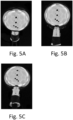
- Figs. 5A-5C show example images taken of the spherical light probe 31 using cameras of the scanner apparatus from different perspectives.
- the black dots represent camera openings.
- Fig. 6 is a diagram illustrating the differential rendering process at step 21 of Fig. 1 .
- a light probe model 60 for example in form of a mesh and a normal map as explained above, parameters 61 illustrating the camera, i.e. view parameters as discussed above, and a light model 62 in the form of a cube map, where pixels of the cube map represent the brightness of the illumination, are provided.
- the parameters may be initialized to random or predefined starting values, for example based on the knowledge of the general form of the light probe and arrangement of the camera, as explained above.
- a differential renderer 63 based on the parameters then generates a rendered image 64, which is compared to the actual captured image 65, which are used as reference images (for example the images of Figs 5A-5C ). Based on the comparison, an overall loss is defined, for example an overall loss composed of a fitting loss and regularization loss as explained above. Based on the gradient of the loss depending on the parameters, the parameters are then updated, and the method is repeated.
- Fig. 7 shows a more detailed diagram of a method according to an embodiment.
- the method starts at step 70.
- a low resolution light model is initialized, i.e. certain start parameters are used, e.g. random pixel values for a 2D light model or predefined pixel values.
- images corresponding to image 64 of Fig. 6
- these are compared to reference images (images of Fig. 5A-5C or image 65 of Fig. 6 ), and the loss functions explained above are evaluated. Based on the loss function, at 75 the parameters are updated using backpropagation.
- step 76 it is evaluated if a predetermined number of iterations has been reached or if the parameters have converged, for example that a change of the parameters in step 75 is below a predefined threshold. If this is not the case, step 73 to 75 are repeated for another iteration. If this is the case, at step 77 the method includes checking if a target resolution of the light model has been reached. If this not the case, at step 72 the resolution is increased, which corresponds to performing then a next group of iterations (73 to 76) with a higher resolution. If the target resolution is reached, the method ends at step 77.
- Fig. 8 The increasing of the resolution is illustrated in Fig. 8 .
- Fig. 8 different resolutions for three groups of iterations are shown.
- the light model is improved from an essentially randomly initialized model 80 via some intermediate model 81 to a model 82 (all models represented as cube maps).
- the model 82 in step 76 it is found that the model has converged, or a predetermined number of iterations is reached, but in step 77 it is found that the target resolution is not reached. Therefore, then the resolution is increased, where the parameters of model 82 are used as a starting point for a model 83 with increased resolution.
- pixels of model 82 may be multiplied, such that as a starting point for example for a resolution 4x as high each pixel of model 82 is converted into 4 pixels (2 x 2) having the same value as the original pixel in model 83, additional pixels may be obtained by interpolation like bilinear interpolation. Essentially and conventional upscaling method may be used. With this model, then further iterations are performed until a model 84 is reached, at which the answer at step 76 is yes but the answer at step 77 of Fig. 7 is again no.
- the resolution is increased again to arrive at a model 85, which is then optimized to arrive at an optimized model 86, at which then in this example both in step 76 and 77 the answer is yes, and the method is terminated. While three different resolutions are illustrated in Fig. 8 , in other embodiments more different resolutions may be used, or only two different resolutions are used.
- Fig. 9A illustrates an example for a rendered image using the techniques discussed herein, where the image of Fig. 9A is rendered in a perspective, i.e. viewing direction, corresponding to the image of Fig. 5A .
- the rendered image well coincides with the actual image.
- Fig. 9B shows a corresponding light model as a cube map (corresponding to light model 86).
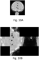
- Fig. 10A shows a reference image with a conventional method, for example as described by Debevec et al. cited above where an ideal spherical light probe is assumed.
- Fig. 10B shows a corresponding light model.
- both in the image of Fig. 10A and in the light model of Fig. 10B there are disturbances like distortions or jumps, which do not exist in the model of Fig. 9B .
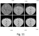
- Fig. 11 shows images rendered over a plurality of iterations, from an essentially randomly initialized first image 1100A over intermediate images 1100B-1100E to a final image 1100F.
Landscapes
- Engineering & Computer Science (AREA)
- Computer Graphics (AREA)
- Physics & Mathematics (AREA)
- General Physics & Mathematics (AREA)
- Theoretical Computer Science (AREA)
- Processing Or Creating Images (AREA)
Priority Applications (1)
| Application Number | Priority Date | Filing Date | Title |
|---|---|---|---|
| EP23175497.9A EP4468248A1 (de) | 2023-05-25 | 2023-05-25 | Verfahren und vorrichtung zur bestimmung des beleuchtungszustands einer abtastvorrichtung |
Applications Claiming Priority (1)
| Application Number | Priority Date | Filing Date | Title |
|---|---|---|---|
| EP23175497.9A EP4468248A1 (de) | 2023-05-25 | 2023-05-25 | Verfahren und vorrichtung zur bestimmung des beleuchtungszustands einer abtastvorrichtung |
Publications (1)
| Publication Number | Publication Date |
|---|---|
| EP4468248A1 true EP4468248A1 (de) | 2024-11-27 |
Family
ID=86603942
Family Applications (1)
| Application Number | Title | Priority Date | Filing Date |
|---|---|---|---|
| EP23175497.9A Withdrawn EP4468248A1 (de) | 2023-05-25 | 2023-05-25 | Verfahren und vorrichtung zur bestimmung des beleuchtungszustands einer abtastvorrichtung |
Country Status (1)
| Country | Link |
|---|---|
| EP (1) | EP4468248A1 (de) |
Citations (5)
| Publication number | Priority date | Publication date | Assignee | Title |
|---|---|---|---|---|
| US6628298B1 (en) | 1998-07-17 | 2003-09-30 | The Regents Of The University Of California | Apparatus and method for rendering synthetic objects into real scenes using measurements of scene illumination |
| WO2016135078A1 (en) | 2015-02-23 | 2016-09-01 | Fittingbox | Process and method for real-time physically accurate and realistic-looking glasses try-on |
| WO2017174525A1 (de) | 2016-04-04 | 2017-10-12 | Carl Zeiss Vision International Gmbh | Verfahren und vorrichtung zum bestimmen von parametern zur brillenanpassung |
| US10121451B2 (en) | 2015-10-22 | 2018-11-06 | Abl Ip Holding Llc | Ambient light probe |
| US11043025B2 (en) | 2018-09-28 | 2021-06-22 | Arizona Board Of Regents On Behalf Of Arizona State University | Illumination estimation for captured video data in mixed-reality applications |
-
2023
- 2023-05-25 EP EP23175497.9A patent/EP4468248A1/de not_active Withdrawn
Patent Citations (5)
| Publication number | Priority date | Publication date | Assignee | Title |
|---|---|---|---|---|
| US6628298B1 (en) | 1998-07-17 | 2003-09-30 | The Regents Of The University Of California | Apparatus and method for rendering synthetic objects into real scenes using measurements of scene illumination |
| WO2016135078A1 (en) | 2015-02-23 | 2016-09-01 | Fittingbox | Process and method for real-time physically accurate and realistic-looking glasses try-on |
| US10121451B2 (en) | 2015-10-22 | 2018-11-06 | Abl Ip Holding Llc | Ambient light probe |
| WO2017174525A1 (de) | 2016-04-04 | 2017-10-12 | Carl Zeiss Vision International Gmbh | Verfahren und vorrichtung zum bestimmen von parametern zur brillenanpassung |
| US11043025B2 (en) | 2018-09-28 | 2021-06-22 | Arizona Board Of Regents On Behalf Of Arizona State University | Illumination estimation for captured video data in mixed-reality applications |
Non-Patent Citations (11)
| Title |
|---|
| D. AZINOVIC ET AL.: "Inverse Path Tracing for Joint Material and Lighting Estimation", ARXIV: 1903.07145, 2019 |
| DEBEVEC PAUL ED - ASSOCIATION FOR COMPUTING MACHINERY: "Rendering synthetic objects into real scenes bridging traditional and image-based graphics with global illumination and high dynamic range photography", COMPUTER GRAPHICS PROCEEDINGS. SIGGRAPH 99; [COMPUTER GRAPHICS PROCEEDINGS. SIGGRAPH], ACM ? - NEW YORK, NY, USA, 1515 BROADWAY, 17TH FLOOR NEW YORK, NY 10036 USA, 24 July 1998 (1998-07-24), pages 189 - 198, XP059029271, ISBN: 978-0-201-48560-8, DOI: 10.1145/280814.280864 * |
| FUJUN LUAN ET AL: "Unified Shape and SVBRDF Recovery using Differentiable Monte Carlo Rendering", COMPUTER GRAPHICS FORUM : JOURNAL OF THE EUROPEAN ASSOCIATION FOR COMPUTER GRAPHICS, WILEY-BLACKWELL, OXFORD, vol. 40, no. 4, 15 July 2021 (2021-07-15), pages 101 - 113, XP071489359, ISSN: 0167-7055, DOI: 10.1111/CGF.14344 * |
| G. NIETO ET AL.: "Robust Point Light Estimation Using Differentiable Rendering", ARXIV: 1812.04857, 2018 |
| GR\'EGOIRE NIETO ET AL: "Robust Point Light Source Estimation Using Differentiable Rendering", ARXIV.ORG, CORNELL UNIVERSITY LIBRARY, 201 OLIN LIBRARY CORNELL UNIVERSITY ITHACA, NY 14853, 12 December 2018 (2018-12-12), XP080992142 * |
| HONG-XING YU ET AL: "Accidental Light Probes", ARXIV.ORG, CORNELL UNIVERSITY LIBRARY, 201 OLIN LIBRARY CORNELL UNIVERSITY ITHACA, NY 14853, 5 April 2023 (2023-04-05), XP091476332 * |
| HONG-XING YU ET AL: "Supplementary Material for Accidental Light Probes", 5 April 2023 (2023-04-05), pages 1 - 5, XP093092131, Retrieved from the Internet <URL:https://kovenyu.com/alp/static/yu2023alp_supp.pdf> [retrieved on 20231016] * |
| JOHANNES KOHLER ET AL.: "A full spherical device for simultaneous geometry and reflectance acquisition", 2013 IEEE WORKSHOP ON APPLICATIONS OF COMPUTER VISION |
| KATO, H ET AL.: "Differentiable Rendering: A Survey", ARXIV: 2006.12057 V2, 2020 |
| KRONANDER, J ET AL.: "Photorealistic rendering of mixed reality scenes", COMPUTER GRAPHICS FORUM, 2015 |
| RIVIERE JÉRÉMY ET AL: "Single-shot high-quality facial geometry and skin appearance capture", ACM TRANSACTIONS ON GRAPHICS, ACM, NY, US, vol. 39, no. 4, 8 July 2020 (2020-07-08), pages 81:1 - 81:12, XP059023313, ISSN: 0730-0301, DOI: 10.1145/3386569.3392464 * |
Similar Documents
| Publication | Publication Date | Title |
|---|---|---|
| US20240169658A1 (en) | Systems and Methods for Reconstructing Scenes to Disentangle Light and Matter Fields | |
| Meilland et al. | 3d high dynamic range dense visual slam and its application to real-time object re-lighting | |
| KR102287472B1 (ko) | 인공조명 사진을 이용한 3차원 객체 획득 방법 및 그 장치 | |
| CN110599578A (zh) | 一种真实感三维彩色纹理重建方法 | |
| US20030197806A1 (en) | Single lens 3D camera | |
| AU2003298666A1 (en) | Reality-based light environment for digital imaging in motion pictures | |
| US6963671B2 (en) | Method for determining distances to a surface from a range image | |
| US9147279B1 (en) | Systems and methods for merging textures | |
| CN119165652A (zh) | 一种光学镜头高精度三维重构方法与系统 | |
| JP2003115042A (ja) | 3次元形状モデルの評価方法および生成方法並びに装置 | |
| CN119850853B (zh) | 一种全自动、快速、高精度三维重建方法及系统 | |
| JP2001236522A (ja) | 画像処理装置 | |
| Puerta et al. | Photogrammetry as an engineering design tool | |
| CN118411398A (zh) | 一种小型瓷器三维几何与光学材质重建方法与装置 | |
| CN112862736A (zh) | 一种基于点的实时三维重建与优化方法 | |
| Lin et al. | Vision system for fast 3-D model reconstruction | |
| US20030197708A1 (en) | Method for generating a textured range image | |
| CN119251430A (zh) | 一种基于点云数据的虚拟场景构建方法、介质及设备 | |
| KR100681320B1 (ko) | 헬름홀츠 교환조건으로부터 유도되는 편미분 방정식의레벨셋 풀이 방법을 이용한 물체의 3차원 형상 모델링 방법 | |
| Kang et al. | View-dependent scene appearance synthesis using inverse rendering from light fields | |
| EP4468248A1 (de) | Verfahren und vorrichtung zur bestimmung des beleuchtungszustands einer abtastvorrichtung | |
| JP2004252603A (ja) | 三次元データ処理方法 | |
| CN120088406A (zh) | 一种折射率自适应的透明物体重建方法 | |
| JP7508673B2 (ja) | コンピュータビジョン方法およびシステム | |
| Petrovska et al. | Impact of Rain on 3D Reconstruction with Multi-View Stereo, Neural Radiance Fields and Gaussian Splatting |
Legal Events
| Date | Code | Title | Description |
|---|---|---|---|
| PUAI | Public reference made under article 153(3) epc to a published international application that has entered the european phase |
Free format text: ORIGINAL CODE: 0009012 |
|
| STAA | Information on the status of an ep patent application or granted ep patent |
Free format text: STATUS: THE APPLICATION HAS BEEN PUBLISHED |
|
| AK | Designated contracting states |
Kind code of ref document: A1 Designated state(s): AL AT BE BG CH CY CZ DE DK EE ES FI FR GB GR HR HU IE IS IT LI LT LU LV MC ME MK MT NL NO PL PT RO RS SE SI SK SM TR |
|
| STAA | Information on the status of an ep patent application or granted ep patent |
Free format text: STATUS: THE APPLICATION IS DEEMED TO BE WITHDRAWN |
|
| 18D | Application deemed to be withdrawn |
Effective date: 20250528 |