EP4468446A1 - Bloc-batterie - Google Patents
Bloc-batterie Download PDFInfo
- Publication number
- EP4468446A1 EP4468446A1 EP23760330.3A EP23760330A EP4468446A1 EP 4468446 A1 EP4468446 A1 EP 4468446A1 EP 23760330 A EP23760330 A EP 23760330A EP 4468446 A1 EP4468446 A1 EP 4468446A1
- Authority
- EP
- European Patent Office
- Prior art keywords
- battery
- bms
- battery pack
- wireless transmission
- cell
- Prior art date
- Legal status (The legal status is an assumption and is not a legal conclusion. Google has not performed a legal analysis and makes no representation as to the accuracy of the status listed.)
- Pending
Links
Images




Classifications
-
- H—ELECTRICITY
- H01—ELECTRIC ELEMENTS
- H01M—PROCESSES OR MEANS, e.g. BATTERIES, FOR THE DIRECT CONVERSION OF CHEMICAL ENERGY INTO ELECTRICAL ENERGY
- H01M10/00—Secondary cells; Manufacture thereof
- H01M10/42—Methods or arrangements for servicing or maintenance of secondary cells or secondary half-cells
- H01M10/4207—Methods or arrangements for servicing or maintenance of secondary cells or secondary half-cells for several batteries or cells simultaneously or sequentially
-
- H—ELECTRICITY
- H01—ELECTRIC ELEMENTS
- H01M—PROCESSES OR MEANS, e.g. BATTERIES, FOR THE DIRECT CONVERSION OF CHEMICAL ENERGY INTO ELECTRICAL ENERGY
- H01M10/00—Secondary cells; Manufacture thereof
- H01M10/42—Methods or arrangements for servicing or maintenance of secondary cells or secondary half-cells
-
- H—ELECTRICITY
- H01—ELECTRIC ELEMENTS
- H01M—PROCESSES OR MEANS, e.g. BATTERIES, FOR THE DIRECT CONVERSION OF CHEMICAL ENERGY INTO ELECTRICAL ENERGY
- H01M10/00—Secondary cells; Manufacture thereof
- H01M10/42—Methods or arrangements for servicing or maintenance of secondary cells or secondary half-cells
- H01M10/425—Structural combination with electronic components, e.g. electronic circuits integrated to the outside of the casing
-
- H—ELECTRICITY
- H01—ELECTRIC ELEMENTS
- H01M—PROCESSES OR MEANS, e.g. BATTERIES, FOR THE DIRECT CONVERSION OF CHEMICAL ENERGY INTO ELECTRICAL ENERGY
- H01M10/00—Secondary cells; Manufacture thereof
- H01M10/42—Methods or arrangements for servicing or maintenance of secondary cells or secondary half-cells
- H01M10/425—Structural combination with electronic components, e.g. electronic circuits integrated to the outside of the casing
- H01M10/4257—Smart batteries, e.g. electronic circuits inside the housing of the cells or batteries
-
- H—ELECTRICITY
- H01—ELECTRIC ELEMENTS
- H01M—PROCESSES OR MEANS, e.g. BATTERIES, FOR THE DIRECT CONVERSION OF CHEMICAL ENERGY INTO ELECTRICAL ENERGY
- H01M10/00—Secondary cells; Manufacture thereof
- H01M10/42—Methods or arrangements for servicing or maintenance of secondary cells or secondary half-cells
- H01M10/48—Accumulators combined with arrangements for measuring, testing or indicating the condition of cells, e.g. the level or density of the electrolyte
-
- H—ELECTRICITY
- H01—ELECTRIC ELEMENTS
- H01M—PROCESSES OR MEANS, e.g. BATTERIES, FOR THE DIRECT CONVERSION OF CHEMICAL ENERGY INTO ELECTRICAL ENERGY
- H01M10/00—Secondary cells; Manufacture thereof
- H01M10/42—Methods or arrangements for servicing or maintenance of secondary cells or secondary half-cells
- H01M10/48—Accumulators combined with arrangements for measuring, testing or indicating the condition of cells, e.g. the level or density of the electrolyte
- H01M10/482—Accumulators combined with arrangements for measuring, testing or indicating the condition of cells, e.g. the level or density of the electrolyte for several batteries or cells simultaneously or sequentially
-
- H—ELECTRICITY
- H01—ELECTRIC ELEMENTS
- H01M—PROCESSES OR MEANS, e.g. BATTERIES, FOR THE DIRECT CONVERSION OF CHEMICAL ENERGY INTO ELECTRICAL ENERGY
- H01M10/00—Secondary cells; Manufacture thereof
- H01M10/42—Methods or arrangements for servicing or maintenance of secondary cells or secondary half-cells
- H01M10/48—Accumulators combined with arrangements for measuring, testing or indicating the condition of cells, e.g. the level or density of the electrolyte
- H01M10/486—Accumulators combined with arrangements for measuring, testing or indicating the condition of cells, e.g. the level or density of the electrolyte for measuring temperature
-
- H—ELECTRICITY
- H01—ELECTRIC ELEMENTS
- H01M—PROCESSES OR MEANS, e.g. BATTERIES, FOR THE DIRECT CONVERSION OF CHEMICAL ENERGY INTO ELECTRICAL ENERGY
- H01M50/00—Constructional details or processes of manufacture of the non-active parts of electrochemical cells other than fuel cells, e.g. hybrid cells
- H01M50/20—Mountings; Secondary casings or frames; Racks, modules or packs; Suspension devices; Shock absorbers; Transport or carrying devices; Holders
- H01M50/284—Mountings; Secondary casings or frames; Racks, modules or packs; Suspension devices; Shock absorbers; Transport or carrying devices; Holders with incorporated circuit boards, e.g. printed circuit boards [PCB]
-
- H—ELECTRICITY
- H01—ELECTRIC ELEMENTS
- H01M—PROCESSES OR MEANS, e.g. BATTERIES, FOR THE DIRECT CONVERSION OF CHEMICAL ENERGY INTO ELECTRICAL ENERGY
- H01M10/00—Secondary cells; Manufacture thereof
- H01M10/42—Methods or arrangements for servicing or maintenance of secondary cells or secondary half-cells
- H01M10/425—Structural combination with electronic components, e.g. electronic circuits integrated to the outside of the casing
- H01M2010/4271—Battery management systems including electronic circuits, e.g. control of current or voltage to keep battery in healthy state, cell balancing
-
- H—ELECTRICITY
- H01—ELECTRIC ELEMENTS
- H01M—PROCESSES OR MEANS, e.g. BATTERIES, FOR THE DIRECT CONVERSION OF CHEMICAL ENERGY INTO ELECTRICAL ENERGY
- H01M10/00—Secondary cells; Manufacture thereof
- H01M10/42—Methods or arrangements for servicing or maintenance of secondary cells or secondary half-cells
- H01M10/425—Structural combination with electronic components, e.g. electronic circuits integrated to the outside of the casing
- H01M2010/4278—Systems for data transfer from batteries, e.g. transfer of battery parameters to a controller, data transferred between battery controller and main controller
-
- H—ELECTRICITY
- H01—ELECTRIC ELEMENTS
- H01M—PROCESSES OR MEANS, e.g. BATTERIES, FOR THE DIRECT CONVERSION OF CHEMICAL ENERGY INTO ELECTRICAL ENERGY
- H01M50/00—Constructional details or processes of manufacture of the non-active parts of electrochemical cells other than fuel cells, e.g. hybrid cells
- H01M50/20—Mountings; Secondary casings or frames; Racks, modules or packs; Suspension devices; Shock absorbers; Transport or carrying devices; Holders
- H01M50/204—Racks, modules or packs for multiple batteries or multiple cells
- H01M50/207—Racks, modules or packs for multiple batteries or multiple cells characterised by their shape
- H01M50/211—Racks, modules or packs for multiple batteries or multiple cells characterised by their shape adapted for pouch cells
-
- Y—GENERAL TAGGING OF NEW TECHNOLOGICAL DEVELOPMENTS; GENERAL TAGGING OF CROSS-SECTIONAL TECHNOLOGIES SPANNING OVER SEVERAL SECTIONS OF THE IPC; TECHNICAL SUBJECTS COVERED BY FORMER USPC CROSS-REFERENCE ART COLLECTIONS [XRACs] AND DIGESTS
- Y02—TECHNOLOGIES OR APPLICATIONS FOR MITIGATION OR ADAPTATION AGAINST CLIMATE CHANGE
- Y02E—REDUCTION OF GREENHOUSE GAS [GHG] EMISSIONS, RELATED TO ENERGY GENERATION, TRANSMISSION OR DISTRIBUTION
- Y02E60/00—Enabling technologies; Technologies with a potential or indirect contribution to GHG emissions mitigation
- Y02E60/10—Energy storage using batteries
Definitions
- the present invention relates to a battery pack.
- Secondary batteries are rechargeable unlike primarily batteries, and also, the possibility of compact size and high capacity is high. Thus, recently, many studies on secondary batteries are being carried out. As technology development and demands for mobile devices increase, the demands for secondary batteries as energy sources are rapidly increasing.
- Rechargeable batteries are classified into coin type batteries, cylindrical type batteries, prismatic type batteries, and pouch type batteries according to a shape of a battery case.
- an electrode assembly mounted in a battery case is a chargeable and dischargeable power generating device having a structure in which an electrode and a separator are stacked.
- Secondary batteries are attracting much attention as energy sources for power devices such as electric bicycle, electric vehicles, and hybrid electric vehicles as well as mobile devices such as mobile phones, digital cameras, and laptops.
- a small-sized battery pack in which one battery cell is packed is used for small devices such as mobile phones and cameras, but a battery pack in which two or more battery cells are connected in parallel and/or series is used for medium and large-sized devices such as laptop computers and electric vehicles.
- the number of battery cells provided in the battery pack may be variously set according to a required output voltage or charge/discharge capacity.
- the battery pack is configured by connecting a plurality of battery cells in series/parallel, a method in which a battery module constituted by at least one battery cell is configured first, and other components are added using the at least one battery module to constitute the battery pack is common.
- a battery is constituted by cells, which are the smallest units, and since a pouch-type cell requires structural rigidity, a module including a plurality of cells is provided as an intermediate unit, and then, a plurality of modules are provided to constitute a pack.
- each of the modules in the pack has to be perform various signal sensing (voltage/temperature) through a battery management system (BMS), the modules are electrically connected to the BMS.
- the corresponding component is connected through a long wire called a low voltage (LV) line.
- LV low voltage
- One aspect of the present invention is to provide a battery pack capable of reducing an occurrence of a safety risk.
- a battery pack may be a battery pack including a battery module, wherein the battery module may include: a cell stack in which a plurality of battery cells are stacked; a flexible circuit board configured to transmit information of the battery cell; a module housing configured to accommodate the cell stack and the flexible circuit board; a wireless transmission battery management system (BMS) configured to receive the information of the battery cell from the flexible circuit board; and a BMS accommodation part provided outside the module housing to accommodate the wireless transmission BMS.
- BMS wireless transmission battery management system
- the battery module may include the wireless transmission BMS that receives the information of the battery cell disposed therein and the BMS accommodation part in which the wireless transmission BMS is accommodated so that the information of the battery cell is wirelessly transmitted.
- the wire such as the low voltage (LW) that connects the BMS inside the battery pack may not be used to reduce the occurrence of the safety risk. That is, the bundle of the wires such as the LW connecting the BMS may be removed to prevent the risk of the short circuit caused by applying the current and voltage to the bundle of the wires such as the LW.
- LW low voltage
- the modularization since the BMS accommodation part is coupled to the outside of the module housing by the coupling means, the modularization may be easy, and the accessibility and repair in the event of the breakdown of the wireless transmission BMS accommodated in the BMS accommodation part may be facilitated.
- the BMS accommodation part may be mounted on the endplate of the module housing and be mounted in the mounting groove recessed from the endplate toward the surplus internal space of the module housing to minimize the wasted space inside the battery module.
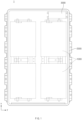
- FIG. 1 is a projected plan view illustrating an example of a battery pack according to an embodiment of the present invention
- FIG. 2 is a perspective view illustrating a battery module in the battery pack according to an embodiment of the present invention
- FIG. 3 is an exploded perspective view illustrating the battery module in the battery pack according to an embodiment of the present invention.
- a battery pack 1 is a battery pack 1 including a battery module 1000, and the battery module 1000 includes a cell stack 200 in which a plurality of battery cells 210 are stacked, a flexible circuit board 700 that transmits information of the plurality of battery cells 210, a module housing 100 accommodating the cell stack 200 and the flexible circuit board 700, a wireless transmission BMS 600 receiving the information of the battery cell 210 from the flexible circuit board 700, and a BMS accommodation part H in which the wireless transmission BMS 600 is accommodated.
- the battery pack 1 may further include a wireless receiving BMS 3000 and a pack case 2000.
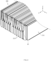
- FIG. 4 is a perspective view illustrating the cell stack in the battery module of the battery pack according to an embodiment of the present invention
- FIG. 5 is a side view illustrating the battery cell 210 in the battery module of the battery pack according to an embodiment of the present invention
- FIG. 6 is a side view illustrating a main part of the battery cell in the battery module of the battery pack according to an embodiment of the present invention.
- the cell stack 200 may have a shape in which the plurality of battery cells 210 are stacked.
- the battery cell 210 may include an electrode assembly and a pouch 211 accommodating the electrode assembly therein.
- the electrode assembly may be a chargeable and dischargeable power generating element, and electrodes and separators may be alternately stacked in the electrode assembly.
- the electrodes may include a positive electrode and a negative electrode, and the positive electrode, the separators, and the negative electrode may be alternately stacked.
- each of the separators separates the positive electrode from the negative electrode to electrically insulate the positive electrode from the negative electrode.
- the battery cell 210 may further include an electrode lead 212 having one side connected to the electrode of the electrode assembly and the other side extending to the outside of the pouch 211.
- the electrode lead 212 may extend to both sides.
- a surplus space R1 that is an empty space may be defined in an upper edge portion R of the battery cell 210.
- FIG. 4 when the plurality of battery cells 210 are stacked in a Y-axis direction that is a traverse direction to form the cell stack 200, a surplus space R1 that is an empty space may be defined in an upper edge portion R of the cell stack 200.
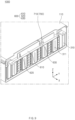
- FIG. 7 is a perspective view illustrating a main part of the battery module in the battery pack according to an embodiment of the present invention
- FIG. 8 is an exploded perspective view illustrating the main part of the battery module in the battery pack according to an embodiment of the present invention
- FIG. 9 is a perspective view illustrating a concept in which an endplate is removed from the battery module of the battery pack according to an embodiment of the present invention.
- FIG. 9 illustrates a state in which a state in which the BMS accommodation part is removed from convenience so as to clearly show a state in which the flexible circuit board is connected to the wireless transmission BMS 600.
- the wireless transmission battery management system (BMS) 600 may receive information of the battery cell 210 from the flexible circuit board 700.
- the wireless transmission BMS 600 may include a connection part 630 to which an end 710 of the flexible circuit board 700 is connected.
- the wireless transmission BMS 600 may include a wireless transmission part 620 that wirelessly transmits an information signal of the battery cells 210 received from the flexible circuit board 700.
- the wireless transmission BMS 600 may include a substrate 610 on which the connection part 630 and the wireless transmission part 620 are mounted.
- a fitting hole 611 may be defined in the substrate 610.
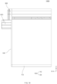
- FIG. 10 is a side view illustrating the main part of the battery module in the battery pack according to an embodiment of the present invention
- FIG. 11 is a side view illustrating the main part of the battery module in the battery pack according to an embodiment of the present invention.
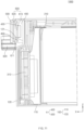
- the BMS accommodation part H may be provided outside the module housing 100 so that the wireless transmission BMS 600 is accommodated therein.
- the BMS accommodation part H may include an accommodation case 400 having an accommodation groove 410 that is opened to the outside of the module housing 100 to accommodate the wireless transmission BMS 600.
- the BMS accommodation part H may further include a cover 500 covering an opening of the accommodation groove 410.
- a coupling protrusion 420 may be disposed on the accommodation case 400, and a coupling hole 520 to which the coupling protrusion 420 is coupled may be defined in the cover 500.
- the cover 500 may be detachably coupled to the accommodation case 400.
- the wireless transmission BMS 600 accommodated in the accommodation case 400 may be easily replaced.
- the accommodation case 400 may be coupled to an outer portion of the module housing 100 through a coupling means 900.
- the accommodation case 400 may have a coupling hole 430 through which the coupling means 900 passes to be coupled.
- the coupling hole 430 may be defined in the coupling part 440 extending in the Y-axis direction, which is a width direction of the battery module 1000, in the accommodation case 400.
- the coupling means 900 may include, for example, a bolt 910 and a nut 920.
- the bolt 910 may have one side fixed to the module housing 100 and the other side extending to the outside of the module housing 100, and the nut 920 may be coupled to the other side of the bolt 910 after the bolt 910 is coupled to the coupling hole 430 of the accommodation case 400.
- the accommodation case 400 may be fixed to an outer portion of the module housing 100.
- the coupling means 900 may not be necessarily limited to the bolt 910 and the nut 920.
- the coupling means 900 may be a rivet or the like.
- the accommodation case 400 may further include a fitting protrusion 450 fitted into the fitting hole 611 of the substrate 610 in the wireless transmission BMS 600.
- the wireless transmission BMS 600 may be accommodated in the accommodation case 400 so as not to move.
- the module housing 100 may accommodate the cell stack 200 and the flexible circuit board 700.
- the module housing 100 may include a body 110 provided with a stack accommodation part 114, in which the cell stack 200 is accommodated, and having a tubular shape that is opened to both sides, and endplates 120 and 130 covering openings of the body 110.
- the BMS accommodation part H may be mounted on the endplate 120.
- the surplus space R1 that is an empty space may be defined.
- the endplate 120 may have a mounting groove 121 that is recessed into the module housing 100 to occupy the surplus space R1.
- the BMS accommodation part H may be accommodated in the mounting groove 121 and be mounted on the endplate 120.
- the endplates 120 and 130 may be provided in plurality to cover the openings defined at both sides of the body 110, respectively.
- the BMS accommodation part H may be mounted on one endplate 120 of the plurality of endplates 120 and 130.
- the plurality of endplates 120 and 130 may be disposed on front and rear surfaces of the body 110, and the BMS accommodation part H may be mounted on the endplate 120 disposed on the front surface of the body 110.
- the recessed mounting groove 121 may be defined by pressing the endplate 120 disposed on the front surface of the body 110.
- the endplate 120 disposed on the front surface of the body 110 may be sealed and welded to the body 110, the endplate 120 may have an advantage in terms of sealing and thermal propagation of the module.
- the body 110 may include a body 112, which is provided in a " " shape and opened to an upper side, and a top plate covering an upper portion 111 of the body 112.
- a gas discharge hole 113 may be defined in the body 110 so that an internal gas is discharged to the outside.
- the battery module 1000 may further include busbars 310 and 320.
- the electrode lead 212 of the battery cell 210 may be electrically connected to the busbars 310 and 320.
- the electrode lead 212 of the battery cell 210 may pass through the connection hole 311 of the busbars 310 and 320 and be connected to the busbars 310 and 320.
- the electrode lead 212 may be connected to the busbars 310 and 320 and be electrically connected to terminals 810 and 820.
- the busbars 310 and 320 may include an insulating part made of an insulating material and a conductive part made of a material through which electricity is conducted.
- the conductive part may be a portion connecting a peripheral portion of the connection hole and each of the terminals 810 and 820.
- the flexible circuit board 700 may transfer information of the battery cell 210 to the wireless transmission BMS 600.
- the flexible circuit board 700 may transfer an information signal of the battery cell 210 to the wireless transmission BMS 600.
- the information signal of the battery cell 210 may be at least one or more of a remaining capacity, a voltage, and a temperature signal of the battery cell 210.
- the flexible circuit board 700 may be, for example, a flexible printed circuit board (FPCB).
- FPCB flexible printed circuit board
- the flexible circuit board 700 may include a measurement sensor, which measures a voltage and current, and be connected to the busbars 310 and 320 to measure the voltage and current flowing inside the busbars 310 and 320.
- the electrode lead 212 of the battery cell 210 may be connected to the busbars 310 and 320 to measure the voltage and current flowing inside the busbars 310 and 320, thereby measuring amounts of voltage and current flowing into the battery cell 210.
- the flexible circuit board 700 may include a temperature sensor, and a portion at which the temperature sensor is disposed may be in contact with the cell stack 200 to measure the temperature of the battery cell 210.
- an end 710 of the flexible circuit board 700 may further extend to be connected to the wireless transmission BMS 600.
- a wireless receiving BMS 3000 may wirelessly receive the information signal of the battery cell 210 from the wireless transmitting BMS 600.
- the wireless receiving BMS 3000 may determine a state of the battery cell 210 through the received information signal of the battery cell 210 and control charging and discharging of the battery cell 210 so that the battery is maintained in an appropriate state.
- the information signal of the battery cell 210 may be at least one of the remaining capacity, the voltage, or the temperature signals of the battery cell 210.
- the pack case 2000 may accommodate the battery module 1000 therein.
- the battery module 1000 may be provided in plurality and accommodated inside the pack case 2000.
- the wireless receiving BMS 3000 may be installed inside the pack case 2000 to receive the information signals of the battery cells 210 disposed in each battery module 1000 from the wireless transmission BMS 600 provided in each of the plurality of battery modules 1000.
- the battery module 1000 in the battery pack 1 may include the wireless transmission BMS 600 receiving the information of the battery cell 210 disposed inside the battery module 1000 and the BMS accommodation part, in which the wireless transmission BMS 600 is accommodated, to wirelessly transmit the information of the battery cell 210.
- the low voltage (LW) connecting the battery management system BMS inside the battery pack may not be used to reduce the occurrence of the safety risk. That is, the bundle of the wires such as the LW connecting the BMS may be removed to prevent the risk of the short circuit caused by applying the current and voltage to the bundle of the wires such as the LW.
- the BMS accommodation part H may be coupled to the outside of the module housing 100 by means of coupling means to facilitate modularization, and when the wireless transmission BMS 600 accommodated in the BMS accommodation part H is broken, the accessibility and repair may be easy, and peripheral steel parts that interfere with communication of the wireless transmission BMS 600 may be minimized.
- the BMS accommodation part H may be mounted on the endplate 120 of the module housing 100 and also may be mounted in the mounting groove 121 recessed from the endplate 120 toward the internal surplus space R1 of the module housing 100 to minimize a space wasted in the form of a terrace of the battery cell 210 defining the surplus space R1 inside the battery module 1000.
Landscapes
- Engineering & Computer Science (AREA)
- Chemical & Material Sciences (AREA)
- Chemical Kinetics & Catalysis (AREA)
- Electrochemistry (AREA)
- General Chemical & Material Sciences (AREA)
- Manufacturing & Machinery (AREA)
- Microelectronics & Electronic Packaging (AREA)
- Battery Mounting, Suspending (AREA)
- Connection Of Batteries Or Terminals (AREA)
Applications Claiming Priority (2)
| Application Number | Priority Date | Filing Date | Title |
|---|---|---|---|
| KR1020220023960A KR20230126592A (ko) | 2022-02-23 | 2022-02-23 | 전지 팩 |
| PCT/KR2023/002287 WO2023163456A1 (fr) | 2022-02-23 | 2023-02-16 | Bloc-batterie |
Publications (2)
| Publication Number | Publication Date |
|---|---|
| EP4468446A1 true EP4468446A1 (fr) | 2024-11-27 |
| EP4468446A4 EP4468446A4 (fr) | 2025-07-09 |
Family
ID=87766386
Family Applications (1)
| Application Number | Title | Priority Date | Filing Date |
|---|---|---|---|
| EP23760330.3A Pending EP4468446A4 (fr) | 2022-02-23 | 2023-02-16 | Bloc-batterie |
Country Status (6)
| Country | Link |
|---|---|
| US (1) | US20260038890A1 (fr) |
| EP (1) | EP4468446A4 (fr) |
| JP (1) | JP2025508797A (fr) |
| KR (1) | KR20230126592A (fr) |
| CN (1) | CN118743076A (fr) |
| WO (1) | WO2023163456A1 (fr) |
Families Citing this family (1)
| Publication number | Priority date | Publication date | Assignee | Title |
|---|---|---|---|---|
| CN119764714B (zh) * | 2024-12-23 | 2026-01-30 | 惠州亿纬锂能股份有限公司 | 电池包、电池包组装方法及用电装置 |
Family Cites Families (16)
| Publication number | Priority date | Publication date | Assignee | Title |
|---|---|---|---|---|
| US20140170679A1 (en) | 2011-03-07 | 2014-06-19 | James Stewart Aitchison | Method and system for cell detection and analysis |
| JP5870666B2 (ja) * | 2011-12-09 | 2016-03-01 | 日産自動車株式会社 | 電池モジュール |
| CH711926A1 (de) * | 2015-12-17 | 2017-06-30 | Greenteg Ag | Messaufbau zur Funktionskontrolle von wiederaufladbaren Batterien. |
| CN108886176B (zh) * | 2016-04-18 | 2022-03-08 | 罗伯特·博世有限公司 | 低剖面传感器以及包括其的电化学电池 |
| KR102340898B1 (ko) * | 2018-03-30 | 2021-12-16 | 주식회사 엘지에너지솔루션 | 조립성이 향상된 버스바 프레임을 구비한 배터리 모듈 |
| HUE063836T2 (hu) * | 2018-06-06 | 2024-02-28 | Samsung Sdi Co Ltd | Akkumulátorrendszer rendellenes állapotainak észlelése |
| EP3895232A1 (fr) * | 2018-12-14 | 2021-10-20 | Koninklijke Philips N.V. | Système pour améliorer la sécurité et la fiabilité d'un bloc-batterie lithium-ion (li-ion) |
| KR102550319B1 (ko) * | 2019-02-01 | 2023-07-04 | 주식회사 엘지에너지솔루션 | 배터리 시스템 및 슬레이브 배터리 관리 시스템 |
| DE102019209585B3 (de) * | 2019-07-01 | 2020-12-31 | Volkswagen Aktiengesellschaft | Fahrzeugbatterie für ein Kraftfahrzeug |
| KR102772766B1 (ko) * | 2019-08-30 | 2025-02-24 | 주식회사 엘지에너지솔루션 | 전지 모듈 및 이를 포함하는 전지팩 |
| KR102839448B1 (ko) * | 2019-09-27 | 2025-07-25 | 주식회사 엘지에너지솔루션 | 액체 감지 연성 인쇄 회로 기판을 포함하는 전지 모듈 |
| JP6996574B2 (ja) * | 2020-01-06 | 2022-01-17 | 株式会社デンソー | 電池パック |
| JP2021112057A (ja) * | 2020-01-14 | 2021-08-02 | 株式会社オートネットワーク技術研究所 | 電池管理システム |
| KR102812829B1 (ko) * | 2020-03-05 | 2025-05-23 | 주식회사 엘지에너지솔루션 | 이동 및 조립이 편의성이 증대된 구조 및 안전성이 향상된 구조를 갖는 배터리 팩 |
| KR102381583B1 (ko) * | 2020-04-24 | 2022-04-04 | 에너테크인터내셔널 주식회사 | 모니터링 장치를 구비하는 전기자동차용 배터리 모듈 |
| KR102866740B1 (ko) * | 2020-08-11 | 2025-09-29 | 주식회사 엘지에너지솔루션 | 조립성이 개선된 배터리 모듈 및 이를 포함하는 배터리 팩 |
-
2022
- 2022-02-23 KR KR1020220023960A patent/KR20230126592A/ko active Pending
-
2023
- 2023-02-16 WO PCT/KR2023/002287 patent/WO2023163456A1/fr not_active Ceased
- 2023-02-16 CN CN202380023210.XA patent/CN118743076A/zh active Pending
- 2023-02-16 US US18/840,809 patent/US20260038890A1/en active Pending
- 2023-02-16 EP EP23760330.3A patent/EP4468446A4/fr active Pending
- 2023-02-16 JP JP2024549606A patent/JP2025508797A/ja active Pending
Also Published As
| Publication number | Publication date |
|---|---|
| WO2023163456A1 (fr) | 2023-08-31 |
| JP2025508797A (ja) | 2025-04-10 |
| CN118743076A (zh) | 2024-10-01 |
| KR20230126592A (ko) | 2023-08-30 |
| EP4468446A4 (fr) | 2025-07-09 |
| US20260038890A1 (en) | 2026-02-05 |
Similar Documents
| Publication | Publication Date | Title |
|---|---|---|
| EP2064759B1 (fr) | Interface de module de batterie | |
| EP2388845B1 (fr) | Bloc-batteries | |
| KR101815876B1 (ko) | 과전류 방지장치를 포함한 배터리 팩 | |
| EP1807900B1 (fr) | Element de mesure de la tension et de la temperature des piles dans un bloc-piles | |
| EP3836247A1 (fr) | Module de batterie, bloc-batterie comprenant un tel module de batterie et véhicule comprenant un tel bloc-batterie | |
| CN101488595B (zh) | 二次电池模块 | |
| EP4030515B1 (fr) | Module de batterie | |
| US20250192375A1 (en) | Battery and electrical apparatus | |
| WO2023197768A1 (fr) | Appareil d'alimentation électrique et appareil électrique | |
| CN118299767A (zh) | 电池组和用电设备 | |
| EP4468446A1 (fr) | Bloc-batterie | |
| CN110474012B (zh) | 电池和电池系统 | |
| CN119208851A (zh) | 电池装置、储能装置及用电装置 | |
| KR20190060963A (ko) | 이차전지 | |
| JP7566029B2 (ja) | バッテリーモジュール、それを含むバッテリーパック及び自動車 | |
| EP4503313A1 (fr) | Module de batterie | |
| CN223743793U (zh) | 电池单体、电池装置、储能装置及用电装置 | |
| EP4164047B1 (fr) | Module de batterie comprenant une unité de détection sous forme courbée et dispositif électronique le comprenant | |
| US20250201952A1 (en) | Battery assembly | |
| KR20200092672A (ko) | 이차 전지 및 이를 포함하는 이차 전지 모듈 | |
| KR20230164598A (ko) | 전지 모듈 | |
| KR20260019278A (ko) | 압전 센서를 포함하는 배터리 모듈 및 이를 포함하는 배터리 팩 | |
| KR20240097673A (ko) | 배터리 어셈블리 | |
| KR20230057270A (ko) | 원통형 전지 셀과 온도 센서를 포함하는 전지 시스템 및 그 설치 방법 | |
| KR20220091290A (ko) | 배터리 팩 |
Legal Events
| Date | Code | Title | Description |
|---|---|---|---|
| STAA | Information on the status of an ep patent application or granted ep patent |
Free format text: STATUS: THE INTERNATIONAL PUBLICATION HAS BEEN MADE |
|
| PUAI | Public reference made under article 153(3) epc to a published international application that has entered the european phase |
Free format text: ORIGINAL CODE: 0009012 |
|
| STAA | Information on the status of an ep patent application or granted ep patent |
Free format text: STATUS: REQUEST FOR EXAMINATION WAS MADE |
|
| 17P | Request for examination filed |
Effective date: 20240820 |
|
| AK | Designated contracting states |
Kind code of ref document: A1 Designated state(s): AL AT BE BG CH CY CZ DE DK EE ES FI FR GB GR HR HU IE IS IT LI LT LU LV MC ME MK MT NL NO PL PT RO RS SE SI SK SM TR |
|
| DAV | Request for validation of the european patent (deleted) | ||
| DAX | Request for extension of the european patent (deleted) | ||
| A4 | Supplementary search report drawn up and despatched |
Effective date: 20250605 |
|
| RIC1 | Information provided on ipc code assigned before grant |
Ipc: H01M 10/48 20060101ALI20250602BHEP Ipc: H01M 50/211 20210101ALI20250602BHEP Ipc: H01M 50/284 20210101ALI20250602BHEP Ipc: H01M 10/42 20060101AFI20250602BHEP |
|
| GRAP | Despatch of communication of intention to grant a patent |
Free format text: ORIGINAL CODE: EPIDOSNIGR1 |
|
| STAA | Information on the status of an ep patent application or granted ep patent |
Free format text: STATUS: GRANT OF PATENT IS INTENDED |
|
| INTG | Intention to grant announced |
Effective date: 20260202 |
|
| P01 | Opt-out of the competence of the unified patent court (upc) registered |
Free format text: CASE NUMBER: UPC_APP_0009409_4468446/2026 Effective date: 20260311 |
|
| GRAS | Grant fee paid |
Free format text: ORIGINAL CODE: EPIDOSNIGR3 |
|
| GRAA | (expected) grant |
Free format text: ORIGINAL CODE: 0009210 |
|
| STAA | Information on the status of an ep patent application or granted ep patent |
Free format text: STATUS: THE PATENT HAS BEEN GRANTED |