EP4468460A1 - Batteriemodul und elektrische vorrichtung damit - Google Patents
Batteriemodul und elektrische vorrichtung damit Download PDFInfo
- Publication number
- EP4468460A1 EP4468460A1 EP23214505.2A EP23214505A EP4468460A1 EP 4468460 A1 EP4468460 A1 EP 4468460A1 EP 23214505 A EP23214505 A EP 23214505A EP 4468460 A1 EP4468460 A1 EP 4468460A1
- Authority
- EP
- European Patent Office
- Prior art keywords
- battery cell
- cell array
- insulation
- battery module
- battery
- Prior art date
- Legal status (The legal status is an assumption and is not a legal conclusion. Google has not performed a legal analysis and makes no representation as to the accuracy of the status listed.)
- Granted
Links
Images




Classifications
-
- H—ELECTRICITY
- H01—ELECTRIC ELEMENTS
- H01M—PROCESSES OR MEANS, e.g. BATTERIES, FOR THE DIRECT CONVERSION OF CHEMICAL ENERGY INTO ELECTRICAL ENERGY
- H01M50/00—Constructional details or processes of manufacture of the non-active parts of electrochemical cells other than fuel cells, e.g. hybrid cells
- H01M50/20—Mountings; Secondary casings or frames; Racks, modules or packs; Suspension devices; Shock absorbers; Transport or carrying devices; Holders
- H01M50/233—Mountings; Secondary casings or frames; Racks, modules or packs; Suspension devices; Shock absorbers; Transport or carrying devices; Holders characterised by physical properties of casings or racks, e.g. dimensions
- H01M50/24—Mountings; Secondary casings or frames; Racks, modules or packs; Suspension devices; Shock absorbers; Transport or carrying devices; Holders characterised by physical properties of casings or racks, e.g. dimensions adapted for protecting batteries from their environment, e.g. from corrosion
-
- H—ELECTRICITY
- H01—ELECTRIC ELEMENTS
- H01M—PROCESSES OR MEANS, e.g. BATTERIES, FOR THE DIRECT CONVERSION OF CHEMICAL ENERGY INTO ELECTRICAL ENERGY
- H01M50/00—Constructional details or processes of manufacture of the non-active parts of electrochemical cells other than fuel cells, e.g. hybrid cells
- H01M50/50—Current conducting connections for cells or batteries
- H01M50/572—Means for preventing undesired use or discharge
- H01M50/584—Means for preventing undesired use or discharge for preventing incorrect connections inside or outside the batteries
- H01M50/59—Means for preventing undesired use or discharge for preventing incorrect connections inside or outside the batteries characterised by the protection means
- H01M50/593—Spacers; Insulating plates
-
- H—ELECTRICITY
- H01—ELECTRIC ELEMENTS
- H01M—PROCESSES OR MEANS, e.g. BATTERIES, FOR THE DIRECT CONVERSION OF CHEMICAL ENERGY INTO ELECTRICAL ENERGY
- H01M10/00—Secondary cells; Manufacture thereof
- H01M10/60—Heating or cooling; Temperature control
- H01M10/65—Means for temperature control structurally associated with the cells
- H01M10/653—Means for temperature control structurally associated with the cells characterised by electrically insulating or thermally conductive materials
-
- H—ELECTRICITY
- H01—ELECTRIC ELEMENTS
- H01M—PROCESSES OR MEANS, e.g. BATTERIES, FOR THE DIRECT CONVERSION OF CHEMICAL ENERGY INTO ELECTRICAL ENERGY
- H01M50/00—Constructional details or processes of manufacture of the non-active parts of electrochemical cells other than fuel cells, e.g. hybrid cells
- H01M50/20—Mountings; Secondary casings or frames; Racks, modules or packs; Suspension devices; Shock absorbers; Transport or carrying devices; Holders
- H01M50/204—Racks, modules or packs for multiple batteries or multiple cells
- H01M50/207—Racks, modules or packs for multiple batteries or multiple cells characterised by their shape
- H01M50/209—Racks, modules or packs for multiple batteries or multiple cells characterised by their shape adapted for prismatic or rectangular cells
-
- H—ELECTRICITY
- H01—ELECTRIC ELEMENTS
- H01M—PROCESSES OR MEANS, e.g. BATTERIES, FOR THE DIRECT CONVERSION OF CHEMICAL ENERGY INTO ELECTRICAL ENERGY
- H01M50/00—Constructional details or processes of manufacture of the non-active parts of electrochemical cells other than fuel cells, e.g. hybrid cells
- H01M50/20—Mountings; Secondary casings or frames; Racks, modules or packs; Suspension devices; Shock absorbers; Transport or carrying devices; Holders
- H01M50/258—Modular batteries; Casings provided with means for assembling
-
- H—ELECTRICITY
- H01—ELECTRIC ELEMENTS
- H01M—PROCESSES OR MEANS, e.g. BATTERIES, FOR THE DIRECT CONVERSION OF CHEMICAL ENERGY INTO ELECTRICAL ENERGY
- H01M50/00—Constructional details or processes of manufacture of the non-active parts of electrochemical cells other than fuel cells, e.g. hybrid cells
- H01M50/20—Mountings; Secondary casings or frames; Racks, modules or packs; Suspension devices; Shock absorbers; Transport or carrying devices; Holders
- H01M50/271—Lids or covers for the racks or secondary casings
-
- H—ELECTRICITY
- H01—ELECTRIC ELEMENTS
- H01M—PROCESSES OR MEANS, e.g. BATTERIES, FOR THE DIRECT CONVERSION OF CHEMICAL ENERGY INTO ELECTRICAL ENERGY
- H01M50/00—Constructional details or processes of manufacture of the non-active parts of electrochemical cells other than fuel cells, e.g. hybrid cells
- H01M50/50—Current conducting connections for cells or batteries
- H01M50/572—Means for preventing undesired use or discharge
- H01M50/584—Means for preventing undesired use or discharge for preventing incorrect connections inside or outside the batteries
- H01M50/588—Means for preventing undesired use or discharge for preventing incorrect connections inside or outside the batteries outside the batteries, e.g. incorrect connections of terminals or busbars
-
- Y—GENERAL TAGGING OF NEW TECHNOLOGICAL DEVELOPMENTS; GENERAL TAGGING OF CROSS-SECTIONAL TECHNOLOGIES SPANNING OVER SEVERAL SECTIONS OF THE IPC; TECHNICAL SUBJECTS COVERED BY FORMER USPC CROSS-REFERENCE ART COLLECTIONS [XRACs] AND DIGESTS
- Y02—TECHNOLOGIES OR APPLICATIONS FOR MITIGATION OR ADAPTATION AGAINST CLIMATE CHANGE
- Y02E—REDUCTION OF GREENHOUSE GAS [GHG] EMISSIONS, RELATED TO ENERGY GENERATION, TRANSMISSION OR DISTRIBUTION
- Y02E60/00—Enabling technologies; Technologies with a potential or indirect contribution to GHG emissions mitigation
- Y02E60/10—Energy storage using batteries
Definitions
- the disclosure relates to the technical field of batteries, in particular to a battery module and an electrical device including the battery module.
- a battery module also known as a battery device, is an energy storage unit of a power battery pack.
- the battery module may facilitate subsequent configuration and use by modularizing multiple batteries.
- Battery modules have the advantages of high power and stable voltage output, so they are commonly adopted in various industries.
- the size of a side plate of the existing battery module will also be compressed, resulting in a smaller electrical safety distance between the battery cell array and the side plate.
- the charge on the housing of the battery cell leaks along the inner wall of the side plate of the battery module and a safety issue will arise.
- the disclosure provides a battery module and an electrical device containing the battery module to overcome the problem of the existing battery module, that is, the short electrical safety distance between the housing of the battery cell and the side plate of the battery module.
- the insulation barrier includes an insulation layer disposed on the side plate and an insulation sheet disposed on the insulation layer, the insulation sheet protrudes toward a side of the battery cell array to a position above the battery cell array.
- the insulation sheet is integrally formed with the insulation layer or bonded to the insulation layer through an adhesive part.
- the adhesive part is integrally connected with the insulation sheet, the adhesive part is bonded to the insulation layer, and extend upward and/or downward from the root of the insulation sheet.
- an included angle between the insulation sheet and the inner wall of the side plate is 82° to 98°.
- the battery cell array includes a plurality of battery cells, the windows are opened on the multiple battery cells on the same side surface of the battery cell array, and the insulation sheet blocks a position above each of the windows.
- the side plate is circumferentially disposed on the outer side of the battery cell array in the circumferential direction in a sealing manner.
- the disclosure further provides an electrical device, which includes a working part and the battery module described in any one of the examples provided above, and the working part is electrically connected to the battery module to obtain electric energy support.
- an insulation barrier is provided between the side plate of the battery module and the side wall of the battery cell array, and the insulation barrier protrudes to a side of the battery cell array to a position above the battery cell array.
- the charge climbs along the inner surface of the side plate, the charge needs to climb over the part of the insulation barrier protruding above the battery cell array to reach the conductive part on the outer side of the side plate.
- the creepage distance between the housing of the battery cell and the conductive parts on the outer side of the side plate is increased, which increases the electrical safety performance of the battery module.
- 100 battery cell array; 110: battery cell; 111: through window;200: side plate;210: first plate;220: second plate;230: third plate;240: fourth plate;201: insulation barrier;202: insulation layer;2021: end surface coating area;203: insulation sheet;2031:adhesive part;300: top plate;310: flexible circuit board;311: insulation flange;3111: inclined segment;3112: vertical segment;400: cover plate
- the embodiment provides a battery module including a battery cell array, an outer plate and an insulator, the outer side plate is arranged on the outer side of the battery cell array, and the insulator is arranged on the outer side plate and the battery cell array.
- the outer side plate includes a side plate, and the insulator includes an insulation barrier; the side plate is arranged corresponding to at least one surface on the outer side of the battery cell array in the circumferential direction; the insulation barrier protrudes above the battery cell array.
- the disclosure provides a battery module and an electrical device including the battery module.
- the battery module when the charge climbs along the inner surface of the side plate 200, the charge needs to climb over the part of the insulation barrier 201 protruding above the battery cell array 100 to reach the conductive part on the outer side of the side plate 200.
- the creepage distance may be increased without changing the size of the side plate 200. Accordingly, it is possible to overcome the problem of the existing battery module, that is, the short electrical safety distance between the housing of the battery cell 110 and the side plate 200 of the battery module.
- the battery module includes: a battery cell array 100, a side plate 200, and an insulation barrier 201.
- the battery cell array 100 There may be one, two or more battery cells 110 in the battery cell array 100, and the number of battery cells 110 may be selected according to the needs of the electrical device.
- There may be various shapes of the battery cell 110 including but not limited to square-housing battery cells, cylindrical battery cells, pouch battery cells, etc., and the approximate shape of the overall stack of battery cell array 100 is not limited, including but not limited to cylinder, cuboid, hexagonal, multiple prisms, etc.
- the battery cell array 100 includes a plurality of square-housing battery cells, and the plurality of square-housing battery cells are arranged in a straight line to form a battery cell array 100 approximately in the shape of a cuboid.
- the side plate 200 is arranged corresponding to at least one surface on the outer side of the battery cell array 100 in the circumferential direction.
- the type of the surface is not limited, including but not limited to plane or cylindrical surface.
- the side plate 200 is circumferentially arranged on the outer side of the battery cell array 100 along the circumferential direction, and has an effective protection effect and strength support on the battery cell array 100.
- the specific shape corresponds to the overall external contour of the battery cell array 100. For example, when the overall appearance of the battery cell array 100 is approximately a cylindrical shape, the side plate 200 may enclose to form a circular shape matching the cylindrical shape.
- a plurality of square battery cells 110 are arranged in a straight line to form a battery cell array 100 that is approximately cuboid.
- Side plates 200 enclose the battery cell array 100 to form a rectangular inner space, and the top of the inner space has an opening.
- the specific manner of enclosure is not limited, for example, the enclosure may be integrally formed and encircle the outer side of the battery cell array 100, or may be detachably assembled and enclose the outer side of the battery cell array 100.
- the side plate 200 adopts the first plate 210, the second plate 220, the third plate 230 and the fourth plate 240.
- the first plate 210, the second plate 220, the third plate 230 and the fourth plate 240 are sequentially and detachably connected (such as bolted) to enclose the outer side of the battery cell array 100 to protect the battery cell array 100.
- the insulation barrier 201 is disposed between the side plate 200 and the side wall of the battery cell array 100, and protrudes above the battery cell array 100 from one side of the battery cell array 100.
- the arrangement of the insulation barrier 201 between the battery cell array 100 and the side plate 200 is not limited, for example, the arrangement of the insulation barrier 201 may be hot-pressed on the inner wall of the side plate 200, may be cold-pasted on the inner wall of the side plate 200, and may be coated on the outer wall of the battery cell array 100, and also be pasted on the outer wall of the battery cell array 100, but not limited to the above method.
- the insulation barrier 201 is set to protrude above the battery cell array 100, please refer to FIG.
- the insulation barrier 201 includes the insulation layer 202 set on the side plate 200 and the insulation sheet 203 set on the insulation layer 202.
- the insulation layer 202 is coated on the entire inner wall of the side plate 200, and is coated upwards to the outer side of the upper end surface of the side plate 200, thereby forming an end surface coating area 2021.
- the insulation sheet 203 is arranged on the insulation layer 202 on the inner side of the side plate 200, and protrudes above the battery cell array 100 from one side of the battery cell array 100.
- the above-mentioned insulation layer 202 and insulation sheet 203 may be arranged in an integrated structure, or may be formed by combining them separately.
- the insulation sheet 203 and the insulation layer 202 are integrally formed.
- the insulation layer 202 is formed by cold-pasting an insulation film on the inner surface of the side plate 200, and is bent at a cold-pasting position corresponding to the top of the battery cell array 100 to form an insulation sheet 203 protruding above the battery cell array 100.
- the insulation film When cold-pasting the insulation film, when the insulation film is pasted to the position corresponding to the root of the insulation sheet 203, the insulation film is folded in half according to the preset protrusion height of the insulation sheet 203 to form the insulation sheet 203, and then paste the insulation film on the other side of the insulation sheet 203 to the inner surface of the side plate 200 on the other side of the insulation sheet 203.
- Such configuration may be integrally formed while forming the side plate 200 and the insulation layer 202 simultaneously without additional process.
- the insulation barrier 201 may also be used to form the insulation barrier 201, for example, the insulation layer 202 and the insulation sheet 203 are arranged in a separate structure, and the insulation sheet 203 is bonded to the insulation layer 202 through the adhesive part 2031.
- the adhesive part 2031 may be arranged in various forms, for example, the adhesive part 203 may be formed integrally with the insulation sheet 203, or may be other connecting piece and the like independent of the insulation layer 202 and the insulation sheet 203.
- the adhesive part 2031 is integrally connected with the insulation sheet 203, the adhesive part 2031 is bonded with the insulation layer 202, and extends upward from the root of the insulation sheet 203, the adhesive part 2031 is bonded with the surface of the insulation layer 202 through an adhesive layer.
- the base material forming the insulation sheet 203 may be bent to form the insulation sheet 203 and the adhesive part 2031.
- the adhesive part 2031 extends upward from the root of the insulation sheet 203 and is integrally connected with the insulation sheet 203 in an approximate "L" shape.
- the adhesive part 2031 is bonded to the insulation layer 202 above the insulation sheet 203 to form a double-layer insulation structure.
- the adhesive part 2031 extends downward from the root of the insulation sheet 203, and is integrally connected with the insulation sheet 203 in an approximate " p"-shaped connection, thereby forming a double-layer insulation structure on the insulation layer 202 between the battery cell array 100 and the side plate 200.
- the insulation sheet 203 is formed into an approximate " ⁇ " structure by bending the base material of the insulation sheet 203, and this structure has adhesive parts on both sides of the insulation sheet 203, and the adhesive parts on both sides are bonded to the surface of the insulation layer 202.
- this method may improve the bonding strength of the root of the insulation sheet 203, and on the other hand, it is possible to increase the rigidity of the root of the insulation sheet 203.
- the thickness t of the insulation sheet 203 may be any value between 0.1 mm and 0.5 mm, for example: 0.1 mm, 0.2 mm, 0.3 mm, 0.4 mm and 0.5mm. In the value range of 0.1 mm to 0.5 mm, the insulation sheet 203 may maintain good insulation, and the insulation sheet 203 may have a thinner thickness as well.
- the creepage distance may be increased as long as it protrudes above the battery cell array 100, preferably, the length L of the cantilever (that is, the part above the battery cell array hangs from the inner side of the side plate) of the insulation sheet 203 mentioned in the present disclosure is greater than or equal to 5 mm, preferably greater than 5 mm. Within this length range set above, sufficient creepage distance may be ensured even if the side plate 200 above the battery cell array 100 is relatively low.
- the included angle ⁇ between the insulation sheet 203 and the inner wall of the side plate 200 is 82° to 98°.
- the included angle ⁇ may be any value within the range of 82° to 98° such as 82°, 85°, 87°, 90°, 95°, 98°, etc.
- the insulation sheet 203 may occupy a smaller height, and on the other hand, the cantilever end of the insulation sheet 203 may be kept far enough away from the inner wall of the side plate 200.
- the housing of the battery cell 110 of the battery cell array 100 are coated with an insulation film.
- the insulation film may be coated on the outer side of the entire battery cell array 100, or may be coated on each battery cell 110 in the battery cell array 100. Please refer to FIG. 2 and FIG. 7 , in this embodiment, the insulation film is coated on the housing of each battery cell 110, and a through window 111 is opened on the insulation film of the battery cell 110 on the outer side of the battery cell array 100.
- the through window 111 specifically penetrates toward the top cover of the battery cell, and the housing surface of the battery cell 110 inside the window 111 is bonded to the insulation layer 202.
- the bonding strength between the side plate 200 and the battery cell array 100 may be increased by directly bonding the housing surface of the battery cell 110 in the window 111 to the insulation layer 202 on the inner wall of the side plate 200.
- the insulation sheet 203 protrudes above the window 111 correspondingly. Such setting may ensure sufficient connection strength between the battery cell array 100 and the side plate 200 on the one hand, and on the other hand it is possible to increase the creepage distance between the housing of the battery cell 110 at the window 111 and the side plate 200 through the insulation sheet 203, thereby improving the electrical safety of the battery module.
- the battery cell array 100 includes a plurality of battery cells 110, and windows 111 are opened on the multiple battery cells 110 on the same side surface of the battery cell array 100.
- the insulation sheet 203 extends along the arrangement direction of the battery cells 110 to block a position above each window 111.
- This setting method may not only increase the creepage distance between the housing of the battery cell 110 (such as an aluminum housing) and the exposed metal on the outer side of the side plate 200, but also effectively ensure the safety performance of the product.
- the insulation sheet 203 may be integrally formed on the side plate 200 by hot pressing, or may be pasted on the side plate 200 by cold-pasting the insulation film (folded in half to form ribs), and the manufacturability is high.
- a whole insulation sheet 203 may be set above the battery cell array 100 on the same side plate 200 to divide the windows 111 of all the battery cells 110 on the same side, instead of pasting adhesive on each battery cell 110 to increase the creepage distance of the window 111; the assembly is relatively simple and the cost is low.
- the insulation sheet 203 is arranged along the circumferential direction of the battery cell array 100, and forms a closed-loop contour on the projection plane perpendicular to the opening. This arrangement may form an all-round isolation barrier on the entire side plate 200 on the circumference of the battery cell array 100.
- the battery module further includes a top plate 300 and a cover plate 400.
- the top plate may specifically include a circuit board, and the circuit board may be, for example, a cells contact system (CCS) assembly (battery module CCS).
- CCS cells contact system
- the CCS assembly is arranged above the battery cell array 100 and above the insulation sheet 203, the CCS assembly is used to collect and control the data of a plurality of battery cells 110, and the cover plate 400 insulates and seals the opening to provide insulation and protection for the circuit board and the battery cell array 100.
- CCS cells contact system
- the cover plate 400 insulates and seals the opening to provide insulation and protection for the circuit board and the battery cell array 100.
- the second aspect of the present disclosure is to provide an electrical device, which includes a working part and the above-mentioned battery module described in any one of the examples.
- the working part is electrically connected to the battery module to obtain electric energy support.
- the working part may be a unit component that may obtain the electric energy of the battery module and perform corresponding work, such as the fan blade rotation unit of the fan, the dust collection unit of the vacuum cleaner, the wheel drive unit in the electric vehicle, etc.
- Electrical devices may be vehicles, mobile phones, portable devices, notebook computers, ships, spacecraft, electric toys and electric tools, and so on.
- Vehicles may be fuel vehicles, gas vehicles or new energy vehicles, and new energy vehicles may be pure electric vehicles, hybrid vehicles or extended-range vehicles; spacecraft include airplanes, rockets, space shuttles and spacecraft, etc.; electric toys include fixed type or mobile electric toys, such as game consoles, electric car toys, electric boat toys and electric airplane toys, etc.; electric tools include metal cutting electric tools, grinding electric tools, assembly electric tools and railway electric tools, for example, electric drills, electric grinders, electric wrenches, electric screwdrivers, electric hammers, impact drills, concrete vibrators, electric planers, and more.
- the embodiments of the present disclosure do not impose special limitations on the above-mentioned electrical devices.
- an insulation barrier 201 is provided between the side plate 200 of the battery module and the side wall of the battery cell array 100, and the insulation barrier 201 protrudes toward a side of the battery cell array 100 to a position above the battery cell array 100.
- the charge climbs along the inner surface of the side plate 200, the charge needs to climb over the part of the insulation barrier 201 protruding above the battery cell array 100 to reach the conductive part on the outer side of the side plate 200.
- the creepage distance between the housing of the battery cell 110 and the conductive parts on the outer side of the side plate 200 is increased, which increases the electrical safety performance of the battery module.
- the insulation film of the battery cell 110 on the outer side of the battery cell array 100 is provided with a through window 111, and the housing surface of the battery cell 110 in the window 111 is bonded to the insulation layer 202.
- Such configuration may ensure sufficient connection strength between the battery cell array 100 and the side plate 200, while increasing the creepage distance between the housing of the battery cell 110 at the window 111 and the side plate 200 through the insulation sheet 203.
- windows 111 are provided on the plurality of battery cells 110 on the same side surface of the battery cell array 100, and the insulation sheet 203 extends along the arrangement direction of the battery cells 110 to block a position above each window 111.
- Such configuration may increase the creepage distance between the housing of the battery cell 110 (such as an aluminum housing) and the exposed metal on the outer side of the side plate 200, thereby effectively ensuring safety performance of the product and achieving high manufacturability.
- the windows 111 of all the battery cells 110 on the same side may also be separated by setting a strip-shaped insulation sheet 203, and there is no need to apply adhesive on each battery cell 110 to increase the creepage distance of the windows 111.
- the assembly is relatively simple and the cost is low. Therefore, the disclosure effectively overcomes some practical problems in the related art and thus has high utilization value and significance of use.
- the above-mentioned embodiments only illustrate the principles and effects of the present disclosure, but are not intended to limit the present disclosure.
- the battery module further includes a top plate, the side plate is arranged corresponding to at least one surface on the outer side of the battery cell array in the circumferential direction, and the top plate is disposed in an insulated manner on the top of the battery cell array; the insulator includes an insulation flange, and the insulation flange extends along the top plate to a position between the side plate and the battery cell array.
- the disclosure provides a battery module and an electrical device including the battery module.
- the battery module is provided with an insulation flange 311, and the insulation flange 311 extends along the top plate 300 to the side wall between the side plate 200 and the side wall of the battery cell array 100.
- the charge on the upper conductive part of the battery cell array 100 needs to be turned down over the insulation flange 311 to reach the conductive part on the outer side of the side plate 200, which may overcome the problem of the current battery module in the related art, that is, the short electrical safety distance between the housing of the battery cell 110 and the side plate 200 of the battery module.
- the battery module includes: a battery cell array 100, a side plate 200, a top plate 300 and an insulation flange 311.
- the battery cell array 100 there may be one, two or more battery cells 110 in the battery cell array 100, and the number of the battery cells 110 may be selected according to the needs of the electrical device.
- There may be various shapes of the battery cell 110 including but not limited to a square-housing battery cell 110, a cylindrical battery cell 110, a pouch battery cell 110, etc., and the approximate shape of the overall stack of battery cell array 100 is not limited, including but not limited to cylinder prisms, cuboids, hexagons, multiple prisms, etc.
- the battery cell array 100 includes a plurality of square-housing battery cells 110, and the plurality of square-housing batteries 110 are arranged in a straight line to form a battery cell array 100 approximately in the shape of a cuboid.
- the side plate 200 is arranged corresponding to at least one surface on the outer side of the battery cell array 100 in the circumferential direction.
- the type of the surface is not limited, including but not limited to plane or cylindrical surface.
- the side plate 200 insulates and seals the outer side of the battery cell array 100 in the circumferential direction, and provides an effective protection and strength support for the battery cell array 100.
- the specific shape enclosed by the side plates 200 corresponds to the overall outer contour of the battery cell array 100. For example, when the overall appearance of the battery cell array 100 is approximately a cylindrical shape, the side plate 200 may enclose to form a circular contour matching the cylindrical shape.
- a plurality of square-housing battery cells 110 are arranged in a straight line to form a nearly rectangular parallelepiped battery cell array 100.
- Side plates 200 encircle the outer side of the battery cell array 100 to form a rectangular inner space, and the top of the inner space has an opening 201.
- the specific manner of enclosure is not limited, for example, the enclosure may be integrally formed and encircle the outer side of the battery cell array 100, or may be detachably assembled and enclose the outer side of the battery cell array 100.
- the side plate 200 adopts the first plate 210, the second plate 220, the third plate 230 and the fourth plate 240.
- the first plate 210, the second plate 220, the third plate 230 and the fourth plate 240 are sequentially and detachably connected (such as bolted) to enclose on the outer side of the battery cell array 100 to protect the battery cell array 100.
- an insulation layer 202 is provided on the inner wall of the side plate 200, and the insulation layer 202 is coated on the entire inner wall of the side plate 200, and is coated upwards to the outer side of the upper end surface of the side plate 200, thereby forming an end surface coating area 2021.
- the top plate 300 may be any suitable plate structure arranged on the top of the battery cell array 100 and kept insulated from the battery cell array 100, including but not limited to a circuit board, a cover plate 400 or other plate structures additionally provided.
- the configuration method of the top plate 300 on the top of the battery cell array 100 is also not limited, for example, the top plate 300 may be directly arranged on the top of the battery cell array 100, or may be suspended and arranged above the battery cell array 100 through other structural forms.
- the shape of the top plate 300 is not limited, for example, the top plate 300 may be square, circular, etc.
- the shape of the top plate 300 matches the shape of the opening 201 enclosed by the side plate 200.
- the insulation flange 311 extends along the top plate 300 into the electrical gap between the side plate 200 and the battery cell array 100.
- the arrangement of the insulation flange 311 on the top plate 300 is not limited, for example, the insulation flange 311 may be hot-pressed on the side plate 200, or may be cold-pasted on the top plate 300, but not limited thereto.
- the insulation flange 311 is extended to a position between the battery cell array 100 and the side plate 200 and block the electrical gap between the battery cell array 100 and the side plate 200.
- the creepage distance between the housing of the battery cell 110 and the conductive parts on the outer side of the side plate 200 is increased, and the electrical safety performance of the battery module is increased.
- the top plate 300 includes a circuit board, which may be, for example, a flexible circuit board 310 in the battery module CCS.
- the battery module CCS mainly include: a flexible circuit board 310, an aluminum bar and a nickel sheet.
- the electrode poles of multiple battery cells 110 arranged in the battery module are connected in series/parallel through multiple aluminum bars, and the flexible circuit board 310 is arranged above the battery cell array 100, and is electrically connected to multiple aluminum bars through multiple nickel sheets to collect the temperature and/or voltage of the corresponding battery cell 110, so as to monitor the state of the battery cell 110.
- the insulation flange 311 is integrated with the flexible circuit board 310, and the insulation flange 311 is integrally formed during the manufacturing process of the flexible circuit board 310. There is no need to adopt an additional configuration process of the insulation flange 311, so that it is possible to improve configuration efficiency. Moreover, compared with the insulation flange 311 in the form of detachable configuration, the integrally formed insulation flange 311 has better insulation stability.
- the insulation flange 311 is detachably fixed on the top plate 300, for example, detachably fixed on the edge of the top plate 300.
- the detachable configurations of the top plate 300 include but are not limited to bonding, hot pressing, etc.
- the base material forming the insulation flange 311 may be bent to form an approximate " ⁇ "-shaped structure. In the " ⁇ "-shaped structure, the horizontal segment is bonded to the edge of the top plate 300, and the vertical segment is inserted between the battery cell array 100 and the side plate 200.
- the insulation flange 311 includes an inclined segment 3111 and a vertical segment 3112.
- the vertical segment 3112 is hung between the side plate 200 and the battery cell array 100, and one end of the inclined segment 3111 is connected to the upper part of the vertical segment 3112, and the other end of the inclined segment 3111 is inclined from bottom to top to one side away from the side plate 200 (first plate 210), and is connected to the top plate 300.
- the setting of the inclined segment 3111 may, on the one hand, enable a larger electrical gap between a position above the insulation flange 311 and the side plate 200, and on the other hand, the setting of the inclined segment 3111 helps to increase the overall rigidity of the insulation flange 311 and to form a stable support for the insulation flange 311.
- the angle ⁇ between the inclined segment 3111 and the top plate 300 is 60° to 80°.
- the angle ⁇ may be any value within the range of 60° to 80°, such as 60°, 65°, 70°, 75°, 80°, 85°, etc.
- a sufficient electrical gap may be maintained between the insulation flange 311 and a position above the side plate 200; on the other hand, it is possible to ensure that the insulation flange 311 has a greater length in height to better isolate the battery cell array 100 from the side plate 200.
- the creepage distance may be increased by simply inserting into the electrical gap between the battery cell array 100 and the side plate 200, preferably, please refer to FIG. 3 , the overlapping length L of the insulation flange 311 and the battery cell array 100 (i.e., the overlapping length between the insulation flange 311 and the side wall of the battery cell) is greater than or equal to 5 mm, preferably greater than 5 mm, and sufficient creepage distance may be ensured when the length is in the range.
- the insulation flange 311 is detachably bonded to the edge of the top plate 300 by bonding.
- the thickness t of the insulation flange 311 may be any value between 0.1 mm and 0.5 mm, for example: 0.1 mm, 0.2 mm, 0.3 mm, 0.4 mm and 0.5 mm. Within the value range of 0.1 mm to 0.5 mm, the insulation flange 311 may maintain good insulation, and the insulation flange 311 may have a relatively thin thickness.
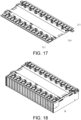
- the housing of the existing square-housing battery cell 110 are mostly made of metal material, in order to further enhance the insulation effect, please refer to FIG. 16 to FIG. 18 .
- the housing of the battery cell 110 of the battery cell array 100 is coated with an insulation film.
- the insulation film may be coated on the outer side of the entire battery cell array 100, or may be coated on each battery cell 110 in the battery cell array 100.
- the insulation film is coated on the external housing of each battery cell 110, a through window 111 is opened on the insulation film of the battery cell 110 on the outer side of the battery cell array 100.
- the through window 111 specifically penetrates toward the top cover 112 of the battery cell 110, and the housing surface of the battery cell 110 in the window 111 is bonded to the insulation layer 202.
- the bonding strength between the side plate 200 and the battery cell array 100 may be increased by directly bonding the housing surface of the battery cell 110 in the window 111 to the insulation layer 202 on the inner wall of the side plate 200.
- the insulation flange 311 protrudes correspondingly to a position above the window 111 to at least partially cover the position between the window 111 and the side plate 200.
- Such setting may ensure sufficient connection strength between the battery cell array 100 and the side plate 200 on the one hand, and on the other hand the creepage distance between the housing of the battery cell 110 at the window 11 and the side plate 200 may be increased through the insulation flange 311, thereby improving the electrical safety of the battery module.
- the battery cell array 100 includes a plurality of battery cells 110, and windows 111 are opened on the plurality of battery cells 110 on the same side surface of the battery cell array 100, and the insulation flange 311 extends along the arrangement direction of the battery cell 110 to at least partially block the electrical gap between a position above the window 111 on the same side and the side plate 200.
- This arrangement not only may increase the creepage distance between the housing of the battery cell 110 (such as an aluminum housing) and the exposed metal on the outer side of the side plate 200, but also may effectively ensure the safety performance of the product.
- the insulation flange 311 may be integrated onto the top plate 300 through hot pressing, or may be pasted on the top plate 300 through a cold-pasting insulation film, and the manufacturability is high.
- a whole strip of insulation flange 311 may be set above the battery cell array 100 on the same side of the top plate 300 to separate the windows 111 of all the battery cells 110 on the same side. There is no need to paste adhesive on each battery cell 110 to increase the creepage distance of the window 111; the assembly is relatively simple and the cost is low.
- the battery module also includes a cover plate 400, the battery module CCS is arranged on the top of the battery cell array 100, and the cover plate 400 insulates and seals the opening 201 to form insulation protection for the circuit board and the battery cell array 100. It should be noted that other parts of the battery module of the present disclosure that are not described in detail may be derived from the structure of the existing battery module and will not be repeated again.
- Vehicles may be fuel vehicles, gas vehicles or new energy vehicles, and new energy vehicles may be pure electric vehicles, hybrid vehicles or extended-range vehicles; spacecraft include airplanes, rockets, space shuttles and spacecraft, etc.; electric toys include fixed type or mobile electric toys, such as game consoles, electric car toys, electric boat toys and electric airplane toys, etc.; electric tools include metal cutting electric tools, grinding electric tools, assembly electric tools and railway electric tools, for example, electric drills, electric grinders, electric wrenches, electric screwdrivers, electric hammers, impact drills, concrete vibrators, electric planers, and more.
- the embodiments of the present disclosure do not impose special limitations on the above-mentioned electrical devices.
- an insulation flange 311 is disposed on the top plate 300, and the insulation flange 311 extends between the side plate 200 and the side wall of the battery cell array 100.
- the charge on the upper part of the battery cell array 100 needs to be turned down over the insulation flange 311 to reach the conductive part on the outer side of the side plate 200.
- the creepage distance between the housing of the battery cell 110 and the conductive parts on the outer side of the side plate 200 is increased, which increases the electrical safety performance of the battery module.
- a through window 111 is opened on the insulation film of the battery cell 110 on the outer side of the battery cell array 100, and the housing surface of the battery cell 110 inside the window 111 is bonded to the insulation layer 202.
- Such setting may ensure sufficient connection strength between the battery cell array 100 and the side plate 200 on the one hand, and on the other hand it is possible to increase the creepage distance between the housing of the battery cell 110 at the window 111 on the upper part and the side plate 200 through the insulation flange 311.
- windows 111 are provided on the plurality of battery cells 110 on the same side of the battery cell array 100, and the insulation flange 311 extends along the arrangement direction of the battery cell 110 to block the window 111 on the upper part and the side plate 200 on the same side.
Landscapes
- Chemical & Material Sciences (AREA)
- Chemical Kinetics & Catalysis (AREA)
- Electrochemistry (AREA)
- General Chemical & Material Sciences (AREA)
- Engineering & Computer Science (AREA)
- Manufacturing & Machinery (AREA)
- Battery Mounting, Suspending (AREA)
- Connection Of Batteries Or Terminals (AREA)
Applications Claiming Priority (2)
| Application Number | Priority Date | Filing Date | Title |
|---|---|---|---|
| CN202321282478.9U CN219717135U (zh) | 2023-05-24 | 2023-05-24 | 一种电池模组和包含该电池模组的用电装置 |
| CN202321281093.0U CN219937271U (zh) | 2023-05-24 | 2023-05-24 | 一种电池模组和包含该电池模组的用电装置 |
Publications (2)
| Publication Number | Publication Date |
|---|---|
| EP4468460A1 true EP4468460A1 (de) | 2024-11-27 |
| EP4468460B1 EP4468460B1 (de) | 2025-12-03 |
Family
ID=89121880
Family Applications (1)
| Application Number | Title | Priority Date | Filing Date |
|---|---|---|---|
| EP23214505.2A Active EP4468460B1 (de) | 2023-05-24 | 2023-12-06 | Batteriemodul und elektrische vorrichtung damit |
Country Status (4)
| Country | Link |
|---|---|
| US (1) | US20240396188A1 (de) |
| EP (1) | EP4468460B1 (de) |
| JP (1) | JP7745617B2 (de) |
| ES (1) | ES3056550T3 (de) |
Citations (3)
| Publication number | Priority date | Publication date | Assignee | Title |
|---|---|---|---|---|
| US20120003508A1 (en) * | 2010-07-02 | 2012-01-05 | Saft | Battery of electrochemical generators comprising a foam as inter-generator filler material |
| EP3282515A1 (de) * | 2015-09-25 | 2018-02-14 | LG Chem, Ltd. | Batteriemodul, batteriepack mit dem batteriemodul und fahrzeug mit dem batteriepack |
| US20210408621A1 (en) * | 2020-04-20 | 2021-12-30 | Sk Innovation Co., Ltd. | Battery Module |
Family Cites Families (4)
| Publication number | Priority date | Publication date | Assignee | Title |
|---|---|---|---|---|
| JP7366523B2 (ja) * | 2018-03-23 | 2023-10-23 | 株式会社Gsユアサ | 蓄電装置 |
| US12500286B2 (en) * | 2019-02-12 | 2025-12-16 | Sanyo Electric Co., Ltd. | Battery module comprising side separator with a biasing portion |
| WO2023013466A1 (ja) * | 2021-08-02 | 2023-02-09 | 株式会社Gsユアサ | 蓄電装置 |
| JP2023046882A (ja) * | 2021-09-24 | 2023-04-05 | トヨタ自動車株式会社 | 蓄電装置 |
-
2023
- 2023-11-29 US US18/522,237 patent/US20240396188A1/en active Pending
- 2023-12-01 JP JP2023203981A patent/JP7745617B2/ja active Active
- 2023-12-06 ES ES23214505T patent/ES3056550T3/es active Active
- 2023-12-06 EP EP23214505.2A patent/EP4468460B1/de active Active
Patent Citations (3)
| Publication number | Priority date | Publication date | Assignee | Title |
|---|---|---|---|---|
| US20120003508A1 (en) * | 2010-07-02 | 2012-01-05 | Saft | Battery of electrochemical generators comprising a foam as inter-generator filler material |
| EP3282515A1 (de) * | 2015-09-25 | 2018-02-14 | LG Chem, Ltd. | Batteriemodul, batteriepack mit dem batteriemodul und fahrzeug mit dem batteriepack |
| US20210408621A1 (en) * | 2020-04-20 | 2021-12-30 | Sk Innovation Co., Ltd. | Battery Module |
Also Published As
| Publication number | Publication date |
|---|---|
| JP2024169279A (ja) | 2024-12-05 |
| EP4468460B1 (de) | 2025-12-03 |
| JP7745617B2 (ja) | 2025-09-29 |
| ES3056550T3 (en) | 2026-02-23 |
| US20240396188A1 (en) | 2024-11-28 |
Similar Documents
| Publication | Publication Date | Title |
|---|---|---|
| CN215896628U (zh) | 一种电池单体、电池及用电装置 | |
| CN215989141U (zh) | 电池单体、电池以及用电装置 | |
| CN115693049B (zh) | 电池单体、电池和用电装置 | |
| JP7090725B2 (ja) | バッテリーセル、これを含むバッテリーモジュール、バッテリーラック及び電力貯蔵装置 | |
| US20240322375A1 (en) | Battery cell, method and apparatus for manufacturing same, battery, and power consuming device | |
| CN116457974A (zh) | 电池单体、电池、用电设备及电池单体的制造方法和设备 | |
| CN117223159A (zh) | 电池单体的壳体、电池单体、电池以及用电装置 | |
| CN117480647A (zh) | 电极组件、电池单体、电池以及用电装置 | |
| CN217768702U (zh) | 电池单体、电池以及用电装置 | |
| WO2023151413A1 (zh) | 用电设备、电池、电池单体及其制造方法 | |
| WO2022088493A1 (zh) | 等电位装置、等电位结构、电池及用电设备 | |
| US20250309476A1 (en) | Battery cell, battery, and power consuming device | |
| CN216389548U (zh) | 电池单体、电池以及用电装置 | |
| EP4468460A1 (de) | Batteriemodul und elektrische vorrichtung damit | |
| CN118077094A (zh) | 电池单体、电池以及用电装置 | |
| WO2026040267A1 (zh) | 电池单体、电池装置、用电装置及储能装置 | |
| CN219246815U (zh) | 电池和用电装置 | |
| CN219626756U (zh) | 外壳、电池单体、电池及用电装置 | |
| CN216120487U (zh) | 电池单体、电池及用电装置 | |
| CN116031500A (zh) | 电极组件、电池单体、电池、用电装置、制造方法和设备 | |
| KR101596266B1 (ko) | 다면체 전지셀 및 이를 포함하는 전지모듈 어셈블리 | |
| CN219937271U (zh) | 一种电池模组和包含该电池模组的用电装置 | |
| CN116762184A (zh) | 电极组件及其制作方法、电池单体、电池和用电装置 | |
| CN220253380U (zh) | 电池单体、电池及用电装置 | |
| CN219717135U (zh) | 一种电池模组和包含该电池模组的用电装置 |
Legal Events
| Date | Code | Title | Description |
|---|---|---|---|
| PUAI | Public reference made under article 153(3) epc to a published international application that has entered the european phase |
Free format text: ORIGINAL CODE: 0009012 |
|
| STAA | Information on the status of an ep patent application or granted ep patent |
Free format text: STATUS: REQUEST FOR EXAMINATION WAS MADE |
|
| 17P | Request for examination filed |
Effective date: 20231206 |
|
| AK | Designated contracting states |
Kind code of ref document: A1 Designated state(s): AL AT BE BG CH CY CZ DE DK EE ES FI FR GB GR HR HU IE IS IT LI LT LU LV MC ME MK MT NL NO PL PT RO RS SE SI SK SM TR |
|
| GRAP | Despatch of communication of intention to grant a patent |
Free format text: ORIGINAL CODE: EPIDOSNIGR1 |
|
| STAA | Information on the status of an ep patent application or granted ep patent |
Free format text: STATUS: GRANT OF PATENT IS INTENDED |
|
| INTG | Intention to grant announced |
Effective date: 20250922 |
|
| GRAS | Grant fee paid |
Free format text: ORIGINAL CODE: EPIDOSNIGR3 |
|
| GRAA | (expected) grant |
Free format text: ORIGINAL CODE: 0009210 |
|
| STAA | Information on the status of an ep patent application or granted ep patent |
Free format text: STATUS: THE PATENT HAS BEEN GRANTED |
|
| P01 | Opt-out of the competence of the unified patent court (upc) registered |
Free format text: CASE NUMBER: UPC_APP_8979_4468460/2025 Effective date: 20251006 |
|
| AK | Designated contracting states |
Kind code of ref document: B1 Designated state(s): AL AT BE BG CH CY CZ DE DK EE ES FI FR GB GR HR HU IE IS IT LI LT LU LV MC ME MK MT NL NO PL PT RO RS SE SI SK SM TR |
|
| REG | Reference to a national code |
Ref country code: CH Ref legal event code: F10 Free format text: ST27 STATUS EVENT CODE: U-0-0-F10-F00 (AS PROVIDED BY THE NATIONAL OFFICE) Effective date: 20251203 Ref country code: GB Ref legal event code: FG4D |
|
| REG | Reference to a national code |
Ref country code: DE Ref legal event code: R096 Ref document number: 602023009269 Country of ref document: DE |
|
| REG | Reference to a national code |
Ref country code: IE Ref legal event code: FG4D |
|
| PGFP | Annual fee paid to national office [announced via postgrant information from national office to epo] |
Ref country code: AT Payment date: 20260113 Year of fee payment: 3 |
|
| PGFP | Annual fee paid to national office [announced via postgrant information from national office to epo] |
Ref country code: FR Payment date: 20251217 Year of fee payment: 3 |
|
| REG | Reference to a national code |
Ref country code: ES Ref legal event code: FG2A Ref document number: 3056550 Country of ref document: ES Kind code of ref document: T3 Effective date: 20260223 |
|
| REG | Reference to a national code |
Ref country code: NL Ref legal event code: MP Effective date: 20251203 |
|
| PGFP | Annual fee paid to national office [announced via postgrant information from national office to epo] |
Ref country code: ES Payment date: 20260105 Year of fee payment: 3 |
|
| REG | Reference to a national code |
Ref country code: LT Ref legal event code: MG9D |
|
| PG25 | Lapsed in a contracting state [announced via postgrant information from national office to epo] |
Ref country code: NO Free format text: LAPSE BECAUSE OF FAILURE TO SUBMIT A TRANSLATION OF THE DESCRIPTION OR TO PAY THE FEE WITHIN THE PRESCRIBED TIME-LIMIT Effective date: 20260303 |
|
| PGFP | Annual fee paid to national office [announced via postgrant information from national office to epo] |
Ref country code: DE Payment date: 20251217 Year of fee payment: 3 |
|
| PG25 | Lapsed in a contracting state [announced via postgrant information from national office to epo] |
Ref country code: HR Free format text: LAPSE BECAUSE OF FAILURE TO SUBMIT A TRANSLATION OF THE DESCRIPTION OR TO PAY THE FEE WITHIN THE PRESCRIBED TIME-LIMIT Effective date: 20251203 Ref country code: FI Free format text: LAPSE BECAUSE OF FAILURE TO SUBMIT A TRANSLATION OF THE DESCRIPTION OR TO PAY THE FEE WITHIN THE PRESCRIBED TIME-LIMIT Effective date: 20251203 |
|
| PG25 | Lapsed in a contracting state [announced via postgrant information from national office to epo] |
Ref country code: RS Free format text: LAPSE BECAUSE OF FAILURE TO SUBMIT A TRANSLATION OF THE DESCRIPTION OR TO PAY THE FEE WITHIN THE PRESCRIBED TIME-LIMIT Effective date: 20260303 |