EP4468490A1 - Bloc-batterie et véhicule le comprenant - Google Patents
Bloc-batterie et véhicule le comprenant Download PDFInfo
- Publication number
- EP4468490A1 EP4468490A1 EP23807814.1A EP23807814A EP4468490A1 EP 4468490 A1 EP4468490 A1 EP 4468490A1 EP 23807814 A EP23807814 A EP 23807814A EP 4468490 A1 EP4468490 A1 EP 4468490A1
- Authority
- EP
- European Patent Office
- Prior art keywords
- opening
- closing member
- battery
- battery pack
- flame
- Prior art date
- Legal status (The legal status is an assumption and is not a legal conclusion. Google has not performed a legal analysis and makes no representation as to the accuracy of the status listed.)
- Granted
Links
Images








Classifications
-
- H—ELECTRICITY
- H01—ELECTRIC ELEMENTS
- H01M—PROCESSES OR MEANS, e.g. BATTERIES, FOR THE DIRECT CONVERSION OF CHEMICAL ENERGY INTO ELECTRICAL ENERGY
- H01M50/00—Constructional details or processes of manufacture of the non-active parts of electrochemical cells other than fuel cells, e.g. hybrid cells
- H01M50/30—Arrangements for facilitating escape of gases
- H01M50/317—Re-sealable arrangements
- H01M50/325—Re-sealable arrangements comprising deformable valve members, e.g. elastic or flexible valve members
- H01M50/333—Spring-loaded vent valves
-
- H—ELECTRICITY
- H01—ELECTRIC ELEMENTS
- H01M—PROCESSES OR MEANS, e.g. BATTERIES, FOR THE DIRECT CONVERSION OF CHEMICAL ENERGY INTO ELECTRICAL ENERGY
- H01M50/00—Constructional details or processes of manufacture of the non-active parts of electrochemical cells other than fuel cells, e.g. hybrid cells
- H01M50/30—Arrangements for facilitating escape of gases
- H01M50/308—Detachable arrangements, e.g. detachable vent plugs or plug systems
-
- H—ELECTRICITY
- H01—ELECTRIC ELEMENTS
- H01M—PROCESSES OR MEANS, e.g. BATTERIES, FOR THE DIRECT CONVERSION OF CHEMICAL ENERGY INTO ELECTRICAL ENERGY
- H01M50/00—Constructional details or processes of manufacture of the non-active parts of electrochemical cells other than fuel cells, e.g. hybrid cells
- H01M50/30—Arrangements for facilitating escape of gases
- H01M50/35—Gas exhaust passages comprising elongated, tortuous or labyrinth-shaped exhaust passages
- H01M50/367—Internal gas exhaust passages forming part of the battery cover or case; Double cover vent systems
-
- B—PERFORMING OPERATIONS; TRANSPORTING
- B60—VEHICLES IN GENERAL
- B60L—PROPULSION OF ELECTRICALLY-PROPELLED VEHICLES; SUPPLYING ELECTRIC POWER FOR AUXILIARY EQUIPMENT OF ELECTRICALLY-PROPELLED VEHICLES; ELECTRODYNAMIC BRAKE SYSTEMS FOR VEHICLES IN GENERAL; MAGNETIC SUSPENSION OR LEVITATION FOR VEHICLES; MONITORING OPERATING VARIABLES OF ELECTRICALLY-PROPELLED VEHICLES; ELECTRIC SAFETY DEVICES FOR ELECTRICALLY-PROPELLED VEHICLES
- B60L50/00—Electric propulsion with power supplied within the vehicle
- B60L50/50—Electric propulsion with power supplied within the vehicle using propulsion power supplied by batteries or fuel cells
- B60L50/60—Electric propulsion with power supplied within the vehicle using propulsion power supplied by batteries or fuel cells using power supplied by batteries
- B60L50/64—Constructional details of batteries specially adapted for electric vehicles
-
- H—ELECTRICITY
- H01—ELECTRIC ELEMENTS
- H01M—PROCESSES OR MEANS, e.g. BATTERIES, FOR THE DIRECT CONVERSION OF CHEMICAL ENERGY INTO ELECTRICAL ENERGY
- H01M50/00—Constructional details or processes of manufacture of the non-active parts of electrochemical cells other than fuel cells, e.g. hybrid cells
- H01M50/20—Mountings; Secondary casings or frames; Racks, modules or packs; Suspension devices; Shock absorbers; Transport or carrying devices; Holders
- H01M50/204—Racks, modules or packs for multiple batteries or multiple cells
-
- H—ELECTRICITY
- H01—ELECTRIC ELEMENTS
- H01M—PROCESSES OR MEANS, e.g. BATTERIES, FOR THE DIRECT CONVERSION OF CHEMICAL ENERGY INTO ELECTRICAL ENERGY
- H01M50/00—Constructional details or processes of manufacture of the non-active parts of electrochemical cells other than fuel cells, e.g. hybrid cells
- H01M50/20—Mountings; Secondary casings or frames; Racks, modules or packs; Suspension devices; Shock absorbers; Transport or carrying devices; Holders
- H01M50/204—Racks, modules or packs for multiple batteries or multiple cells
- H01M50/207—Racks, modules or packs for multiple batteries or multiple cells characterised by their shape
- H01M50/211—Racks, modules or packs for multiple batteries or multiple cells characterised by their shape adapted for pouch cells
-
- H—ELECTRICITY
- H01—ELECTRIC ELEMENTS
- H01M—PROCESSES OR MEANS, e.g. BATTERIES, FOR THE DIRECT CONVERSION OF CHEMICAL ENERGY INTO ELECTRICAL ENERGY
- H01M50/00—Constructional details or processes of manufacture of the non-active parts of electrochemical cells other than fuel cells, e.g. hybrid cells
- H01M50/20—Mountings; Secondary casings or frames; Racks, modules or packs; Suspension devices; Shock absorbers; Transport or carrying devices; Holders
- H01M50/233—Mountings; Secondary casings or frames; Racks, modules or packs; Suspension devices; Shock absorbers; Transport or carrying devices; Holders characterised by physical properties of casings or racks, e.g. dimensions
- H01M50/24—Mountings; Secondary casings or frames; Racks, modules or packs; Suspension devices; Shock absorbers; Transport or carrying devices; Holders characterised by physical properties of casings or racks, e.g. dimensions adapted for protecting batteries from their environment, e.g. from corrosion
-
- H—ELECTRICITY
- H01—ELECTRIC ELEMENTS
- H01M—PROCESSES OR MEANS, e.g. BATTERIES, FOR THE DIRECT CONVERSION OF CHEMICAL ENERGY INTO ELECTRICAL ENERGY
- H01M50/00—Constructional details or processes of manufacture of the non-active parts of electrochemical cells other than fuel cells, e.g. hybrid cells
- H01M50/20—Mountings; Secondary casings or frames; Racks, modules or packs; Suspension devices; Shock absorbers; Transport or carrying devices; Holders
- H01M50/289—Mountings; Secondary casings or frames; Racks, modules or packs; Suspension devices; Shock absorbers; Transport or carrying devices; Holders characterised by spacing elements or positioning means within frames, racks or packs
-
- H—ELECTRICITY
- H01—ELECTRIC ELEMENTS
- H01M—PROCESSES OR MEANS, e.g. BATTERIES, FOR THE DIRECT CONVERSION OF CHEMICAL ENERGY INTO ELECTRICAL ENERGY
- H01M50/00—Constructional details or processes of manufacture of the non-active parts of electrochemical cells other than fuel cells, e.g. hybrid cells
- H01M50/30—Arrangements for facilitating escape of gases
- H01M50/317—Re-sealable arrangements
-
- H—ELECTRICITY
- H01—ELECTRIC ELEMENTS
- H01M—PROCESSES OR MEANS, e.g. BATTERIES, FOR THE DIRECT CONVERSION OF CHEMICAL ENERGY INTO ELECTRICAL ENERGY
- H01M50/00—Constructional details or processes of manufacture of the non-active parts of electrochemical cells other than fuel cells, e.g. hybrid cells
- H01M50/30—Arrangements for facilitating escape of gases
- H01M50/35—Gas exhaust passages comprising elongated, tortuous or labyrinth-shaped exhaust passages
- H01M50/358—External gas exhaust passages located on the battery cover or case
-
- H—ELECTRICITY
- H01—ELECTRIC ELEMENTS
- H01M—PROCESSES OR MEANS, e.g. BATTERIES, FOR THE DIRECT CONVERSION OF CHEMICAL ENERGY INTO ELECTRICAL ENERGY
- H01M50/00—Constructional details or processes of manufacture of the non-active parts of electrochemical cells other than fuel cells, e.g. hybrid cells
- H01M50/30—Arrangements for facilitating escape of gases
- H01M50/383—Flame arresting or ignition-preventing means
-
- H—ELECTRICITY
- H01—ELECTRIC ELEMENTS
- H01M—PROCESSES OR MEANS, e.g. BATTERIES, FOR THE DIRECT CONVERSION OF CHEMICAL ENERGY INTO ELECTRICAL ENERGY
- H01M50/00—Constructional details or processes of manufacture of the non-active parts of electrochemical cells other than fuel cells, e.g. hybrid cells
- H01M50/30—Arrangements for facilitating escape of gases
- H01M50/394—Gas-pervious parts or elements
-
- H—ELECTRICITY
- H01—ELECTRIC ELEMENTS
- H01M—PROCESSES OR MEANS, e.g. BATTERIES, FOR THE DIRECT CONVERSION OF CHEMICAL ENERGY INTO ELECTRICAL ENERGY
- H01M2220/00—Batteries for particular applications
- H01M2220/20—Batteries in motive systems, e.g. vehicle, ship, plane
-
- H—ELECTRICITY
- H01—ELECTRIC ELEMENTS
- H01M—PROCESSES OR MEANS, e.g. BATTERIES, FOR THE DIRECT CONVERSION OF CHEMICAL ENERGY INTO ELECTRICAL ENERGY
- H01M50/00—Constructional details or processes of manufacture of the non-active parts of electrochemical cells other than fuel cells, e.g. hybrid cells
- H01M50/20—Mountings; Secondary casings or frames; Racks, modules or packs; Suspension devices; Shock absorbers; Transport or carrying devices; Holders
- H01M50/249—Mountings; Secondary casings or frames; Racks, modules or packs; Suspension devices; Shock absorbers; Transport or carrying devices; Holders specially adapted for aircraft or vehicles, e.g. cars or trains
-
- Y—GENERAL TAGGING OF NEW TECHNOLOGICAL DEVELOPMENTS; GENERAL TAGGING OF CROSS-SECTIONAL TECHNOLOGIES SPANNING OVER SEVERAL SECTIONS OF THE IPC; TECHNICAL SUBJECTS COVERED BY FORMER USPC CROSS-REFERENCE ART COLLECTIONS [XRACs] AND DIGESTS
- Y02—TECHNOLOGIES OR APPLICATIONS FOR MITIGATION OR ADAPTATION AGAINST CLIMATE CHANGE
- Y02E—REDUCTION OF GREENHOUSE GAS [GHG] EMISSIONS, RELATED TO ENERGY GENERATION, TRANSMISSION OR DISTRIBUTION
- Y02E60/00—Enabling technologies; Technologies with a potential or indirect contribution to GHG emissions mitigation
- Y02E60/10—Energy storage using batteries
Definitions
- the present disclosure relates to a battery pack and a vehicle including the same, and more particularly, to a battery pack configured to ensure structural stability in case of a thermal event and a vehicle including the same.
- lithium secondary batteries have little or no memory effect, and thus they are gaining more attention than nickel-based secondary batteries for their advantages that recharging can be done whenever it is convenient, the self-discharge rate is very low and the energy density is high.
- Lithium secondary batteries primarily comprise lithium-based oxides and carbon materials for a positive electrode active material and a negative electrode active material, respectively. Additionally, lithium secondary batteries comprise an electrode assembly including a positive electrode plate and a negative electrode plate coated with the positive electrode active material and the negative electrode active material, respectively, with a separator interposed between the positive electrode plate and the negative electrode plate and an outer packaging or a battery case accommodating the electrode assembly together with an electrolyte solution.
- lithium secondary batteries may be classified into can-type secondary batteries in which the electrode case is included in a metal can and pouch-type secondary batteries in which the electrode assembly is included in a pouch of an aluminum laminate sheet according to the shape of the battery case. Additionally, the can-type secondary batteries may be sub-classified into cylindrical batteries and prismatic batteries according to the shape of the metal can.
- the pouch of the pouch-type secondary batteries may largely include a lower sheet and an upper sheet disposed on the lower sheet.
- the electrode assembly including the positive electrode, the negative electrode and the separator stacked and wound is received in the pouch.
- the upper sheet and the lower sheet are sealed along the edges by heat welding.
- an electrode tab extended from each electrode may be coupled to an electrode lead, and an insulating film may be attached to an area of contact between the electrode lead and the sealing portion.
- the pouch-type secondary batteries may have flexibility to form various shapes. Additionally, the pouch-type secondary batteries may realize secondary batteries of the same capacity with smaller volume and mass.
- the secondary batteries are used to manufacture a battery module or a battery pack by stacking or piling up a plurality of battery cells with or without mounting in a cartridge to form a closely packed structure, and electrically connecting them.
- the battery pack requires configuration for properly controlling the thermal event.
- the present disclosure is designed to solve the above-described problem, and therefore the present disclosure is directed to providing a battery pack configured to ensure structural stability in case of a thermal event and a vehicle including the same.
- a battery pack includes a battery module, and a pack housing accommodating the battery module in a module receiving portion, and including an opening/closing member configured to vent a venting gas or flame out of the module receiving portion in an event of thermal runaway in the battery module.
- the pack housing includes a side frame which forms a side of the pack housing, and at least a portion of which is disposed facing the opening/closing member, a flow path disposed between the module receiving portion and the side frame, and formed in communication with the module receiving portion through a circulation hole formed by opening up of the opening/closing member in the event of thermal runaway in the battery module, and an exit port disposed in the side frame, communicating with the flow path and configured to vent the venting gas or flame out of the pack housing.
- the opening/closing member may be configured such that an end contacts the side frame in the event of thermal runaway in the battery module.
- the opening/closing member may be configured to be open at an acute angle with respect to the circulation hole in the event of thermal runaway in the battery module.
- the exit port may be formed at a location in the side frame after the venting gas or flame flowing in the flow path bends on or more times.
- a plurality of the battery modules may be provided, and a plurality of the module receiving portions may be provided, the battery module may be received in each of the plurality of module receiving portions, and each of the plurality of module receiving portions may be configured to be air-tightly closed by a partition.
- each opening/closing member corresponding to each module receiving portion may be disposed in the partition.
- each opening/closing member may be configured to be open at an acute angle with respect to the circulation hole in the event of thermal runaway in the plurality of battery modules, and at least some of the opening/closing members may be configured to reduce an opening angle toward the exit port.
- the opening/closing member located furthest away from the exit port may be configured such that an end contacts the side frame in the event of thermal runaway in the plurality of battery modules.
- At least some of the opening/closing members may be configured to reduce a length toward the exit port.
- an interrupt member configured to prevent the flame may be disposed on a surface of each opening/closing member facing outside of the module receiving portion.
- the battery pack may further include a guide member disposed in a portion of the flow path located at a corner of the side frame, and configured to guide the venting gas or flame towards the exit port.
- a guide member disposed in a portion of the flow path located at a corner of the side frame, and configured to guide the venting gas or flame towards the exit port.
- the battery pack may further include a mesh member disposed in the exit port, and configured to filter out the flame and allow the venting gas to pass through.
- a vehicle according to another aspect of the present disclosure includes at least one battery pack according to an aspect of the present disclosure as described above.
- venting gas and/or flame may be possible to prevent venting gas and/or flame from staying in the pack housing, and guide the venting of venting gas and/or flame out of the pack housing more effectively.
- the present disclosure includes many different embodiments. In the description of substantially identical or similar components for each embodiment, redundant description is omitted and difference(s) is described.
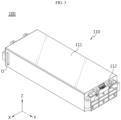
- FIG. 1 is a diagram showing a battery pack 10 according to an embodiment of the present disclosure
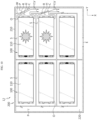
- FIG. 2 is a diagram illustrating the detailed structure of the battery pack 10 of FIG. 1
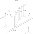
- FIG. 3 is a diagram showing a battery module 100 of the battery pack 10 of FIG. 2
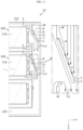
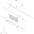
- FIG. 4 is an enlarged diagram of section A in FIG. 2
- FIG. 5 is a diagram showing an opening/closing member C in open state in FIG. 4 .
- illustration of a top cover 230 as described below is omitted.
- the X axis direction shown in the diagrams may refer to a front-rear direction
- the Y axis direction may refer to a left-right direction perpendicular to the X axis direction on the horizontal plane (XY plane)
- the Z axis direction may refer to an up-down direction perpendicular to the X axis direction and Y axis direction.
- the battery pack 10 may include a battery module 100 and a pack housing 200.
- the battery module 100 may include a cell assembly (not shown) and a module case 110.
- the cell assembly may include at least one battery cell.
- the battery cell may refer to a secondary battery.
- the battery cell may include a pouch type battery cell, a cylindrical battery cell or a prismatic battery cell.
- the battery cell may be a pouch type battery cell.
- the module case 110 may accommodate the cell assembly. To this end, the module case 110 may have an internal receiving space for receiving the cell assembly inside.
- the module case 110 may include a case body 111 accommodating the cell assembly and having open ends at two sides and an end plate 112 coupled to the two sides of the case body 111.
- the case body 111 may be formed in the shape of a pipe having two open ends, and the end plates 112 may be coupled to the two open ends of the case body 111. Referring to FIG. 3 , the end plates 112 may face each other along the Y axis. The end plates 112 may be coupled to the open ends of the case body 111 to prevent the exposure of electrode leads of the battery cells and a portion of connected part between the electrode leads and busbars.
- the pack housing 200 may be configured to receive the battery module 100.
- the pack housing 200 may have a module receiving portion S.
- the module receiving portion S may be an empty space shaped to receive the battery module 100 therein.
- the module receiving portion S may be shaped to receive the battery module 100 therein through a partition W as described below.
- the pack housing 200 may comprise a material having heat resistance and high strength.
- an event such as thermal runaway may occur in the specific battery module 100.
- high temperature and high pressure venting gas may be produced in the specific battery module 100, and when the venting gas meets oxygen, flame may occur inside or outside of the battery module 100.
- the venting gas or flame may be highly likely to spread to the other battery module 100 adjacent to the specific battery module 100, and as a consequence, simultaneous thermal runaway or fires may occur in the plurality of battery modules 100.
- the conventional battery pack includes the plurality of battery modules in the airtight pack housing and does not have a proper vent path that directs venting gas or flame out, and thus is vulnerable to multiple simultaneous fires.
- the pack housing 200 of the present disclosure may include the opening/closing member C.
- the opening/closing member C may be configured to vent the venting gas and/or flame out of the module receiving portion S in the event of thermal runaway in the battery module 100.
- the opening/closing member C may be configured to open or close the inside of the module receiving portion S according to the pressure in the module receiving portion S caused by venting gas in the event of thermal runaway of the battery module 100.
- the opening/closing member C may be rotatably coupled to one side of the module receiving portion S.
- the opening/closing member C may be rotatably coupled to one side of the module receiving portion S through a coupling member I.
- the coupling member I may be a hinge, but is not limited thereto.
- the coupling member I may include elastics and may be configured to control a rotational motion of the opening/closing member C.
- the elastics may be a hinge spring.
- the opening/closing member C may be kept closed by the elastic force of the elastics of the coupling member I when thermal runaway does not occur in the battery module 100.
- the opening/closing member C may be configured to deploy in the outward direction of the module receiving portion S to vent the venting gas and/or flame out of the module receiving portion S.
- the pressure in the module receiving portion S equal to or higher than the reference pressure may represent that the pressure in the module receiving portion S is higher than the external pressure of the module receiving portion S due to the produced venting gas.
- the compression force of air in the module receiving portion S applied to the opening/closing member C by the venting gas may be greater than the elastic force of the coupling member I that keeps the opening/closing member C closed. Accordingly, in the event of thermal runaway in the battery module 100, the opening/closing member C may easily deploy in the outward direction of the module receiving portion S by a pressure difference between the outside and inside of the module receiving portion S.
- venting gas and/or flame may be rapidly vented through the open portion of the module receiving portion S. Additionally, when venting gas is vented, the internal pressure of the battery module 100 may drop fast.
- the opening/closing member C may be configured to close the module receiving portion S when the pressure in the module receiving portion S drops down to the reference pressure as venting gas is vented.
- the pressure in the module receiving portion S equal to or lower than the reference pressure may represent that the pressure in the module receiving portion S is lower than the external pressure of the module receiving portion S as venting gas is vented. In this case, not only the compression force of the outside air of the module receiving portion S applied to the opening/closing member C but also the elastic force of the coupling member I that keeps the opening/closing member C closed may be applied.
- the opening/closing member C may smoothly operate in the inward direction of the module receiving portion S by a pressure difference between the outside and inside of the module receiving portion S to close the module receiving portion S.
- venting gas emission reduces, it may be possible to effectively prevent backflow of venting gas and/or flame into the module receiving portion S by making it easy to close the module receiving portion S by the opening/closing member C. Additionally, it may be possible to suppress an additional fire in the module receiving portion S by preventing oxygen from entering the module receiving portion S.
- the pack housing 200 may include a side frame 210, a flow path P and an exit port E.
- the side frame 210 may form a side of the pack housing 200, and at least a portion may be disposed facing the opening/closing member C.
- the opening/closing member C may be disposed facing all the sides of the side frame 210, and may be disposed facing some of the sides of the side frame 210.
- the flow path P may be disposed between the module receiving portion S and the side frame 210, and configured to communicate with the module receiving portion S through a circulation hole H formed by the opening up of the opening/closing member C in the event of thermal runaway in the battery module 100.
- the flow path P may provide a space for movement to allow venting gas and/or flame vented through the circulation hole H to exit the pack housing 200.
- the opening/closing member C may be open towards the side frame 210 that it is facing, in the event of thermal runaway in the battery module 100. Additionally, the opening/closing member C may be configured to open or close the circulation hole H according to the pressure in the module receiving portion S in the event of thermal runaway in the battery module 100.
- the exit port E may be disposed in the side frame 210, in communication with the flow path P and configured to allow venting gas and/or flame to exit the pack housing 200.
- the exit port E may be formed in the shape of a hole having a predetermined area.
- the opening/closing member C may be open such that the end faces towards the exit port E in the event of thermal runaway in the battery module 100.
- venting gas and/or flame vented from the module receiving portion S may be guided in the space between the module receiving portion S and the side of the pack housing 200 and exit the pack housing 200. Accordingly, it may be possible to allow venting gas and/or flame to exit the pack housing 200 more stably.
- the pack housing 200 may further include a floor frame 220 and the top cover 230.
- the floor frame 220 may form the bottom of the pack housing 200 and may be coupled to the side frame 210.
- the top cover 230 may be coupled to the top of the side frame 210, and may air-tightly close the top of the battery module 100. In particular, the top cover 230 may air-tightly close the top of the module receiving portion S.
- FIGS. 6 and 7 are diagrams showing an example of venting of venting gas or flame in the event of thermal runaway in the battery module 100. Specifically, FIGS. 6 and 7 show an example of thermal runaway in one battery module 100. In this instance, in FIGS. 6 and 7 , venting gas and flame may be indicated by the symbols 'V' and 'F', respectively.
- the opening/closing member C may be configured such that the end contacts the side frame 210 in the event of thermal runaway in the battery module 100.
- the length of the opening/closing member C (for example, the length extended from one side of the module receiving portion S) may be equal to or longer than the length (in Y axis direction) between the circulation hole H and the side frame 210.
- the opening/closing member C may prevent venting gas and/or flame from entering the area opposite the exist port E on the basis of the location of contact between the end of the opening/closing member C and the side frame 210 in the flow path P. Accordingly, it may be possible to prevent venting gas and/or flame from staying in the pack housing 200, and guide the venting of venting gas and/or flame out of the pack housing 200 more effectively.
- the opening/closing member C may be configured to be open at an acute angle with respect to the circulation hole H in the event of thermal runaway in the battery module 100.
- a restriction member R configured to restrict the opening angle of the opening/closing member C to less than a predetermined angle may be disposed on one side of the module receiving portion S.
- the restriction member R may have a plate shape.
- the restriction member R may be disposed at an acute angle with respect to the circulation hole H.
- the angle between the restriction member R and the circulation hole H may be set in an angle range between more than 0° and less than 90°.
- the restriction member R may be disposed on one side of the module receiving portion S such that it is further apart from the exit port E than the opening/closing member C. Meanwhile, the restriction member R may have a shorter length (for example, the length extended from one side of the module receiving portion S) than the opening/closing member C, but is not limited thereto. Meanwhile, the angle between the restriction member R and the circulation hole H may be set in a range in which the end of the opening/closing member C may contact the side frame 210 in the event of thermal runaway in the battery module 100.
- the opening/closing member C when the opening/closing member C is open towards the side frame 210 in the event of thermal runaway in the battery module 100, the opening/closing member C may come into contact with the restriction member R, thereby restricting the opening angle to less than the predetermined angle with respect to the circulation hole H.
- the opening/closing member C may be configured to be open at the acute angle with respect to the circulation hole H by the restriction member R.
- venting gas and/or flame vented from the module receiving portion S by thermal runaway in the battery module 100 may be vented to the flow path P along the inner surface of the opening/closing member C inclined with respect to the circulation hole H. Accordingly, it may be possible to guide the flow of venting gas and/or flame towards the exit port E more effectively.
- the exit port E may be formed at a location in the side frame 210 after venting gas and/or flame flowing in the flow path P bends one or more times.
- the exit port E may be formed at the location in the side frame 210 after the flow of venting gas and/or flame changes one or more times.
- the exit port E may be disposed at a location perpendicular to the location of the opening/closing member C in the flow path P on the basis of the corner of the side frame 210.
- venting gas and/or flame may be vented out of the pack housing 200 at the location after the flow of venting gas and/or flame flowing in the flow path P changes one or more times, thereby effectively preventing backflow of venting gas and/or flame into the portion of the flow path P in which the opening/closing member C is located.
- a plurality of battery modules 100 may be provided, and a plurality of module receiving portions S corresponding to the plurality of battery modules 100 may be provided.
- the plurality of module receiving portions S may be independent of each other.
- each of the plurality of battery modules 100 may be received in each of the plurality of module receiving portions S.
- each of the plurality of module receiving portions S may be configured to be air-tightly closed by the partition W.
- the partition W may include a material having heat resistance and high strength.
- the partition W may form a side of each module receiving portion S. Additionally, the partition W may be extended in the vertical direction corresponding to the height of the side frame 210. In this instance, the components of the partition W may be joined to each other by welding, and may be integrally formed by injection molding, but the manufacturing method is not limited thereto.
- the partition W may be spaced apart from the side frame 210.
- the flow path P may be formed at a gap between the partition W and the side frame 210.
- the floor frame 220 may be coupled to the bottom of the partition W, and the top cover 230 may be coupled to the top of the partition W. Meanwhile, in the battery pack 10 of the present disclosure, the top cover 230 may cover up the side frame 210 and the top of the partition W, and another cover (not shown) may be present on the top of the partition W.
- the partition W may have each opening/closing member C corresponding to each module receiving portion S.
- the opening/closing member C may be rotatably coupled to one side of the partition W.
- the opening/closing member C may be rotatably coupled to one side of the partition W through the coupling member I.
- the restriction member R may be disposed on one side of the partition W and configured to restrict the opening angle of the opening/closing member C to less than the predetermined angle.
- Each opening/closing member C disposed in the partition W, each corresponding to each module receiving portion S, may be configured to open or close the circulation hole H according to the pressure in each module receiving portion S in the event of thermal runaway in the battery module 100.
- the battery module 100 of the present disclosure may have a venting hole O in at least one surface of the module case 110 to vent the venting gas and/or flame.
- the venting hole O may be disposed in a top surface of the module case 110.
- the venting hole O may be disposed in two side surfaces of the module case 110.
- the two surfaces may be opposite surfaces along the X axis, and the venting hole O may be extended along the Z axis.
- the plurality of battery modules 100 may be received in each module receiving portion S such that the venting hole O is disposed close to the opening/closing member C.
- venting gas and/or flame generated in the battery module 100 may be directionally vented towards the two sides of the battery module 100 through the venting hole O. Additionally, venting gas and/or flame vented through the venting hole O may be rapidly vented to the flow path P through the circulation hole H via the space between the battery module 100 and the partition W in the module receiving portion S or the space between the battery module 100 and the side frame 210.
- venting gas and/or flame vented through the venting hole O in the two side surfaces of the battery module 100 may be guided towards the flow path P and vented out of the pack housing 200 more rapidly.
- FIGS. 8 and 9 are diagrams showing another example of venting of venting gas or flame in the event of thermal runaway in the battery module 100. Specifically, FIGS. 8 and 9 show an example of thermal runaway in the plurality of battery modules 100. In this instance, in FIGS. 8 and 9 , venting gas and flame may be indicated by the symbols 'V' and 'F', respectively.
- At least some of the opening/closing members C may be configured to be open towards the side frame 210 to a lesser extent toward the exit port E in the event of thermal runaway in the plurality of battery modules 100.
- each opening/closing member C may be configured to be open at an acute angle with respect to the circulation hole H in the event of thermal runaway in the plurality of battery modules 100.
- opening/closing members C may be configured to reduce the opening angle toward the exit port E.
- the restriction member R configured to restrict the opening angle of the opening/closing member C to less than the predetermined angle may be disposed on one side of the module receiving portion S for each opening/closing member C.
- the restriction member R may be disposed at an acute angle with respect to the circulation hole H.
- restriction members R may be configured to reduce the angle with respect to the circulation hole H toward the exit port E.
- opening/closing members C may be configured to reduce the opening angle toward the exit port E.
- each opening/closing member C may be configured to reduce the opening angle toward the exit port E.
- the restriction member R disposed for each opening/closing member C may be configured to reduce the angle with respect to the circulation hole H toward the exit port E.
- venting gas and/or flame vented to the flow path P through the opening up of the specific opening/closing member C may be allowed to smoothly flow toward the exit port E without being restricted by the outer surface of the other opening/closing member C located closer to the exit port E than the specific opening/closing member C.
- venting gas and/or flame may be vented to the flow path P along the inner surface of the opening/closing member C so as to be guided in a direction close to the side frame 210. Accordingly, it may be possible to minimize the likelihood that venting gas and/or flame vented to the flow path P through the opening up of the specific opening/closing member C may hit the outer surface of the other opening/closing member C located closer to the exit port E than the specific opening/closing member C.
- venting gas and/or flame vented to the flow path P through the opening up of the specific opening/closing member C hits the outer surface of the other opening/closing member C it may be possible to minimize the flow (backflow) of venting gas and/or flame vented to the flow path P back into the module receiving portion S.
- venting gas and/or flame vented from the inside of each module receiving portion S may be vented to the flow path P along the inner surface of the opening/closing member C inclined with respect to the circulation hole H. Accordingly, the flows of venting gas and/or flame may be stably guided towards the exit port E.
- the opening/closing member C located furthest away from the exit port E may be configured such that the end contacts the side frame 210 in the event of thermal runaway in the plurality of battery modules 100.
- the length (for example, the length extended from one side of the module receiving portion S) of the opening/closing member C located furthest away from the exit port E may be equal to or longer than the length (in Y axis direction) between the circulation hole H and the side frame 210.
- the angle between the circulation hole H and the restriction member R that restricts the opening angle of the opening/closing member C located furthest away from the exit port E may be set in the range in which the end of the opening/closing member C located furthest away from the exit port E may contact the side frame 210 in the event of thermal runaway in the battery module 100.
- the opening/closing member C located furthest away from the exit port E may prevent venting gas and/or flame from entering the area opposite the exit port E on the basis of the location of contact between the end of the corresponding opening/closing member C and the side frame 210 in the flow path P. Accordingly, when thermal runaway occurs in the plurality of battery modules 100, it may be possible to prevent venting gas and/or flame from staying in the pack housing 200 and guide the venting of the venting gas and/or flame out of the pack housing 200 more effectively.
- FIG. 10 is a diagram showing a battery pack 12 according to a second embodiment of the present disclosure.
- the battery pack 12 according to this embodiment is similar to the battery pack 10 of the previous embodiment, and in the description of the components that are substantially identical or similar to those of the previous embodiment, redundant description is omitted, and different(s) between this embodiment and the previous embodiment will be described below.
- venting gas and flame are indicated by the symbols 'V' and 'F', respectively.
- each opening/closing member C may be configured to be open at an acute angle with respect to the circulation hole H in the event of thermal runaway in the plurality of battery modules 100. This may be accomplished by the restriction member R.
- each circulation hole H may be sized to conform to the size of each opening/closing member C.
- each opening/closing member C may be configured to reduce the length toward the exit port E.
- venting gas and/or flame vented to the flow path P through the opening up of the specific opening/closing member C may be allowed to smoothly flow towards the exit port E without being restricted by the outer surface of the other opening/closing member C located closer to the exit port E than the specific opening/closing member C.
- venting gas and/or flame may be vented to the flow path P along the inner surface of the opening/closing member C so as to be guided in a direction close to the side frame 210. Accordingly, it may be possible to minimize the likelihood that venting gas and/or flame vented to the flow path P through the opening up of the specific opening/closing member C hits the outer surface of the other opening/closing member C located closer to the exit port E than the specific opening/closing member C.
- venting gas and/or flame vented to the flow path P through the opening up of the specific opening/closing member C hits the outer surface of the other opening/closing member C it may be possible to minimize the flow (backflow) of venting gas and/or flame vented to the flow path P back into the module receiving portion S.
- the battery pack 12 when simultaneously thermal runaway occurs in the plurality of battery modules 100, it may be possible to prevent restriction of the flows of venting gas and/or flame vented to the flow path P through the opening up of each opening/closing member C towards the exit port E, and effectively prevent backflow of venting gas and/or flame into the plurality of module receiving portions S.
- FIG. 11 is a diagram showing a battery pack 14 according to a third embodiment of the present disclosure.
- the battery pack 14 according to this embodiment is similar to the battery pack 10 of the previous embodiment, and in the description of the components that are substantially identical or similar to those of the previous embodiment, redundant description is omitted, and different(s) between this embodiment and the previous embodiment will be described below.
- venting gas and flame are indicated by the symbols 'V' and 'F', respectively.
- the battery pack 14 may further include an interrupt member T.
- the interrupt member T may be disposed on a surface (an outer surface) of each opening/closing member C facing the outside of the module receiving portion S.
- the interrupt member T may interrupt flame (or sparks) occurring in the event of thermal runaway in the battery module 100.
- a plurality of interrupt members T may be formed in the shape of protrusion on the outer surface of the opening/closing member C.
- FIG. 12 is a diagram showing a battery pack 16 according to a fourth embodiment of the present disclosure.
- the battery pack 16 according to this embodiment is similar to the battery pack 10 of the previous embodiment, and in the description of the components that are substantially identical or similar to those of the previous embodiment, redundant description is omitted, and different(s) between this embodiment and the previous embodiment will be described below.
- the battery pack 16 may further include a guide member G.
- the guide member G maybe disposed at a portion of the flow path P located at the corner of the side frame 210, and may be configured to guide venting gas and/or flame towards the exit port E.
- the guide member G may include a material having heat resistance and high strength.
- the guide member G may have one end coupled to the portion of the side frame 210 facing the opening/closing member C. Additionally, the guide member G may have the other end coupled to the portion of the side frame 210 in which the exit port E is located. Additionally, the guide member G may be inclined from the portion of the side frame 210 facing the opening/closing member C to the portion of the side frame 210 in which the exit port E is located.
- the flow of venting gas and/or flame flowing in the flow path P may be smoothly guided towards the exit port E. Additionally, since the flow of venting gas and/or flame changes through the guide member G inclined towards the exit port E, it may be possible to prevent backflow of venting gas and/or flame into the portion of the flow path P in which the opening/closing member C is located.
- FIG. 13 is a diagram showing a battery pack 18 according to a fifth embodiment of the present disclosure.
- the battery pack 18 according to this embodiment is similar to the battery pack 10 of the previous embodiment, and in the description of the components that are substantially identical or similar to those of the previous embodiment, redundant description is omitted, and different(s) between this embodiment and the previous embodiment will be described below.
- the battery pack 18 may further include a mesh member M.
- the mesh member M may be disposed in the exit port E and configured to filter out flame and allow venting gas to pass through.
- the mesh member M may be in the shape of a plate member having pores, or a mesh formed by weaving a plurality of wires. In this instance, the pores may have a sufficient size to filter out flame vented out of the pack housing 200 from the flow path P. That is, the mesh member M may prevent flame from being vented out of the pack housing 200 and causing a fire.
- the battery pack 18 it may be possible to suppress the passage of flame and allow venting gas to pass through the mesh structure formed in the exit port E. Accordingly, it may be possible to minimize the exposure of flame through the pack housing 200 and achieve rapid venting of venting gas.
- FIG. 14 is a diagram showing a battery pack 20 according to another embodiment of the present disclosure.
- each opening/closing member C may further include a bending portion B formed by bending a portion of the opening/closing member C.
- the bending portion B may bend from the center of the opening/closing member C in the outward direction of the module receiving portion S.
- the bending portion B may be at an obtuse angle to prevent restriction of the movement of venting gas and/or flame vented through the circulation hole H. Additionally, unlike FIG. 14 , the bending portion B may be curved.
- the angle formed by the bending portion B may be greater.
- the opening/closing member C located furthest away from the exit port E may be at 180° or an angle approximately close to 180° and may contact the side frame 210.
- the opening/closing member C' located close to the exit port E may be bent at a smaller angle, for example, 120°.
- the bending portion B' may minimize the likelihood that the flow of venting gas and/or flame F, V vented to the flow path P through the opening up of the opening/closing member C located further away from the exit port E than the specific opening/closing member C' towards the exit port E hits the outer surface of the specific opening/closing member C', thereby preventing obstruction of the other flow of gas or flame vented to the flow path P in the rear side.
- venting gas or flame F', V' when venting gas or flame F', V' is vented through the circulation hole H', venting gas or flame F', V' may be vented to the flow path P more smoothly through the bent shape of the opening/closing member C'. That is, by the above-described exemplary configuration, when the opening/closing member C' is open, the bent end may be approximately parallel to the flow direction of the flow path P. Accordingly, flame F', V' or the like vented to the corresponding opening/closing member C' may be smoothly vented and flow along the flow direction of the flow path P as indicated in FIG. 14 .
- FIG. 15 is a diagram showing a battery pack 22 according to another embodiment of the present disclosure.
- each opening/closing member C may further include a hinge portion G to rotate a portion of the opening/closing member C.
- the hinge portion G may be disposed in a predetermined portion of the opening/closing member C, especially, at the center. Additionally, the hinge portion G may be configured to form an obtuse angle between two sides to prevent restriction of the movement of venting gas and/or flame vented through the circulation hole H. Further, the opening/closing member C may be unfolded such that the angle between the two sides of the hinge portion G is up to 180°.
- the hinge portion G may be configured such that the angle between two sides is 180° when there is no external pressure applied. That is, the opening/closing member C may be formed in a plate shape, in other words, such that the angle of the hinge portion G is 180° in a state that there is no external force applied or a predetermined level or less of force is applied. To this end, the hinge portion G may include elastics such as a spring. In the above-described exemplary configuration, when thermal runaway does not occur in the battery module 100, the opening/closing member C is not rotated by the hinge portion G and may be maintained at 180° and kept closed.
- the specific opening/closing member C" for example, the opening/closing member located at the center in the front-rear direction (X axis direction) may open the module receiving portion S for which it takes responsibility when the internal pressure of the module receiving portion S rises.
- the opening/closing member C" may be bent by gas and/or flame F, V vented from the other module receiving portion S.
- the end of the opening/closing member C" may be rotated towards the circulation hole H" by the compression force of venting gas and/or flame F, V vented from the rear side (-X axis direction) to the flow path P.
- the opening/closing member C located further away from the exit port E than the specific opening/closing member C" may be provided by the rotation of the hinge portion G towards the circulation hole H.
- an angle at which the end portion rotates towards the circulation hole H may be higher.
- the hinge portion G is not rotated and may be kept at 180° and contact the side frame 210.
- the opening/closing member C" located closer to the exit port E may be configured such that the end rotates better towards the circulation hole H" to provide a space for flow of gas (F, V) vented in the rear side.
- the opening/closing member C" located close to the exit port E may include elastics having lower elastic modulus than the opening/closing member C located further away from the exit port E.
- FIGS. 16 and 17 are diagrams showing a battery pack 24 according to another embodiment of the present disclosure.
- FIG. 16 is an exploded perspective view of the battery pack 24, and
- FIG. 17 is a diagram showing the battery pack 24 with a top cover 232 coupled thereto when viewed from the top.
- the battery pack 24 may include the restriction member R incorporated into the top cover 230.
- the top cover 232 may include the restriction member R that protrudes from at least one surface of the top cover 232 to restrict the opening angle of the opening/closing member C to less than the predetermined angle.
- the top cover 232 may be in the shape of a rectangular plate coupled to the top of the partition W and configured to simultaneously cover the side frame 210 and the partition W.
- the partition W structure formed on top of the floor frame 220 is structurally simplified, which makes the fabrication process easy and reduces the cost. Additionally, when the top cover 232 is assembled with the floor frame 220, the restriction member R guides the assembly location, thereby enhancing the assembly efficiency, and one end of the restriction member R is supported on the partition W, so it may be possible to prevent the top cover 232 from moving in the horizontal direction (X axis or Y axis direction) and the vertical direction (Z axis direction), thereby enhancing the coupling strength between the top cover 232 and the floor frame 220.
- the height of the restriction member R of the top cover 232 may be equal to or smaller than the height of the partition W or the side frame 210.
- the top cover 230 when the height of the restriction member R is equal to the height of the partition W or the side frame 210, unlike the above-described embodiments in which the top cover 230 is coupled to the side frame 210 and the top end of the partition W, the top cover 230 may be directly coupled to not only the side frame 210 and the partition W but also the floor frame 220 by the restriction member R. That is, the restriction member R may be coupled to one side of the partition W to which the opening/closing member C is coupled and may be coupled with the lower end in contact with the floor frame 220.
- the battery pack 20 may prevent venting gas and/or flame from staying in the pack housing 200, and guide the venting of venting gas and/or flame out of the pack housing 200 more effectively, and ensure coupling stability of the battery pack 24 by the restriction member R of the top cover 232 coupled to the partition W and the floor frame 220.
- venting gas and/or flame may be possible to prevent venting gas and/or flame from staying in the pack housing 200 and guide the venting of venting gas and/or flame out of the pack housing 200 more effectively.
- the battery pack 10, 12, 14, 16, 18, 20, 22, 24 may further include devices for controlling the charge/discharge of the battery pack 10, 12, 14, 16, 18, 20, 22, 24, for example, a Battery Management System (BMS), a current sensor and a fuse.
- BMS Battery Management System
- the battery pack 10, 12, 14, 16, 18, 20, 22, 24 according to the present disclosure may be applied to a vehicle such as an electric vehicle. That is, the vehicle according to the present disclosure may include at least one battery pack 10, 12, 14, 16, 18, 20, 22, 24 according to the present disclosure.
Landscapes
- Chemical Kinetics & Catalysis (AREA)
- Electrochemistry (AREA)
- General Chemical & Material Sciences (AREA)
- Chemical & Material Sciences (AREA)
- Engineering & Computer Science (AREA)
- Sustainable Development (AREA)
- Life Sciences & Earth Sciences (AREA)
- Sustainable Energy (AREA)
- Power Engineering (AREA)
- Transportation (AREA)
- Mechanical Engineering (AREA)
- Aviation & Aerospace Engineering (AREA)
- Battery Mounting, Suspending (AREA)
- Gas Exhaust Devices For Batteries (AREA)
Applications Claiming Priority (2)
| Application Number | Priority Date | Filing Date | Title |
|---|---|---|---|
| KR20220059601 | 2022-05-16 | ||
| PCT/KR2023/005989 WO2023224291A1 (fr) | 2022-05-16 | 2023-05-02 | Bloc-batterie et véhicule le comprenant |
Publications (3)
| Publication Number | Publication Date |
|---|---|
| EP4468490A1 true EP4468490A1 (fr) | 2024-11-27 |
| EP4468490A4 EP4468490A4 (fr) | 2025-06-25 |
| EP4468490B1 EP4468490B1 (fr) | 2026-04-15 |
Family
ID=88835560
Family Applications (1)
| Application Number | Title | Priority Date | Filing Date |
|---|---|---|---|
| EP23807814.1A Active EP4468490B1 (fr) | 2022-05-16 | 2023-05-02 | Bloc-batterie et véhicule le comprenant |
Country Status (7)
| Country | Link |
|---|---|
| US (1) | US20240372208A1 (fr) |
| EP (1) | EP4468490B1 (fr) |
| JP (1) | JP2024533228A (fr) |
| KR (1) | KR20230160176A (fr) |
| CN (1) | CN117941148A (fr) |
| CA (1) | CA3245782A1 (fr) |
| WO (1) | WO2023224291A1 (fr) |
Cited By (1)
| Publication number | Priority date | Publication date | Assignee | Title |
|---|---|---|---|---|
| EP4579917A4 (fr) * | 2022-11-23 | 2025-12-31 | Lg Energy Solution Ltd | Bloc-batterie et dispositif le comprenant |
Families Citing this family (9)
| Publication number | Priority date | Publication date | Assignee | Title |
|---|---|---|---|---|
| DE102022107489B3 (de) * | 2022-03-30 | 2023-04-20 | Dr. Ing. H.C. F. Porsche Aktiengesellschaft | Kfz-Traktionsbatteriemodul |
| WO2025188043A1 (fr) * | 2024-03-07 | 2025-09-12 | 주식회사 엘지에너지솔루션 | Bloc-batterie |
| KR20250136045A (ko) * | 2024-03-07 | 2025-09-16 | 주식회사 엘지에너지솔루션 | 배터리 팩 |
| KR20250150800A (ko) * | 2024-04-12 | 2025-10-21 | 주식회사 엘지에너지솔루션 | 배터리 모듈, 이를 포함하는 배터리 팩 및 자동차 |
| KR20250155804A (ko) * | 2024-04-24 | 2025-10-31 | 주식회사 엘지에너지솔루션 | 전지 팩 및 이를 포함하는 디바이스 |
| JP2025166354A (ja) * | 2024-04-24 | 2025-11-06 | 株式会社Aescジャパン | 電池モジュール |
| KR20250173259A (ko) * | 2024-06-03 | 2025-12-10 | 주식회사 엘지에너지솔루션 | 배터리 모듈 |
| KR20250178591A (ko) * | 2024-06-19 | 2025-12-29 | 주식회사 엘지에너지솔루션 | 배터리 팩 및 이를 포함하는 자동차 |
| KR20260014139A (ko) * | 2024-07-23 | 2026-01-30 | 주식회사 엘지에너지솔루션 | 배터리 팩 및 이를 포함하는 자동차 |
Family Cites Families (11)
| Publication number | Priority date | Publication date | Assignee | Title |
|---|---|---|---|---|
| JP2015018706A (ja) * | 2013-07-11 | 2015-01-29 | 株式会社豊田自動織機 | 蓄電装置モジュール |
| WO2018023050A1 (fr) * | 2016-07-29 | 2018-02-01 | Crynamt Management Llc | Bloc-batterie haute densité |
| JP6821391B2 (ja) * | 2016-10-26 | 2021-01-27 | 三洋電機株式会社 | 電源装置及びこれを用いる車両並びに蓄電装置 |
| DE102016225057A1 (de) * | 2016-12-15 | 2018-06-21 | Bayerische Motoren Werke Aktiengesellschaft | Batterieeinheit für eine Traktionsbatterie und Traktionsbatterie |
| JP6920661B2 (ja) * | 2016-12-27 | 2021-08-18 | パナソニックIpマネジメント株式会社 | 電池モジュール |
| KR102664362B1 (ko) * | 2019-02-12 | 2024-05-07 | 한화에어로스페이스 주식회사 | 전지 시스템 |
| CN111668410B (zh) * | 2019-03-08 | 2021-12-07 | 比亚迪股份有限公司 | 动力电池包及车辆 |
| CN111584778A (zh) * | 2020-04-30 | 2020-08-25 | 昆山宝创新能源科技有限公司 | 电池包 |
| KR102908425B1 (ko) * | 2020-07-20 | 2026-01-06 | 에스케이온 주식회사 | 배터리 모듈 |
| KR102834722B1 (ko) * | 2020-08-07 | 2025-07-15 | 주식회사 엘지에너지솔루션 | 개선된 가스 벤팅 구조를 갖는 전지 모듈 및 이를 포함하는 전지 팩 |
| KR20220059601A (ko) | 2020-11-03 | 2022-05-10 | 주식회사 나인티나인 | 다차원-다기능 빅데이터 구축 기술을 활용한 건설사업 운영 및 관리를 위한 분석 도구 개발 |
-
2023
- 2023-05-02 CN CN202380013571.6A patent/CN117941148A/zh active Pending
- 2023-05-02 JP JP2024514438A patent/JP2024533228A/ja active Pending
- 2023-05-02 KR KR1020230057370A patent/KR20230160176A/ko active Pending
- 2023-05-02 EP EP23807814.1A patent/EP4468490B1/fr active Active
- 2023-05-02 CA CA3245782A patent/CA3245782A1/fr active Pending
- 2023-05-02 WO PCT/KR2023/005989 patent/WO2023224291A1/fr not_active Ceased
-
2024
- 2024-07-16 US US18/774,228 patent/US20240372208A1/en active Pending
Cited By (1)
| Publication number | Priority date | Publication date | Assignee | Title |
|---|---|---|---|---|
| EP4579917A4 (fr) * | 2022-11-23 | 2025-12-31 | Lg Energy Solution Ltd | Bloc-batterie et dispositif le comprenant |
Also Published As
| Publication number | Publication date |
|---|---|
| JP2024533228A (ja) | 2024-09-12 |
| US20240372208A1 (en) | 2024-11-07 |
| CN117941148A (zh) | 2024-04-26 |
| WO2023224291A1 (fr) | 2023-11-23 |
| KR20230160176A (ko) | 2023-11-23 |
| EP4468490A4 (fr) | 2025-06-25 |
| EP4468490B1 (fr) | 2026-04-15 |
| CA3245782A1 (fr) | 2025-03-20 |
Similar Documents
| Publication | Publication Date | Title |
|---|---|---|
| EP4468490B1 (fr) | Bloc-batterie et véhicule le comprenant | |
| US12586865B2 (en) | Battery module, and battery pack and vehicle comprising the same | |
| EP4050718A1 (fr) | Bloc-batterie ayant une structure de fixation et une structure de décharge de gaz améliorées, et dispositif électronique et véhicule l'incluant | |
| KR20230013978A (ko) | 안전성이 향상된 배터리 모듈 | |
| EP4287379A1 (fr) | Module de batterie | |
| US20250105440A1 (en) | Battery module, and battery pack and vehicle comprising the same | |
| US20240313332A1 (en) | Battery module, battery pack and vehicle including the same | |
| EP4277002A1 (fr) | Module de batterie et bloc-batterie à sécurité renforcée | |
| KR20230098059A (ko) | 개선된 안전성과 조립성을 갖는 배터리 모듈 | |
| US20240421420A1 (en) | Battery Pack and Device Including the Same | |
| US20250158215A1 (en) | Battery module with reinforced safety | |
| EP4345994A1 (fr) | Module de batterie, bloc-batterie et véhicule les comprenant | |
| JP2024507842A (ja) | 安全性が強化されたバッテリーアセンブリ | |
| KR20230098002A (ko) | 안전성이 강화된 배터리 어셈블리 | |
| KR102951911B1 (ko) | 배터리 팩 및 이를 포함하는 자동차 | |
| EP4576379A1 (fr) | Module de batterie | |
| EP4629423A1 (fr) | Bloc-batterie | |
| EP4632911A1 (fr) | Bloc-batterie | |
| KR20240074454A (ko) | 안전성이 강화된 배터리 모듈 |
Legal Events
| Date | Code | Title | Description |
|---|---|---|---|
| STAA | Information on the status of an ep patent application or granted ep patent |
Free format text: STATUS: THE INTERNATIONAL PUBLICATION HAS BEEN MADE |
|
| PUAI | Public reference made under article 153(3) epc to a published international application that has entered the european phase |
Free format text: ORIGINAL CODE: 0009012 |
|
| STAA | Information on the status of an ep patent application or granted ep patent |
Free format text: STATUS: REQUEST FOR EXAMINATION WAS MADE |
|
| 17P | Request for examination filed |
Effective date: 20240819 |
|
| AK | Designated contracting states |
Kind code of ref document: A1 Designated state(s): AL AT BE BG CH CY CZ DE DK EE ES FI FR GB GR HR HU IE IS IT LI LT LU LV MC ME MK MT NL NO PL PT RO RS SE SI SK SM TR |
|
| REG | Reference to a national code |
Free format text: PREVIOUS MAIN CLASS: H01M0050308000 Ipc: H01M0050367000 Ref country code: DE Ref legal event code: R079 Ref document number: 602023015462 Country of ref document: DE Free format text: PREVIOUS MAIN CLASS: H01M0050308000 Ipc: H01M0050367000 |
|
| A4 | Supplementary search report drawn up and despatched |
Effective date: 20250522 |
|
| RIC1 | Information provided on ipc code assigned before grant |
Ipc: H01M 50/30 20210101ALI20250516BHEP Ipc: H01M 50/317 20210101ALI20250516BHEP Ipc: H01M 50/383 20210101ALI20250516BHEP Ipc: H01M 50/211 20210101ALI20250516BHEP Ipc: B60L 50/64 20190101ALI20250516BHEP Ipc: H01M 50/289 20210101ALI20250516BHEP Ipc: H01M 50/249 20210101ALI20250516BHEP Ipc: H01M 50/24 20210101ALI20250516BHEP Ipc: H01M 50/367 20210101AFI20250516BHEP |
|
| DAV | Request for validation of the european patent (deleted) | ||
| DAX | Request for extension of the european patent (deleted) | ||
| RIC1 | Information provided on ipc code assigned before grant |
Ipc: H01M 50/367 20210101AFI20251007BHEP Ipc: H01M 50/24 20210101ALI20251007BHEP Ipc: H01M 50/249 20210101ALI20251007BHEP Ipc: H01M 50/289 20210101ALI20251007BHEP Ipc: B60L 50/64 20190101ALI20251007BHEP Ipc: H01M 50/211 20210101ALI20251007BHEP Ipc: H01M 50/383 20210101ALI20251007BHEP Ipc: H01M 50/317 20210101ALI20251007BHEP Ipc: H01M 50/30 20210101ALI20251007BHEP |
|
| GRAP | Despatch of communication of intention to grant a patent |
Free format text: ORIGINAL CODE: EPIDOSNIGR1 |
|
| STAA | Information on the status of an ep patent application or granted ep patent |
Free format text: STATUS: GRANT OF PATENT IS INTENDED |
|
| INTG | Intention to grant announced |
Effective date: 20251119 |
|
| P01 | Opt-out of the competence of the unified patent court (upc) registered |
Free format text: CASE NUMBER: UPC_APP_0015401_4468490/2025 Effective date: 20251201 |
|
| GRAS | Grant fee paid |
Free format text: ORIGINAL CODE: EPIDOSNIGR3 |
|
| GRAA | (expected) grant |
Free format text: ORIGINAL CODE: 0009210 |
|
| STAA | Information on the status of an ep patent application or granted ep patent |
Free format text: STATUS: THE PATENT HAS BEEN GRANTED |
|
| AK | Designated contracting states |
Kind code of ref document: B1 Designated state(s): AL AT BE BG CH CY CZ DE DK EE ES FI FR GB GR HR HU IE IS IT LI LT LU LV MC ME MK MT NL NO PL PT RO RS SE SI SK SM TR |
|
| REG | Reference to a national code |
Ref country code: CH Ref legal event code: F10 Free format text: ST27 STATUS EVENT CODE: U-0-0-F10-F00 (AS PROVIDED BY THE NATIONAL OFFICE) Effective date: 20260415 |