EP4468497A1 - Batteriepack mit abdeckungsintegriertem entlüftungskanal - Google Patents
Batteriepack mit abdeckungsintegriertem entlüftungskanal Download PDFInfo
- Publication number
- EP4468497A1 EP4468497A1 EP23900973.1A EP23900973A EP4468497A1 EP 4468497 A1 EP4468497 A1 EP 4468497A1 EP 23900973 A EP23900973 A EP 23900973A EP 4468497 A1 EP4468497 A1 EP 4468497A1
- Authority
- EP
- European Patent Office
- Prior art keywords
- venting
- duct
- battery pack
- heat
- cell array
- Prior art date
- Legal status (The legal status is an assumption and is not a legal conclusion. Google has not performed a legal analysis and makes no representation as to the accuracy of the status listed.)
- Granted
Links
Images



Classifications
-
- H—ELECTRICITY
- H01—ELECTRIC ELEMENTS
- H01M—PROCESSES OR MEANS, e.g. BATTERIES, FOR THE DIRECT CONVERSION OF CHEMICAL ENERGY INTO ELECTRICAL ENERGY
- H01M10/00—Secondary cells; Manufacture thereof
- H01M10/60—Heating or cooling; Temperature control
- H01M10/65—Means for temperature control structurally associated with the cells
- H01M10/659—Means for temperature control structurally associated with the cells by heat storage or buffering, e.g. heat capacity or liquid-solid phase changes or transition
-
- H—ELECTRICITY
- H01—ELECTRIC ELEMENTS
- H01M—PROCESSES OR MEANS, e.g. BATTERIES, FOR THE DIRECT CONVERSION OF CHEMICAL ENERGY INTO ELECTRICAL ENERGY
- H01M10/00—Secondary cells; Manufacture thereof
- H01M10/60—Heating or cooling; Temperature control
- H01M10/61—Types of temperature control
- H01M10/613—Cooling or keeping cold
-
- H—ELECTRICITY
- H01—ELECTRIC ELEMENTS
- H01M—PROCESSES OR MEANS, e.g. BATTERIES, FOR THE DIRECT CONVERSION OF CHEMICAL ENERGY INTO ELECTRICAL ENERGY
- H01M10/00—Secondary cells; Manufacture thereof
- H01M10/60—Heating or cooling; Temperature control
- H01M10/64—Heating or cooling; Temperature control characterised by the shape of the cells
- H01M10/647—Prismatic or flat cells, e.g. pouch cells
-
- H—ELECTRICITY
- H01—ELECTRIC ELEMENTS
- H01M—PROCESSES OR MEANS, e.g. BATTERIES, FOR THE DIRECT CONVERSION OF CHEMICAL ENERGY INTO ELECTRICAL ENERGY
- H01M10/00—Secondary cells; Manufacture thereof
- H01M10/60—Heating or cooling; Temperature control
- H01M10/65—Means for temperature control structurally associated with the cells
- H01M10/658—Means for temperature control structurally associated with the cells by thermal insulation or shielding
-
- H—ELECTRICITY
- H01—ELECTRIC ELEMENTS
- H01M—PROCESSES OR MEANS, e.g. BATTERIES, FOR THE DIRECT CONVERSION OF CHEMICAL ENERGY INTO ELECTRICAL ENERGY
- H01M50/00—Constructional details or processes of manufacture of the non-active parts of electrochemical cells other than fuel cells, e.g. hybrid cells
- H01M50/20—Mountings; Secondary casings or frames; Racks, modules or packs; Suspension devices; Shock absorbers; Transport or carrying devices; Holders
- H01M50/204—Racks, modules or packs for multiple batteries or multiple cells
- H01M50/207—Racks, modules or packs for multiple batteries or multiple cells characterised by their shape
- H01M50/209—Racks, modules or packs for multiple batteries or multiple cells characterised by their shape adapted for prismatic or rectangular cells
-
- H—ELECTRICITY
- H01—ELECTRIC ELEMENTS
- H01M—PROCESSES OR MEANS, e.g. BATTERIES, FOR THE DIRECT CONVERSION OF CHEMICAL ENERGY INTO ELECTRICAL ENERGY
- H01M50/00—Constructional details or processes of manufacture of the non-active parts of electrochemical cells other than fuel cells, e.g. hybrid cells
- H01M50/20—Mountings; Secondary casings or frames; Racks, modules or packs; Suspension devices; Shock absorbers; Transport or carrying devices; Holders
- H01M50/204—Racks, modules or packs for multiple batteries or multiple cells
- H01M50/207—Racks, modules or packs for multiple batteries or multiple cells characterised by their shape
- H01M50/211—Racks, modules or packs for multiple batteries or multiple cells characterised by their shape adapted for pouch cells
-
- H—ELECTRICITY
- H01—ELECTRIC ELEMENTS
- H01M—PROCESSES OR MEANS, e.g. BATTERIES, FOR THE DIRECT CONVERSION OF CHEMICAL ENERGY INTO ELECTRICAL ENERGY
- H01M50/00—Constructional details or processes of manufacture of the non-active parts of electrochemical cells other than fuel cells, e.g. hybrid cells
- H01M50/20—Mountings; Secondary casings or frames; Racks, modules or packs; Suspension devices; Shock absorbers; Transport or carrying devices; Holders
- H01M50/233—Mountings; Secondary casings or frames; Racks, modules or packs; Suspension devices; Shock absorbers; Transport or carrying devices; Holders characterised by physical properties of casings or racks, e.g. dimensions
- H01M50/24—Mountings; Secondary casings or frames; Racks, modules or packs; Suspension devices; Shock absorbers; Transport or carrying devices; Holders characterised by physical properties of casings or racks, e.g. dimensions adapted for protecting batteries from their environment, e.g. from corrosion
-
- H—ELECTRICITY
- H01—ELECTRIC ELEMENTS
- H01M—PROCESSES OR MEANS, e.g. BATTERIES, FOR THE DIRECT CONVERSION OF CHEMICAL ENERGY INTO ELECTRICAL ENERGY
- H01M50/00—Constructional details or processes of manufacture of the non-active parts of electrochemical cells other than fuel cells, e.g. hybrid cells
- H01M50/20—Mountings; Secondary casings or frames; Racks, modules or packs; Suspension devices; Shock absorbers; Transport or carrying devices; Holders
- H01M50/262—Mountings; Secondary casings or frames; Racks, modules or packs; Suspension devices; Shock absorbers; Transport or carrying devices; Holders with fastening means, e.g. locks
- H01M50/264—Mountings; Secondary casings or frames; Racks, modules or packs; Suspension devices; Shock absorbers; Transport or carrying devices; Holders with fastening means, e.g. locks for cells or batteries, e.g. straps, tie rods or peripheral frames
-
- H—ELECTRICITY
- H01—ELECTRIC ELEMENTS
- H01M—PROCESSES OR MEANS, e.g. BATTERIES, FOR THE DIRECT CONVERSION OF CHEMICAL ENERGY INTO ELECTRICAL ENERGY
- H01M50/00—Constructional details or processes of manufacture of the non-active parts of electrochemical cells other than fuel cells, e.g. hybrid cells
- H01M50/20—Mountings; Secondary casings or frames; Racks, modules or packs; Suspension devices; Shock absorbers; Transport or carrying devices; Holders
- H01M50/271—Lids or covers for the racks or secondary casings
-
- H—ELECTRICITY
- H01—ELECTRIC ELEMENTS
- H01M—PROCESSES OR MEANS, e.g. BATTERIES, FOR THE DIRECT CONVERSION OF CHEMICAL ENERGY INTO ELECTRICAL ENERGY
- H01M50/00—Constructional details or processes of manufacture of the non-active parts of electrochemical cells other than fuel cells, e.g. hybrid cells
- H01M50/20—Mountings; Secondary casings or frames; Racks, modules or packs; Suspension devices; Shock absorbers; Transport or carrying devices; Holders
- H01M50/298—Mountings; Secondary casings or frames; Racks, modules or packs; Suspension devices; Shock absorbers; Transport or carrying devices; Holders characterised by the wiring of battery packs
-
- H—ELECTRICITY
- H01—ELECTRIC ELEMENTS
- H01M—PROCESSES OR MEANS, e.g. BATTERIES, FOR THE DIRECT CONVERSION OF CHEMICAL ENERGY INTO ELECTRICAL ENERGY
- H01M50/00—Constructional details or processes of manufacture of the non-active parts of electrochemical cells other than fuel cells, e.g. hybrid cells
- H01M50/30—Arrangements for facilitating escape of gases
-
- H—ELECTRICITY
- H01—ELECTRIC ELEMENTS
- H01M—PROCESSES OR MEANS, e.g. BATTERIES, FOR THE DIRECT CONVERSION OF CHEMICAL ENERGY INTO ELECTRICAL ENERGY
- H01M50/00—Constructional details or processes of manufacture of the non-active parts of electrochemical cells other than fuel cells, e.g. hybrid cells
- H01M50/30—Arrangements for facilitating escape of gases
- H01M50/342—Non-re-sealable arrangements
-
- H—ELECTRICITY
- H01—ELECTRIC ELEMENTS
- H01M—PROCESSES OR MEANS, e.g. BATTERIES, FOR THE DIRECT CONVERSION OF CHEMICAL ENERGY INTO ELECTRICAL ENERGY
- H01M50/00—Constructional details or processes of manufacture of the non-active parts of electrochemical cells other than fuel cells, e.g. hybrid cells
- H01M50/30—Arrangements for facilitating escape of gases
- H01M50/342—Non-re-sealable arrangements
- H01M50/3425—Non-re-sealable arrangements in the form of rupturable membranes or weakened parts, e.g. pierced with the aid of a sharp member
-
- H—ELECTRICITY
- H01—ELECTRIC ELEMENTS
- H01M—PROCESSES OR MEANS, e.g. BATTERIES, FOR THE DIRECT CONVERSION OF CHEMICAL ENERGY INTO ELECTRICAL ENERGY
- H01M50/00—Constructional details or processes of manufacture of the non-active parts of electrochemical cells other than fuel cells, e.g. hybrid cells
- H01M50/30—Arrangements for facilitating escape of gases
- H01M50/35—Gas exhaust passages comprising elongated, tortuous or labyrinth-shaped exhaust passages
- H01M50/358—External gas exhaust passages located on the battery cover or case
-
- H—ELECTRICITY
- H01—ELECTRIC ELEMENTS
- H01M—PROCESSES OR MEANS, e.g. BATTERIES, FOR THE DIRECT CONVERSION OF CHEMICAL ENERGY INTO ELECTRICAL ENERGY
- H01M50/00—Constructional details or processes of manufacture of the non-active parts of electrochemical cells other than fuel cells, e.g. hybrid cells
- H01M50/50—Current conducting connections for cells or batteries
- H01M50/543—Terminals
- H01M50/547—Terminals characterised by the disposition of the terminals on the cells
- H01M50/55—Terminals characterised by the disposition of the terminals on the cells on the same side of the cell
-
- Y—GENERAL TAGGING OF NEW TECHNOLOGICAL DEVELOPMENTS; GENERAL TAGGING OF CROSS-SECTIONAL TECHNOLOGIES SPANNING OVER SEVERAL SECTIONS OF THE IPC; TECHNICAL SUBJECTS COVERED BY FORMER USPC CROSS-REFERENCE ART COLLECTIONS [XRACs] AND DIGESTS
- Y02—TECHNOLOGIES OR APPLICATIONS FOR MITIGATION OR ADAPTATION AGAINST CLIMATE CHANGE
- Y02E—REDUCTION OF GREENHOUSE GAS [GHG] EMISSIONS, RELATED TO ENERGY GENERATION, TRANSMISSION OR DISTRIBUTION
- Y02E60/00—Enabling technologies; Technologies with a potential or indirect contribution to GHG emissions mitigation
- Y02E60/10—Energy storage using batteries
Definitions
- the present invention relates to a battery pack having a venting duct integrally formed in an upper cover of a pack case to directs high temperature gases or flames discharged from a venting device provided on the upper surface of prismatic cells aligned in a row to a predetermined discharge direction.
- secondary batteries can be recharged, and they have been heavily researched and developed in recent years due to their potential for miniaturization and large capacity.
- the demand for secondary batteries as an energy source is increasing rapidly due to the technological development and increasing demand for mobile devices, electric vehicles, and energy storage systems, which are emerging in response to the need for environmental protection.
- Secondary batteries are categorized into coin-type cells, cylindrical cells, prismatic cells, and pouch-type cells based on the shape of the battery case.
- an electrode assembly mounted inside the battery case is a chargeable/dischargeable power generator consisting of a laminated structure of electrodes and separators.
- Secondary batteries take the form of a battery pack, which can be a grouping of a plurality of battery cells.
- Battery packs increase energy density and can be used in devices that require high energy, such as electric vehicles.
- a battery pack electrically connects multiple battery cells to output a specified power, cools the battery cells as their temperature rises during operation, and has various safety devices to respond to emergencies such as ignition.
- venting device In order to prepare for emergencies such as thermal runaway and thermal propagation, secondary batteries are often equipped with a venting device as a safety valve. In the event of an excessive increase in the internal pressure of the secondary battery, the venting device reacts by opening itself to relieve the internal pressure, thereby preventing the structural collapse of the secondary battery.
- venting device when the venting device is operated, flammable gases and ignition sources such as heated electrodes are ejected in a random direction through the outlet of this pressure relief, so it is necessary to control and guide the direction of the ejection properly.
- a venting duct is sometimes installed in the module to form an induction passage for the venting device.
- the present invention aims to provide a battery pack that can collectively form an induction passage for a venting device with a simple assembly process for all secondary batteries included in a battery block and battery module comprising the battery pack.
- the present invention relates to a battery pack that, in one example, includes: a battery block including a cell array in which a plurality of prismatic cells provided with a venting device on the upper surface is arranged in a row, a pair of side plates disposed on each of both sides of the cell array, and a pair of end plates disposed on each of front and rear surfaces of the cell array, wherein both ends of the end plates in the width direction are fixed to side brackets provided at both ends of the side plates in the longitudinal direction of the side plates, so that the cell array is constrained as a single block; and a pack case in which a plurality of the battery blocks are mounted, wherein the upper cover of the pack case is integrally formed with a venting duct having a flow path communicating with a plurality of venting devices arranged in a row on the upper surface of the cell array.
- the venting duct is integrally formed by plastically processing the upper cover.
- the venting duct includes: a concave part that coupled to the upper surface of the prismatic cell around the venting device, and a convex part that forms a space surrounding the venting device.
- a contact surface of the concave part of the venting duct and the upper surface of the prismatic cell may be provided with an insulating sheet.
- the convex part forms a duct outlet on one side facing the side frame of the pack case, while the opposite side may form a closed surface.
- an electrode terminal is disposed on the upper surface of the prismatic cell on each side of the venting device, and a wiring duct forming a space for surrounding the electrode terminal on each side of the venting duct may be integrally formed by plastically processing the upper cover.
- the wiring duct is isolated from the duct outlet.
- the duct outlet may communicate with a venting outlet provided in the side frame of the pack case.
- the cell array includes a heat-absorbing/venting pouch disposed between the prismatic cells to contact the front and rear surfaces of the prismatic cell, wherein the heat-absorbing/venting pouch seals and stores a liquid-impregnated absorbent material, wherein the heat-absorbing/venting pouch is provided with a heat-fused sealing part along its edge, and the heat-fused sealing part may be provided with a vulnerable part having a relatively low bursting strength.
- the vulnerable part of the heat-absorbing/venting pouch is disposed at the upper end edge, wherein the insulating sheet may be provided with a venting slit corresponding to the vulnerable part in the space formed by the convex part of the venting duct.
- the side plate is made from a single plate bent in a " ⁇ " shape with an open upper end to form an internal space, wherein a heat-absorbing/venting pouch sealing and storing an absorbent impregnated with liquid may be built into the internal space.
- the side plate is provided with a concave surface on both sides of the bent plate, at least one bonding rib is provided along a longitudinal direction that the concave surfaces facing each other bonded to each other along the longitudinal direction thereof, wherein the heat-absorbing/venting pouch may be inserted into the internal space compartmentalized by the bonding rib.
- a venting duct compartmentalized for each battery block is installed for all cell arrays simply by mounting a battery block in the pack case and sealing the pack case with an upper cover.
- the assembly and disassembly process of the battery pack is simplified since it is not necessary to install a venting duct for each battery block, and since the upper cover acts as a venting duct, the material is reduced, resulting in cost savings.
- the upper cover having an integrally curved venting duct has a curved cross-sectional shape, which improves the mechanical rigidity compared to a conventional upper cover having a simple flat plate shape, and can more effectively protect the battery block inside the pack case.
- the present invention relates to a battery pack, which in one example includes: a battery block including a cell array in which a plurality of prismatic cells provided with a venting device on the upper surface is arranged in a row, a pair of side plates disposed on each of both sides of the cell array, and a pair of end plates disposed on each of front and rear surfaces of the cell array, wherein both ends of the end plates in the width direction are fixed to side brackets provided at both ends of the side plates in the longitudinal direction of the side plates, so that the cell array is constrained as a single block; and a pack case in which a plurality of the battery blocks are mounted.
- the upper cover of the pack case is integrally formed with a venting duct forming an integral flow path for a plurality of venting devices arranged in a row on the upper surface of the cell array, and preferably, the venting duct is integrally formed by plastically processing the upper cover.
- a venting duct for every cell array compartmentalized for each battery block is installed by simply mounting the battery block inside the pack case and sealing the pack case with the upper cover.
- the upper cover with an integrally curved venting duct has a curved cross-sectional shape, which improves mechanical rigidity compared to a conventional upper cover with a simple flat plate shape, and can more effectively protect the battery block inside the pack case.
- a first embodiment of the present invention briefly describes a battery block 10, and a configuration in which a plurality of battery blocks 10 are connected together to form a single battery module 500.
- the venting duct 632 provided in the battery pack 600 of the present invention is arranged in parallel, one for each battery block 10 that constrains a single cell array 100 in block form, with the battery blocks 10 described in FIGS. 1 through 3 having a structure suitable for integrally installing a plurality of venting ducts 632.
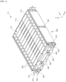
- FIG. 1 is a diagram illustrating a battery block 10 according to one embodiment of the present invention
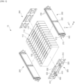
- FIG. 2 is an exploded perspective view of the battery block 10 of FIG. 1
- a battery block 10 according to the present invention includes a pair of side plates 200 and a pair of end plates 300 that are coupled thereto to form a parallelepiped-shaped space, and a cell array 100 housed in the parallelepiped space.
- the cell array 100 refers to a population of cells comprising a plurality of prismatic cells 110 arranged in a row.
- Each prismatic cell 110 is a finished prismatic secondary battery capable of being independently charged and discharged, and in the embodiment shown, 12 prismatic cells 110 are shown together to form a single cell array 100. All of the prismatic cells 110 are typically constructed to the same specifications, and the prismatic cells 110 aligned in a row collectively form a parallelepiped shape.
- the illustrated prismatic cell 110 corresponds to a unidirectional prismatic cell 110 having both positive and negative electrode terminals 112 disposed on its upper surface, and further having a venting device 114 between the pair of electrode terminals 112.
- the venting device 114 provided on the upper surface of the plurality of prismatic cells 110 arranged in the cell array 100 is also aligned in a row.
- the venting device 114 is a device corresponding to a safety valve that ruptures to relieve the pressure inside the prismatic cell 110 when an exceed level of pressure is applied, and may include, for example, a notched rupture disk made of a thin plate-like member of a metal material.
- a notched rupture disk made of a thin plate-like member of a metal material.
- a pair of side plates 200 are disposed on each of both sides of the cell array 100, and a pair of end plates 300 are disposed on each of the front and rear surfaces of the cell array 100. Both ends of the end plate 300 in the width direction W are fixed to side bracket 210 provided at both ends in the longitudinal direction L of the side plate 200, and the interconnection of the end plate 300 and the side plate 200 via the side bracket 210 constrains the cell array 100 as a single block.
- the side plate 200 and the end plate 300, and the side bracket 210 connecting them are all made of a thermally conductive material, for example, a metal material with good thermal conductivity, such as aluminum or stainless steel (SUS), through which the side plate 200 and the end plate 300 are thermally connected.
- a thermally conductive material for example, a metal material with good thermal conductivity, such as aluminum or stainless steel (SUS), through which the side plate 200 and the end plate 300 are thermally connected.
- SUS stainless steel
- the side plate 200 and end plate 300 that contact the cell array 100, as well as other neighboring prismatic cells 110 form a single thermal mass that is thermally connected to each other.
- the entire battery block 10 forms a single thermal mass, which provides the basis for a passive cooling structure that not only mitigates the rapid temperature rise of the prismatic cells 110 during charging and discharging, but also quickly disperses heat in the event of an emergency such as thermal runaway, thermal propagation, and the like.
- the upper end of the side plate 200 has a bent upper flange 230 that contacts the upper surface of the cell array 100.
- the upper flange 230 creates a downward fixing force that presses the cell array 100 to the bottom when the side plate 200 and end plate 300 of the battery block 10 are mounted to the mounting part 640 of the pack case 602.
- the side bracket 210 provided at both ends of the side plate 200 include fastening grooves 212 that are inserted into a weld bolt 310 protruding from the end plate 300, and the weld bolt 310 and the fastening grooves 212 are bonded to each other by welding.
- the weld bolts 310 and the fastening grooves 212 may be provided in an up-down pair relative to the center in the height direction H of the cell array 100.
- end plate 300 includes an end bracket 400 that is fixed to the pack case 602.
- side bracket 210 also includes end bracket 400 that is fixed to the pack case 602.
- An end bracket 400 provided on the end plate 300 and the side plate 200 has a fastening surface 410 aligned with the width direction W, and one or more fastening holes 412 are formed on the fastening surface 410 of the end bracket 400.
- the fastening surface 410 of the end bracket 400 is seated on a mounting part 640 provided in the pack case 602 (see FIG. 9 ), and the battery block 10 is fixed to the pack case 602 by bonding or uniting the end bracket 400 to the mounting part 640 of the pack case 602 via the fastening holes 412.
- the end bracket 400 may include reinforcing ribs 420, such as in the form of a right triangle perpendicular to the fastening surface 410, to reinforce rigidity to a load in the height direction.
- reinforcing ribs 420 such as in the form of a right triangle perpendicular to the fastening surface 410, to reinforce rigidity to a load in the height direction.
- one or more concave surfaces 320 similar to the concave surface 222 of the side plate 200, may be bent and formed, and the upper end of the end plate 300 may also be provided with an upper flange 330 for stable fixation of the cell array 100.
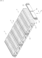
- FIG. 3 is a diagram illustrating a structure in which the battery block 10 extends in the width direction W to form a battery module 500 connected together.
- the battery block 10 of the present invention is capable of extending any number of cell arrays 100 along the width direction W via the side plate 200 and side bracket 210.
- the side bracket210 is provided with fastening grooves 212 on both the left and right sides relative to the center in the width direction W of the side plate 200.
- fastening grooves 212 on both the left and right sides relative to the center in the width direction W of the side plate 200.
- Another cell array 100 arranged along the width direction W share a single side plate 200 in the center, and a plurality of cell arrays 100 extend along the width direction W by means of a weld bolt 310 provided in a pair of end plates 300 disposed at the front and rear surfaces of another array of cells 100, respectively, fixed to the fastening grooves 212 of the side bracket 210.
- the side bracket 210 is provided with fastening grooves 212 on both the left and right sides, respectively, it becomes possible to couple one end plate 300 with each side of one side plate 200, and as neighboring cell arrays 100 share one side plate 200, the total number of side plates 200 is only one more than the number of cell arrays 100 in a structure in which a plurality of battery blocks 10 are connected.
- the space efficiency of the battery pack 600 mounting the battery block 10 of the present invention is further improved.
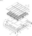
- FIG. 4 illustrates a structure in which the battery block 10 extending in the width direction W described in the first embodiment is mounted in a pack case 602.
- the pack case 602 in which the plurality of battery blocks 10 is mounted, includes a base plate 610 forming a bottom surface, a side frame 620 forming walls along all sides of the base plate 610, and an upper cover 630 sealing the upper surface of the pack case 602.
- the pack case 602 shown illustrates an example of two battery modules 500 with the side plate 200 and end plate 300 coupled together in a grid configuration to form a row of three cell arrays 100 (as used herein, an assembly of a plurality of battery blocks connected together via side plates will be referred to as a battery module).
- a single battery module 500 with three cell arrays 100 arranged in a row has an end bracket 400 exposed along the end plate 300 at the front and rear surfaces, and one end bracket 400 also exposed on the side bracket 210 between the end plates 300.
- the pack case 602 is also provided with a rail-like mounting part 640 corresponding to the fastening surface 410 of the end bracket 400 that protrude from the front and rear surfaces of the battery module 500.
- the mounting part 640 includes a pair of side mounting parts 642 coupled to or integrally formed with the side frame 620, and a center mounting part 644 arranged side by side across the center of the base plate 610.
- the fastening surface 410 of the end bracket 400 faces the mounting part 640 of the pack case 602, and all of the battery blocks 10 are fixed to the pack case 602 by bonding or uniting the end bracket 400 to the mounting part 640 of the pack case 602 via the fastening holes 412.
- the base plate 610 includes a heat sink 612 provided with a cooling flow path 614 through which cooling medium flows therein.
- the heat sink 612 includes a lower plate with the cooling flow path 614 formed therein, and an upper plate that fluidly seals by bonding to the lower plate, the upper plate having a pair of flow adapters 616 that form inlets and outlets for cooling medium to be distributed to the cooling flow path 614.
- thermally conductive thermal interface material refers to an air-permeable material that has a significantly higher thermal conductivity than metallic materials such as aluminum, and the thermally conductive thermal interface material 618 contributes to rapidly transferring heat generated by the battery block 10 to the heat sink 612 with a high thermal conductivity and by acting as a filler to smooth out microscopic irregularities in the contact surface.
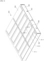
- the battery modules 500 mounted within the pack case 602 are sealed by an upper cover 630 that couples to the upper end corner of the side frame 620, as shown in FIG. 5 .
- the battery pack 600 of the present invention has a venting duct 632 integrally formed with the upper cover 630.
- the venting duct 632 has a flow path communicating with a plurality of venting devices 114 arranged in a row with the upper surface of the cell array 100.
- the venting duct 632 is formed integrally with the upper cover 630 by plastic processing, such as press processing.
- plastic processing such as press processing.
- the upper cover 630 is bent to form a curved cross-sectional shape, which provides the upper cover 630 with increased mechanical rigidity and better protection of the battery block 10 inside the pack case 602 compared to a conventional upper cover that is simply a flat plate.
- FIGS. 6 through 7 are cross-sectional views of the upper cover 630 cut through to illustrate the cross-sectional structure of the venting duct 632.
- the venting duct 632 includes a concave part 634 coupled to the upper surface of the prismatic cell 110 around the venting device 114, and a convex part 633 that forms a space surrounding the venting device 114.
- the concave part 634 and the convex part 633 are referred to with reference to their relative depth differences when the upper cover 630 is viewed from above, and it can be understood that the plane formed by the surface of the convex part 633 corresponds to a reference surface of the upper cover 630.
- the contact surface of the concave part 634 of the venting duct 632 and the upper surface of the prismatic cell 110 may be interposed with a heat-resistant insulating sheet 636, such as a mica sheet, to prevent the venting device 114 from being covered.
- the insulating sheet 636 thermally protects the contact surface of the concave part 634 and the prismatic cell 110 when high temperature gases, flames, particles, etc. are ejected by the rupture of the venting device 114, and allows the airtightness to be maintained longer.
- each cell array 100 has one venting duct 632. That is, the plurality of prismatic cells 110 comprising the cell array 100 share one venting duct 632, and the venting duct 632 assigned to each cell array 100 is separate from each other. In this way, thermal runaway generated in any one battery block 10 is inhibited from propagating to the surrounding area, thereby preventing or delaying it from spreading to thermal propagation.
- the convex part 633 of the venting duct 632 has one side facing the side frame 620 of the pack case 602 forming a duct outlet 635, while the opposite side forms a closed surface. Referring to FIGS. 6 and 8 , one end of the convex part 633 adjacent to the side frame 620 is open, while the other end opposite is closed. Accordingly, combustion products flowing through the venting duct 632 are directed to flow in one direction toward the side frame 620.
- the duct outlet 635 of the convex part 633 is in communication with the venting outlet 622 provided in the side frame 620 of the pack case 602, so that the combustion products ejected from any battery block 10 follow a predetermined path and finally discharge to the venting outlet 622 of the pack case 602.
- combustion products from the prismatic cells 110 that have undergone thermal runaway can be discharged to the outside of the pack case 602 via a limited and defined pathway, thereby allowing for efficient safety design of the battery pack 600 as well as the various devices mounting the battery pack 600.
- the upper surface of the prismatic cell 110 has electrode terminals 112 on each side of the venting device 114. Since the electrical wiring between the plurality of prismatic cells 110 comprising the cell array 100 and the battery block 10 originates from the electrode terminals 112, it is necessary to secure the space required for the electrical wiring around the electrode terminals 112.
- the upper cover 630 is provided with a wiring duct 638 on either side of the venting duct 632 to form a space surrounding the electrode terminals 112 of the cell array 100, and the wiring duct 638 is preferably formed integrally by plastically processing the upper cover 630.
- the wiring duct 638 is isolated from the entirety of the venting duct 632, including the duct outlet 635. That is, the wiring duct 638 is isolated from the venting duct 632 to protect the electrical wiring from combustion products flowing through the venting duct 632 in the event of a thermal runaway event in which the venting device 114 is activated.
- one end of the wiring duct 638 adjacent to the side frame 620 is not in line with the outlet cross-section of the duct outlet 635, thereby preventing the electrical wiring within the wiring duct 638 from being exposed to high temperature combustion products discharged through the duct outlet 635.
- FIG. 9 is a diagram illustrating a battery block 10 according to a third embodiment, wherein the battery block 10 in third embodiment is provided with a heat-absorbing/venting pouch 240 as a safety means against various thermal issues.
- the heat-absorbing/venting pouch 240 can be disposed inside the side plate 200 and/or on the front and rear surfaces of the prismatic cell 110.
- the side plate 200 shown consists of a single plate bent into a "U” shape with an open upper end to form an internal space.
- the side plate 200 is lightweight and exhibits good mechanical strength.
- the side plate 200 has concave surfaces 222 on either side of the bent plate, and the facing concave surfaces 222 are bonded to each other to form bonding ribs 220.
- These bonding ribs 220 are provided at least one along the longitudinal direction L of the side plate 200, and in the embodiment shown, a total of three bonding ribs 220 are formed at each end and in the center of the side plate 200.
- a single plate bent in a "U" shape may have excellent durability and strength against compression and tension in the longitudinal direction L due to the bending structure, but may be relatively weak against forces in the height direction H.
- the bonding ribs 220 improve the rigidity of the side plate 200 to the force in the height direction H by connecting the concave surface 222 on both sides of the side plate 200 together by bonding through welding, riveting, or the like.
- the side plate 200 By such a structure of the side plate 200, i.e., a single plate structure bent in a "U" shape and a structure of the concave surface 222 bonded to each other, the side plate 200 is lightweight and has strong mechanical rigidity. Accordingly, in the battery block 10 of the present invention, the side plate 200 replaces the configuration of the cross beam conventionally provided in the battery pack 600, and the simplified structure of the battery pack 600 enables the space utilization rate of the battery pack 600 to be improved, further increasing the energy density in the same volume, and reducing the cost.
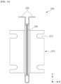
- FIG. 9 and in FIG. 11 which is a cross-sectional view cut along line "E-E" in FIG. 9 , one or more heat-absorbing/venting pouches 240 are inserted and built in the side plate 200. That is, a narrow, elongated space is provided within the side plate 200 by a pair of concave surfaces 222 that locally form the bonding ribs 220, into which the heat-absorbing/venting pouches 240 are inserted. In the embodiment shown, a total of three bonding ribs 220 are formed at each end and in the center of the side plate 200 to create two compartmentalized spaces, each of which contains a single heat-absorbing/venting pouch 240.
- the heat-absorbing/venting pouch 240 seals and stores an absorbent material 242 impregnated with a large amount of liquid, and the liquid impregnated with the absorbent material 242 absorbs the heat of the prismatic cell 110 transferred through the side plate 200.
- the heat-absorbing/venting pouch 240 has a heat capacity corresponding to the absorbed heat of the liquid impregnated with the absorbent material 242 and the latent heat that the liquid absorbs as it vaporizes when it exceeds its boiling point.
- the absorbed heat and latent heat of the liquid adds significant heat capacity to the side plate 200, allowing it to absorb more heat from the prismatic cell 110, further delaying the temperature rise of the prismatic cell 110.
- the body of the heat-absorbing/venting pouch 240 may be manufactured using a flexible laminate sheet, which may be a three-or-more layer structure including an aluminum thin film layer, an inner resin layer formed on the inner side of the aluminum thin film layer, and an outer resin layer formed on the outer side of the aluminum thin film layer.
- the inner resin layer may be unstretched casted polypropylene (CPP) or polypropylene (PP), and the outer resin layer may be polyethylene terephthalate (PET) or nylon.
- the heat-absorbing/venting pouch 240 when the liquid impregnated in a large amount in the absorbent material 242 contained in the heat-absorbing/venting pouch 240 absorbs the heat generated by the prismatic cell 110 and its temperature exceeds the boiling point and vaporizes, the rapid increase in volume due to the phase change from liquid to gas causes the heat-absorbing/venting pouch 240, which seals the absorbent material 242, to be under pressure. If the internal pressure exceeds the bursting strength of the heat-absorbing/venting pouch 240, a portion of the heat-absorbing/venting pouch 240 tears, releasing vapor. This discharge(venting) of the vapor allows the high-temperature prismatic cell 110 to cool once again.
- the heat-absorbing/venting pouch 240 may be configured such that the vapor that is discharged is appropriately directed so that it performs an effective cooling action.
- a portion of the heat-fused sealing part 244 formed along the edge of the heat-absorbing/venting pouch 240 may be provided with a vulnerable part 246.
- the vulnerable part 246 is configured to preferentially fracture under increased pressure due to vaporization of the liquid by locally reducing the seal strength of the heat-fused sealing part 244. That is, the vulnerable part 246 may be formed in a manner that makes the heat fusion strength of the heat-fused sealing part 244 lower than the surrounding area.
- the vulnerable part 246 can be made relatively thinner in thickness than the surrounding area or notched to reduce its strength, or it can be formed by locally removing the aluminum thin film layer that maintains the durability of the laminate sheet.
- the absorbent material 242 may be an absorbent material 242 including a superabsorbent matrix, such as a superabsorbent polymer (SAP) or a superabsorbent fiber (SAF).
- a superabsorbent matrix such as a superabsorbent polymer (SAP) or a superabsorbent fiber (SAF).
- SAP superabsorbent polymer
- SAF superabsorbent fiber
- superabsorbent matrices can be porous or fibrous, capable of absorbing large amounts of liquid by exhibiting capillary action, while superabsorbent fibers can be manufactured in the form of fibers, such as nonwoven fabrics, by processing superabsorbent resins.
- the superabsorbent matrix can significantly increase the heat capacity of the side plate 200 as it can hold a large amount of liquid.
- superabsorbent resins and superabsorbent fibers made therefrom are not particularly limited in the present invention, but can be used without limitation as long as they have a high absorption capacity for fluids, in particular water.
- superabsorbent resins in the present invention include one or more selected from the group consisting of polyacrylic acid, polyacrylate, polyacrylate graft polymers, starch, cross-linked carboxymethylated cellulose, acrylic acid copolymers, hydrolyzed starch-acrylonitrile graft copolymers, starch-acrylic acid graft copolymers, saponified vinyl acetate-acrylic acid ester copolymer, hydrolyzed acrylonitrile copolymer, hydrolyzed acrylamide copolymer, ethylene-maleic anhydride copolymer, isobutylene-maleic anhydride copolymer, polyvinyl sulfonic acid, polyvinylphosphonic acid, polyvinyl phosphoric acid, polyviny
- the type of acrylic acid copolymer used as a superabsorbent resin in the present invention is not particularly limited, but may preferably be a copolymer including one or more comonomers selected from the group consisting of acrylic acid monomer and maleic acid, itaconic acid, acrylamide, 2-acrylamide-2-methylpropanesulfonic acid, 2-(meth)acryloylethanesulfonic acid, 2-hydroxyethyl(meth)acrylate, and styrenesulfonic acid.
- the superabsorbent resin may have an absorption capacity for water of 10 g/g to 500 g/g, preferably 50 g/g to 200 g/g, but is not limited thereto. That is, each gram of the superabsorbent resin may absorb 10 g to 500 g of water, preferably 50 g to 200 g of water.
- the liquid impregnated in the absorbent material 242 may be water.
- Water has the largest specific heat and latent heat of any readily available liquid. Therefore, water impregnated in the absorbent material 242 is suitable for application in the heat-absorbing/venting pouch 240 of the present invention because it absorbs a large amount of heat during its phase change to a gas, beginning even before it is vaporized.
- the heat-absorbing/venting pouches 240 may be disposed between the prismatic cells 110 to contact the front and rear surfaces of a plurality of prismatic cells 110 comprising the cell array 100, and also on the front or rear surface of the outermost prismatic cell 110 (hereinafter referred to as "between the prismatic cells" for simplicity).
- the front and rear surfaces of the prismatic cells 110 may be contacted by the heat-absorbing/venting pouches 240 to more directly absorb heat from the prismatic cells 110, thereby more effectively compensating for thermal issues in the battery block 10.
- the configuration of the heat-absorbing/venting pouch 240 disposed between the prismatic cells 110 follows the same as described above, except that the location of the vulnerable part 246 on the heat-fused sealing part 244 can be limited to the upper end edge.
- the insulating sheet 636 may have a venting slit 637 penetrated at a location corresponding to the vulnerable part 246 of the heat-absorbing/venting pouch 240.
- the venting slit 637 is intended to provide a flow path for vapor ejected through the vulnerable part 246, and for effective cooling of the combustion products, the vulnerable part 246 and the corresponding venting slit 637 need to be located within the flow space formed by the convex part 633 of the venting duct 632.
Landscapes
- Chemical & Material Sciences (AREA)
- Chemical Kinetics & Catalysis (AREA)
- Electrochemistry (AREA)
- General Chemical & Material Sciences (AREA)
- Engineering & Computer Science (AREA)
- Manufacturing & Machinery (AREA)
- Battery Mounting, Suspending (AREA)
- Gas Exhaust Devices For Batteries (AREA)
Applications Claiming Priority (2)
| Application Number | Priority Date | Filing Date | Title |
|---|---|---|---|
| KR1020220168749A KR20240084197A (ko) | 2022-12-06 | 2022-12-06 | 커버 일체형 벤팅덕트를 구비하는 배터리 팩 |
| PCT/KR2023/019191 WO2024122954A1 (ko) | 2022-12-06 | 2023-11-27 | 커버 일체형 벤팅덕트를 구비하는 배터리 팩 |
Publications (3)
| Publication Number | Publication Date |
|---|---|
| EP4468497A1 true EP4468497A1 (de) | 2024-11-27 |
| EP4468497A4 EP4468497A4 (de) | 2025-06-18 |
| EP4468497B1 EP4468497B1 (de) | 2026-04-01 |
Family
ID=91379546
Family Applications (1)
| Application Number | Title | Priority Date | Filing Date |
|---|---|---|---|
| EP23900973.1A Active EP4468497B1 (de) | 2022-12-06 | 2023-11-27 | Batteriepack mit abdeckungsintegriertem entlüftungskanal |
Country Status (6)
| Country | Link |
|---|---|
| US (1) | US20250183420A1 (de) |
| EP (1) | EP4468497B1 (de) |
| JP (1) | JP2025508451A (de) |
| KR (1) | KR20240084197A (de) |
| CN (1) | CN118805294A (de) |
| WO (1) | WO2024122954A1 (de) |
Cited By (1)
| Publication number | Priority date | Publication date | Assignee | Title |
|---|---|---|---|---|
| EP4318739A4 (de) * | 2022-04-18 | 2025-05-21 | Lg Energy Solution, Ltd. | Batteriepack |
Family Cites Families (13)
| Publication number | Priority date | Publication date | Assignee | Title |
|---|---|---|---|---|
| JP2002134078A (ja) * | 2000-10-26 | 2002-05-10 | Toyota Motor Corp | 集合電池パック |
| US20100028758A1 (en) * | 2008-08-04 | 2010-02-04 | Eaves Stephen S | Suppression of battery thermal runaway |
| KR101191660B1 (ko) * | 2010-11-08 | 2012-10-17 | 에스비리모티브 주식회사 | 전지 모듈 |
| KR101199217B1 (ko) * | 2010-11-11 | 2012-11-07 | 에스비리모티브 주식회사 | 배터리 모듈 |
| WO2012133710A1 (ja) * | 2011-03-31 | 2012-10-04 | 三洋電機株式会社 | 電源装置及びこれを備える車両 |
| WO2012133709A1 (ja) * | 2011-03-31 | 2012-10-04 | 三洋電機株式会社 | 電源装置及び電源装置を備える車両 |
| JP2012221717A (ja) * | 2011-04-08 | 2012-11-12 | Panasonic Corp | 電池モジュール |
| CN207587926U (zh) * | 2016-11-29 | 2018-07-06 | 北京科易动力科技有限公司 | 电池模块的吸热隔热结构 |
| CN209104230U (zh) * | 2018-12-27 | 2019-07-12 | 宁德时代新能源科技股份有限公司 | 一种电池箱 |
| US11735795B2 (en) * | 2019-09-05 | 2023-08-22 | Samsung Sdi Co., Ltd. | Energy storage module |
| KR102754905B1 (ko) | 2020-04-14 | 2025-01-13 | 주식회사 엘지에너지솔루션 | 전지 팩 및 이를 포함하는 디바이스 |
| KR102919208B1 (ko) * | 2021-03-23 | 2026-01-27 | 주식회사 엘지에너지솔루션 | 냉각수를 활용한 배터리 셀의 열확산 방지 구조를 갖춘 배터리 모듈 및 이를 포함하는 배터리 팩 |
| KR102559379B1 (ko) | 2021-06-17 | 2023-07-26 | 한국전력공사 | 전주용 발판장치 |
-
2022
- 2022-12-06 KR KR1020220168749A patent/KR20240084197A/ko active Pending
-
2023
- 2023-11-27 CN CN202380023663.2A patent/CN118805294A/zh active Pending
- 2023-11-27 JP JP2024549203A patent/JP2025508451A/ja active Pending
- 2023-11-27 US US18/841,546 patent/US20250183420A1/en active Pending
- 2023-11-27 EP EP23900973.1A patent/EP4468497B1/de active Active
- 2023-11-27 WO PCT/KR2023/019191 patent/WO2024122954A1/ko not_active Ceased
Cited By (1)
| Publication number | Priority date | Publication date | Assignee | Title |
|---|---|---|---|---|
| EP4318739A4 (de) * | 2022-04-18 | 2025-05-21 | Lg Energy Solution, Ltd. | Batteriepack |
Also Published As
| Publication number | Publication date |
|---|---|
| WO2024122954A1 (ko) | 2024-06-13 |
| EP4468497B1 (de) | 2026-04-01 |
| US20250183420A1 (en) | 2025-06-05 |
| CN118805294A (zh) | 2024-10-18 |
| EP4468497A4 (de) | 2025-06-18 |
| KR20240084197A (ko) | 2024-06-13 |
| JP2025508451A (ja) | 2025-03-26 |
Similar Documents
| Publication | Publication Date | Title |
|---|---|---|
| JP7414990B2 (ja) | バッテリーモジュールの熱拡散防止構造を適用したバッテリーパック | |
| JP7482996B2 (ja) | 電池パックおよびこれを含むデバイス | |
| JP7374310B2 (ja) | 電池パックおよびこれを含むデバイス | |
| KR102922132B1 (ko) | 전지팩 및 이를 포함하는 디바이스 | |
| JP7483028B2 (ja) | 電池パックおよびこれを含むデバイス | |
| JP7384532B2 (ja) | 電池パックおよびこれを含むデバイス | |
| JP7274664B2 (ja) | バッテリーモジュール間の熱拡散防止構造を適用したバッテリーパック | |
| EP4329048B1 (de) | Prismatische sekundärbatterie | |
| KR102880677B1 (ko) | 배터리 모듈 및, 이를 포함하는 배터리 팩 및 이를 포함하는 자동차 | |
| EP4350846B1 (de) | Endotherme beutelanordnung für sekundärbatterie | |
| EP4325635B1 (de) | Batteriepack mit verbesserter kühlleistung | |
| JP2023514221A (ja) | 電池パックおよびこれを含むデバイス | |
| EP4468497B1 (de) | Batteriepack mit abdeckungsintegriertem entlüftungskanal | |
| US20240387917A1 (en) | Prismatic secondary battery | |
| KR20240084332A (ko) | 유도 벤팅구조를 구비한 배터리 팩 | |
| EP4465418B1 (de) | Batteriepack mit passiver wärmeableitungskühlstruktur | |
| EP4318739A1 (de) | Batteriepack | |
| KR20240098779A (ko) | 열 전파 지연에 효과적인 배터리 팩 | |
| KR20240084194A (ko) | 냉간운전 성능이 향상된 배터리 블록 | |
| US20260088422A1 (en) | Battery module, and battery pack and vehicle including same | |
| CN117296188A (zh) | 电池组 |
Legal Events
| Date | Code | Title | Description |
|---|---|---|---|
| STAA | Information on the status of an ep patent application or granted ep patent |
Free format text: STATUS: THE INTERNATIONAL PUBLICATION HAS BEEN MADE |
|
| PUAI | Public reference made under article 153(3) epc to a published international application that has entered the european phase |
Free format text: ORIGINAL CODE: 0009012 |
|
| STAA | Information on the status of an ep patent application or granted ep patent |
Free format text: STATUS: REQUEST FOR EXAMINATION WAS MADE |
|
| 17P | Request for examination filed |
Effective date: 20240823 |
|
| AK | Designated contracting states |
Kind code of ref document: A1 Designated state(s): AL AT BE BG CH CY CZ DE DK EE ES FI FR GB GR HR HU IE IS IT LI LT LU LV MC ME MK MT NL NO PL PT RO RS SE SI SK SM TR |
|
| A4 | Supplementary search report drawn up and despatched |
Effective date: 20250515 |
|
| RIC1 | Information provided on ipc code assigned before grant |
Ipc: H01M 50/342 20210101ALI20250509BHEP Ipc: H01M 10/658 20140101ALI20250509BHEP Ipc: H01M 50/209 20210101ALI20250509BHEP Ipc: H01M 50/264 20210101ALI20250509BHEP Ipc: H01M 50/24 20210101ALI20250509BHEP Ipc: H01M 50/358 20210101AFI20250509BHEP |
|
| GRAP | Despatch of communication of intention to grant a patent |
Free format text: ORIGINAL CODE: EPIDOSNIGR1 |
|
| STAA | Information on the status of an ep patent application or granted ep patent |
Free format text: STATUS: GRANT OF PATENT IS INTENDED |
|
| DAV | Request for validation of the european patent (deleted) | ||
| DAX | Request for extension of the european patent (deleted) | ||
| INTG | Intention to grant announced |
Effective date: 20260121 |
|
| GRAS | Grant fee paid |
Free format text: ORIGINAL CODE: EPIDOSNIGR3 |
|
| GRAA | (expected) grant |
Free format text: ORIGINAL CODE: 0009210 |
|
| STAA | Information on the status of an ep patent application or granted ep patent |
Free format text: STATUS: THE PATENT HAS BEEN GRANTED |
|
| P01 | Opt-out of the competence of the unified patent court (upc) registered |
Free format text: CASE NUMBER: UPC_APP_0003967_4468497/2026 Effective date: 20260203 |
|
| AK | Designated contracting states |
Kind code of ref document: B1 Designated state(s): AL AT BE BG CH CY CZ DE DK EE ES FI FR GB GR HR HU IE IS IT LI LT LU LV MC ME MK MT NL NO PL PT RO RS SE SI SK SM TR |
|
| REG | Reference to a national code |
Ref country code: CH Ref legal event code: F10 Free format text: ST27 STATUS EVENT CODE: U-0-0-F10-F00 (AS PROVIDED BY THE NATIONAL OFFICE) Effective date: 20260401 Ref country code: GB Ref legal event code: FG4D |
|
| REG | Reference to a national code |
Ref country code: DE Ref legal event code: R096 Ref document number: 602023014676 Country of ref document: DE |
|
| REG | Reference to a national code |
Ref country code: IE Ref legal event code: FG4D |