EP4468569A1 - Ensembles d'enroulement et procédés associés - Google Patents
Ensembles d'enroulement et procédés associés Download PDFInfo
- Publication number
- EP4468569A1 EP4468569A1 EP23382501.7A EP23382501A EP4468569A1 EP 4468569 A1 EP4468569 A1 EP 4468569A1 EP 23382501 A EP23382501 A EP 23382501A EP 4468569 A1 EP4468569 A1 EP 4468569A1
- Authority
- EP
- European Patent Office
- Prior art keywords
- winding
- stator
- winding body
- stator tooth
- strands
- Prior art date
- Legal status (The legal status is an assumption and is not a legal conclusion. Google has not performed a legal analysis and makes no representation as to the accuracy of the status listed.)
- Pending
Links
Images



Classifications
-
- H—ELECTRICITY
- H02—GENERATION; CONVERSION OR DISTRIBUTION OF ELECTRIC POWER
- H02K—DYNAMO-ELECTRIC MACHINES
- H02K3/00—Details of windings
- H02K3/04—Windings characterised by the conductor shape, form or construction, e.g. with bar conductors
- H02K3/18—Windings for salient poles
-
- H—ELECTRICITY
- H02—GENERATION; CONVERSION OR DISTRIBUTION OF ELECTRIC POWER
- H02K—DYNAMO-ELECTRIC MACHINES
- H02K3/00—Details of windings
- H02K3/04—Windings characterised by the conductor shape, form or construction, e.g. with bar conductors
- H02K3/28—Layout of windings or of connections between windings
-
- F—MECHANICAL ENGINEERING; LIGHTING; HEATING; WEAPONS; BLASTING
- F03—MACHINES OR ENGINES FOR LIQUIDS; WIND, SPRING, OR WEIGHT MOTORS; PRODUCING MECHANICAL POWER OR A REACTIVE PROPULSIVE THRUST, NOT OTHERWISE PROVIDED FOR
- F03D—WIND MOTORS
- F03D9/00—Adaptations of wind motors for special use; Combinations of wind motors with apparatus driven thereby; Wind motors specially adapted for installation in particular locations
- F03D9/20—Wind motors characterised by the driven apparatus
- F03D9/25—Wind motors characterised by the driven apparatus the apparatus being an electrical generator
-
- H—ELECTRICITY
- H02—GENERATION; CONVERSION OR DISTRIBUTION OF ELECTRIC POWER
- H02K—DYNAMO-ELECTRIC MACHINES
- H02K1/00—Details of the magnetic circuit
- H02K1/06—Details of the magnetic circuit characterised by the shape, form or construction
- H02K1/12—Stationary parts of the magnetic circuit
- H02K1/14—Stator cores with salient poles
- H02K1/146—Stator cores with salient poles consisting of a generally annular yoke with salient poles
- H02K1/148—Sectional cores
-
- H—ELECTRICITY
- H02—GENERATION; CONVERSION OR DISTRIBUTION OF ELECTRIC POWER
- H02K—DYNAMO-ELECTRIC MACHINES
- H02K15/00—Processes or apparatus specially adapted for manufacturing, assembling, maintaining or repairing of dynamo-electric machines
- H02K15/02—Processes or apparatus specially adapted for manufacturing, assembling, maintaining or repairing of dynamo-electric machines of stator or rotor bodies
- H02K15/021—Magnetic cores
- H02K15/022—Magnetic cores with salient poles
-
- H—ELECTRICITY
- H02—GENERATION; CONVERSION OR DISTRIBUTION OF ELECTRIC POWER
- H02K—DYNAMO-ELECTRIC MACHINES
- H02K21/00—Synchronous motors having permanent magnets; Synchronous generators having permanent magnets
- H02K21/12—Synchronous motors having permanent magnets; Synchronous generators having permanent magnets with stationary armatures and rotating magnets
-
- H—ELECTRICITY
- H02—GENERATION; CONVERSION OR DISTRIBUTION OF ELECTRIC POWER
- H02K—DYNAMO-ELECTRIC MACHINES
- H02K3/00—Details of windings
- H02K3/04—Windings characterised by the conductor shape, form or construction, e.g. with bar conductors
- H02K3/24—Windings characterised by the conductor shape, form or construction, e.g. with bar conductors with channels or ducts for cooling medium between the conductors
-
- H—ELECTRICITY
- H02—GENERATION; CONVERSION OR DISTRIBUTION OF ELECTRIC POWER
- H02K—DYNAMO-ELECTRIC MACHINES
- H02K3/00—Details of windings
- H02K3/32—Windings characterised by the shape, form or construction of the insulation
- H02K3/34—Windings characterised by the shape, form or construction of the insulation between conductors or between conductor and core, e.g. slot insulation
-
- H—ELECTRICITY
- H02—GENERATION; CONVERSION OR DISTRIBUTION OF ELECTRIC POWER
- H02K—DYNAMO-ELECTRIC MACHINES
- H02K3/00—Details of windings
- H02K3/46—Fastening of windings on the stator or rotor structure
- H02K3/52—Fastening salient pole windings or connections thereto
- H02K3/521—Fastening salient pole windings or connections thereto applicable to stators only
- H02K3/522—Fastening salient pole windings or connections thereto applicable to stators only for generally annular cores with salient poles
-
- H—ELECTRICITY
- H02—GENERATION; CONVERSION OR DISTRIBUTION OF ELECTRIC POWER
- H02K—DYNAMO-ELECTRIC MACHINES
- H02K7/00—Arrangements for handling mechanical energy structurally associated with dynamo-electric machines, e.g. structural association with mechanical driving motors or auxiliary dynamo-electric machines
- H02K7/18—Structural association of electric generators with mechanical driving motors, e.g. with turbines
- H02K7/1807—Rotary generators
- H02K7/1823—Rotary generators structurally associated with turbines or similar engines
- H02K7/183—Rotary generators structurally associated with turbines or similar engines wherein the turbine is a wind turbine
- H02K7/1838—Generators mounted in a nacelle or similar structure of a horizontal axis wind turbine
-
- H—ELECTRICITY
- H02—GENERATION; CONVERSION OR DISTRIBUTION OF ELECTRIC POWER
- H02K—DYNAMO-ELECTRIC MACHINES
- H02K2203/00—Specific aspects not provided for in the other groups of this subclass relating to the windings
- H02K2203/12—Machines characterised by the bobbins for supporting the windings
-
- H—ELECTRICITY
- H02—GENERATION; CONVERSION OR DISTRIBUTION OF ELECTRIC POWER
- H02K—DYNAMO-ELECTRIC MACHINES
- H02K2213/00—Specific aspects, not otherwise provided for and not covered by codes H02K2201/00 - H02K2211/00
- H02K2213/03—Machines characterised by numerical values, ranges, mathematical expressions or similar information
-
- Y—GENERAL TAGGING OF NEW TECHNOLOGICAL DEVELOPMENTS; GENERAL TAGGING OF CROSS-SECTIONAL TECHNOLOGIES SPANNING OVER SEVERAL SECTIONS OF THE IPC; TECHNICAL SUBJECTS COVERED BY FORMER USPC CROSS-REFERENCE ART COLLECTIONS [XRACs] AND DIGESTS
- Y02—TECHNOLOGIES OR APPLICATIONS FOR MITIGATION OR ADAPTATION AGAINST CLIMATE CHANGE
- Y02E—REDUCTION OF GREENHOUSE GAS [GHG] EMISSIONS, RELATED TO ENERGY GENERATION, TRANSMISSION OR DISTRIBUTION
- Y02E10/00—Energy generation through renewable energy sources
- Y02E10/70—Wind energy
Definitions
- the present disclosure relates to winding assemblies, and to pole shoes comprising such winding assemblies.
- the present disclosure further relates to electrical machines e.g. generators comprising such winding assemblies or pole shoes. And the present disclosure further relates to wind turbines comprising such a generator.
- the present disclosure also relates to methods for mounting winding assemblies to a stator tooth of an electrical machine.
- Wind turbines are commonly used to supply electricity into the electrical grid.
- Wind turbines of this kind generally comprise a tower and a rotor arranged on the tower.
- the rotor which typically comprises a hub and a plurality of blades, is set into rotation under the influence of the wind on the blades. Said rotation generates a torque that is normally transmitted through a rotor shaft to a generator, either directly (“directly driven” or “gearless”) or through the use of a gearbox. This way, the generator produces electricity which can be supplied to the electrical grid.
- Wind turbine generators and other electrical machines such as motors, generally comprise a rotor and a stator.
- Rotor and stator can be concentrically mounted with a radial air gap between them.
- the rotor rotates with respect to the stator.
- the rotor may form an inner structure and the stator the outer structure.
- the stator therefore may radially surround the rotor.
- the arrangement may be opposite, with the rotor radially surrounding the stator.
- PM permanent magnet excited generators
- winding elements i.e., coils
- a permanent magnet generator may comprise a stator yoke with a plurality of teeth protruding in a radial direction.
- the teeth may protrude towards a center of the stator yoke in generators where the stator surrounds the generator rotor.
- the teeth may protrude in a radial direction towards the outside of the stator yoke.
- a plurality of slots may be defined between adjacent teeth, wherein each slot may house a respective winding, or several parts of different windings.
- electrically excited generators generally comprise a rotor having a plurality of pole shoes and excitation windings, i.e., coils.
- a current is applied to the excitation coils.
- the applied current creates the polarity of the poles, wherein adjacent poles have a different magnetic polarity.
- the magnetic field from the pole shoes reaches the windings of the stator and causes a variable magnetic flux in the stator windings to produce a voltage in the stator windings.
- Windings are typically made of insulated copper wire and are wound around the teeth to produce the necessary electromagnetic fields.
- One of the main issues associated with windings in large electric machines is overheating. As current flows through the copper wire in the windings, it generates heat, which can build up and can cause the insulation to degrade and/or overall performance of the electrical machine to diminish. Overheating can result from a number of factors, including high current density, inadequate cooling, or poor quality insulation. Further, overheating can lead to insulation breakdown, which can result in short circuits and severe damage to the machine.
- insulation failure Another issue associated with windings is insulation failure.
- the insulation on the copper wire is essential for preventing short circuits and other electrical problems.
- insulating windings effectively implies that the insulating material has to be firmly secured around the winding surface. This results in the insulating material, e.g. insulation tape, being subjected to high loads e.g. at the corners of the winding. This excessive mechanical stress may promote insulation degradation over time. Insulation failure can also result in severe damage to the machine.
- Such potential issues can be aggravated with increasing size of the electrical machines.
- size of the electrical machines increase, so may the size of the stator teeth and the corresponding windings.
- large size electrical machines more particularly generators are known from direct drive wind turbines, and particularly direct drive wind turbines with a nominal power of 10 MW or more.
- Such direct drive generators may have a diameter of e.g. 6-8 meters or even more, and a length of 1 - 2 meters or even more.
- Large size electrical machines are also known in other technical fields, such as e.g. hydropower installations.
- the present disclosure aims to provides winding assemblies and associated methods which are also suitable for large or very large size electrical machines, and which at least partially overcome some of the aforementioned drawbacks.
- a winding assembly for a stator tooth of an electrical machine comprising a first winding body configured to be mounted around a section of the stator tooth that is near the base of the stator tooth, and comprising a plurality of first insulated strands wound around the stator tooth.
- the winding assembly further comprises a second winding body configured to be mounted closer to the distal end of the stator tooth than the first winding body and comprising a plurality of second insulated strands wound around the stator tooth. The second winding body is separated from the first winding body.
- each winding body may have an independent insulation, and therefore the insulation material may be subjected to less severe tension loads due to the reduced height of the body.
- the first and second winding bodies may be optimized for different purposes as will be explained herein.
- the temperature of the winding assembly disclosed may be controlled in a more efficient manner due to an increase in exterior surface area to volume ratio compared with single body winding. The physical separation of the winding bodies allows for additional cooling which will be explained hereinafter.
- a stator segment comprising one or more stator teeth extending from a base to a distal end in a radial direction.
- the stator segment further comprising a winding assembly according to examples of the previous aspect.
- an electrical machine comprises a rotor which is rotatable about a machine axis; and a stator which is concentric with respect to the rotor. And the stator comprises a plurality of pole shoes according to the previous aspect.
- a wind turbine comprising such an electrical machine is provided in a further aspect.
- a method for mounting a winding assembly to a stator tooth comprising providing a first winding body by winding a plurality of first insulated strands around a section of the stator tooth that is near the base of the stator tooth and providing a second winding body by winding a plurality of second insulated strands around a section of the stator tooth that is closer to the distal end of the stator tooth.
- the method further comprises electrically connecting the first winding body to the second winding body.
- a pole shoe for a stator of an electrical machine comprises a stator tooth extending from a base to a distal end in a radial direction, and wherein the base of the pole shoe is shaped such as to fit in a mating structure on the stator.
- the pole shoe further comprises a first winding body comprising a plurality of first insulated strands wound around a section of the stator tooth that is near the base of the stator tooth, and a second winding body comprising a plurality of second insulated strands wound around the stator tooth closer to the distal end of the stator tooth than the first winding body.
- the second winding body is separated from the first winding body, and the first winding body is electrically connected to the second winding body.
- strand may refer to both a wire, or cable, with a circular or rounded cross-section as well as to a plate like material with e.g. a rectangular, square or other cross-section.
- the plate like material may herein have a certain thickness and may be regarded e.g. as a strip or bar.
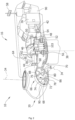
- Figure 1 is a perspective view of an example of a wind turbine 10.
- the wind turbine 10 is a horizontal-axis wind turbine.
- the wind turbine 10 may be a vertical-axis wind turbine.
- the wind turbine 10 includes a tower 15 that extends from a support system 14 on a ground 12, a nacelle 16 mounted on tower 15, and a rotor 18 that is coupled to nacelle 16.
- the rotor 18 includes a rotatable hub 20 and at least one rotor blade 22 coupled to and extending outward from the hub 20.
- the rotor 18 has three rotor blades 22.
- the rotor 18 includes more or less than three rotor blades 22.
- the tower 15 may be fabricated from tubular steel to define a cavity (not shown in figure 1 ) between a support system 14 and the nacelle 16.
- the tower 15 is any suitable type of a tower having any suitable height.
- the tower can be a hybrid tower comprising a portion made of concrete and a tubular steel portion.
- the tower can be a partial or full lattice tower.
- the rotor blades 22 are spaced about the hub 20 to facilitate rotating the rotor 18 to enable kinetic energy to be transferred from the wind into usable mechanical energy, and subsequently, electrical energy.
- the rotor blades 22 are mated to the hub 20 by coupling a blade root portion 24 to the hub 20 at a plurality of load transfer regions 26.
- the load transfer regions 26 may have a hub load transfer region and a blade load transfer region (both not shown in figure 1 ). Loads induced to the rotor blades 22 are transferred to the hub 20 via the load transfer regions 26.
- the rotor blades 22 may have a length ranging from about 15 meters (m) to about 90 m or more.
- Rotor blades 22 may have any suitable length that enables the wind turbine 10 to function as described herein.
- blade lengths include 20 m or less, 37 m, 48.7 m, 50.2m, 52.2 m or a length that is greater than 91 m.
- the rotor 18 is rotated about a rotor axis 30.
- the rotor blades 22 are also subjected to various forces and moments. As such, the rotor blades 22 may deflect and/or rotate from a neutral, or non-deflected, position to a deflected position.
- a pitch angle of the rotor blades 22, i.e., an angle that determines an orientation of the rotor blades 22 with respect to the wind direction, may be changed by a pitch system 32 to control the load and power generated by the wind turbine 10 by adjusting an angular position of at least one rotor blade 22 relative to wind vectors. Pitch axes 34 of rotor blades 22 are shown.
- the pitch system 32 may particularly change a pitch angle of the rotor blades 22 such that the angle of attack of (portions of) the rotor blades are reduced, which facilitates reducing a rotational speed and/or facilitates a stall of the rotor 18.
- a blade pitch of each rotor blade 22 is controlled individually by a wind turbine controller 36 or by a pitch control system 80.
- the blade pitch for all rotor blades 22 may be controlled simultaneously by said control systems.
- a yaw direction of the nacelle 16 may be rotated about a yaw axis 38 to position the rotor blades 22 with respect to wind direction 28.
- the wind turbine controller 36 is shown as being centralized within the nacelle 16, however, the wind turbine controller 36 may be a distributed system throughout the wind turbine 10, on the support system 14, within a wind farm, and/or at a remote-control center.
- the wind turbine controller 36 includes a processor 40 configured to perform the methods and/or steps described herein. Further, many of the other components described herein include a processor.
- processor is not limited to integrated circuits referred to in the art as a computer, but broadly refers to a controller, a microcontroller, a microcomputer, a programmable logic controller (PLC), an application specific, integrated circuit, and other programmable circuits, and these terms are used interchangeably herein. It should be understood that a processor and/or a control system can also include memory, input channels, and/or output channels.
- PLC programmable logic controller
- Figure 2 is an enlarged sectional view of a portion of the wind turbine 10.
- the wind turbine 10 includes the nacelle 16 and the rotor 18 that is rotatably coupled to the nacelle 16. More specifically, the hub 20 of the rotor 18 is rotatably coupled to an electric generator 42 positioned within the nacelle 16 by the main shaft 44, a gearbox 46, a high-speed shaft 48, and a coupling 50.
- the main shaft 44 is disposed at least partially coaxial to a longitudinal axis (not shown) of the nacelle 16.
- a rotation of the main shaft 44 drives the gearbox 46 that subsequently drives the high-speed shaft 48 by translating the relatively slow rotational movement of the rotor 18 and of the main shaft 44 into a relatively fast rotational movement of the high-speed shaft 48.
- the latter is connected to the generator 42 for generating electrical energy with the help of a coupling 50.
- a transformer 90 and/or suitable electronics, switches, and/or inverters may be arranged in the nacelle 16 in order to transform electrical energy generated by the generator 42 having a voltage between 400V to 1000 V into electrical energy having medium voltage (10 - 35 KV). Said electrical energy is conducted via power cables from the nacelle 16 into the tower 15.
- the main frame 52 is configured to carry the entire load caused by the weight of the rotor 18 and components of the nacelle 16 and by the wind and rotational loads, and furthermore, to introduce these loads into the tower 15 of the wind turbine 10.
- the rotor shaft 44, generator 42, gearbox 46, high speed shaft 48, coupling 50, and any associated fastening, support, and/or securing device including, but not limited to, support 52, and forward support bearing 60 and aft support bearing 62, are sometimes referred to as a drive train 64.
- the wind turbine may be a direct drive wind turbine without gearbox 46.
- Generator 42 operate at the same rotational speed as the rotor 18 in direct drive wind turbines. They therefore generally have a much larger diameter than generators used in wind turbines having a gearbox 46 for providing a similar amount of power than a wind turbine with a gearbox.
- the nacelle 16 may also include a yaw drive mechanism 56 that may be used to rotate the nacelle 16 and thereby also the rotor 18 about the yaw axis 38 to control the perspective of the rotor blades 22 with respect to the wind direction 28.
- a yaw drive mechanism 56 may be used to rotate the nacelle 16 and thereby also the rotor 18 about the yaw axis 38 to control the perspective of the rotor blades 22 with respect to the wind direction 28.
- the nacelle 16 may also include at least one meteorological measurement system 58 which may include a wind vane and anemometer.
- the meteorological measurement system 58 can provide information to the wind turbine controller 36 that may include wind direction 28 and/or wind speed.
- the pitch system 32 is at least partially arranged as a pitch assembly 66 in the hub 20.
- the pitch assembly 66 includes one or more pitch drive systems 68 and at least one sensor 70.
- Each pitch drive system 68 is coupled to a respective rotor blade 22 (shown in figure 1 ) for modulating the pitch angle of a rotor blade 22 along the pitch axis 34. Only one of three pitch drive systems 68 is shown in figure 2 .
- the pitch assembly 66 includes at least one pitch bearing 72 coupled to hub 20 and to a respective rotor blade 22 (shown in figure 1 ) for rotating the respective rotor blade 22 about the pitch axis 34.
- the pitch drive system 68 includes a pitch drive motor 74, a pitch drive gearbox 76, and a pitch drive pinion 78.
- the pitch drive motor 74 is coupled to the pitch drive gearbox 76 such that the pitch drive motor 74 imparts mechanical force to the pitch drive gearbox 76.
- the pitch drive gearbox 76 is coupled to the pitch drive pinion 78 such that the pitch drive pinion 78 is rotated by the pitch drive gearbox 76.
- the pitch bearing 72 is coupled to pitch drive pinion 78 such that the rotation of the pitch drive pinion 78 causes a rotation of the pitch bearing 72.
- Pitch drive system 68 is coupled to the wind turbine controller 36 for adjusting the pitch angle of a rotor blade 22 upon receipt of one or more signals from the wind turbine controller 36.
- the pitch drive motor 74 is any suitable motor driven by electrical power and/or a hydraulic system that enables pitch assembly 66 to function as described herein.
- the pitch assembly 66 may include any suitable structure, configuration, arrangement, and/or components such as, but not limited to, hydraulic cylinders, springs, and/or servomechanisms.
- the pitch drive motor 74 is driven by energy extracted from a rotational inertia of hub 20 and/or a stored energy source (not shown) that supplies energy to components of the wind turbine 10.
- the pitch assembly 66 may also include one or more pitch control systems 80 for controlling the pitch drive system 68 according to control signals from the wind turbine controller 36, in case of specific prioritized situations and/or during rotor 18 overspeed.
- the pitch assembly 66 includes at least one pitch control system 80 communicatively coupled to a respective pitch drive system 68 for controlling pitch drive system 68 independently from the wind turbine controller 36.
- the pitch control system 80 is coupled to the pitch drive system 68 and to a sensor 70.
- the wind turbine controller 36 may control the pitch drive system 68 to adjust a pitch angle of rotor blades 22.
- Figure 3 schematically illustrates a winding assembly 100 according to an example the present disclosure. More precisely, the winding assembly 100 in figure 3 is illustrated in a mounted configuration, i.e. the winding assembly 100 is mounted to a stator tooth 200 of an electrical machine.
- the stator tooth 200 may be attached to a remainder of the stator structure, e.g. a stator yoke through the bases 210 of each corresponding tooth.
- the distal end 220 of the tooth is arranged at a side of the air gap between the stator and rotor.
- the winding assembly 100 comprises a plurality of winding bodies 120, 130 comprising insulated strands 121, 131. Further, the plurality of winding bodies 120, 130 include a first winding body 120 configured to be mounted around a section of the stator tooth 200 that is near the base 21, and a second winding body 130 configured to be mounted closer to the distal end 220 of the stator tooth 200 than the first winding body 120. Additionally, the first and second winding bodies 120, 130 are electrically connected. In the example in figure 3 , the first and second winding bodies 120, 130 are electrically connected through a connector 160.
- the winding assembly 100 allows using winding bodies with lower height-to-width ratio than when a single winding body is used.
- the height-to-width ratio may be below 5 and more specifically below 3 for one or more of the winding bodies, so that insulation failure may be reduced.
- the winding assembly provided allows reducing the tension applied on the insulation material 122, 132 to secure it around the winding bodies 120, 130. This, at the same time, increases the resin content of the insulation around the corner the corners of the winding bodies 120, 130.
- the winding assembly 100 may further comprise a cooling channel 140 between the first and second winding bodies 120, 130.
- the cooling channel 140 may convey a liquid or gas coolant.
- the winding assembly 100 may comprise a third winding body electrically connected to the first and second winding bodies 120, 130.
- the third winding body may be configured to be mounted closer to the distal end 220 of the stator tooth 200 than the second winding body 130.
- additional cooling channels or circuits may be provided between respective additional winding bodies.
- the cooling channel between winding bodies may have different cooling characteristics depending on the winding bodies between which they are fitted.
- a cooling channel 140 between the first and second winding body 120, 130 may be configured to convey a liquid coolant and a cooling circuit between the second and third winding body may be configured to convey a cooling gas, e.g. air.
- cooling channels may be configured to convey the same fluid, and may have the same or different cooling flow rates.
- Figure 4 schematically illustrates a cross-section across the plane A-A' in figure 3 . Note that the cross-sections of the strands 121, 131 have not been illustrated with section lines for simplicity.
- a pole shoe may be provided as a separate unit which can be mounted to a stator structure.
- a pole shoe for a stator of an electrical machine may comprise a stator tooth and a winding assembly comprising multiple winding bodies according to any of the examples herein disclosed.
- the present disclosure provided a pole shore, wherein the pole shoe comprises a stator tooth 200 extending from a base 210 to a distal end 220 in a radial direction.
- the base 210 of the pole shoe is shaped such as to fit in a mating structure on the stator.
- the pole shoe further comprises a first winding body 120 comprising a plurality of first insulated strands 121 wound around a section of the stator tooth 200 that is near the base 210 of the stator tooth 200, and a second winding body 130 comprising a plurality of second insulated strands 131 wound around the stator tooth closer to the distal end of the stator tooth than the first winding body and.
- the second winding body 130 is separated from the first winding body 120, and the first winding body 120 is electrically connected to the second winding body 130.
- each winding body 120, 130 may have a plurality of insulated strands 121, 131. Further, each winding body 120, 130 may have an insulation element 122, 132 independent from each other. The loads acting on the insulation element 122, 132 (e.g. insulation tape) may increase with the height of the winding body. Therefore, having a winding assembly 100 comprising a plurality of winding bodies 120, 130 configured to be individually insulated, reduces the likelihood of insulation degradation and associated issues.
- Figure 4 also illustrates that the first and second winding bodies 120, 130 may be separated by a cooling channel 140.
- a cooling fluid may pass through the cooling channel 140.
- the coolant may be a liquid or a gas, and may be e.g. air cooling delivered to the air gap, or may be branched off from cooling air supplied to the air gap.
- the cooling channel may include, baffles, or structures that promote turbulence and have a serpentine configuration or others. The details of the cooling system 140 have not been illustrated in figure 4 for simplicity.
- the cross-section in figure 4 illustrates an example of winding assembly 100 comprising two winding bodies 120, 130 electrically connected
- the winding assembly 100 could comprise more than two winding bodies.
- the winding assembly 100 could comprise three or four winding bodies electrically connected.
- some (or all) pairs of adjacent winding bodies may be separated by additional cooling circuits or by additional and independent cooling systems.
- the pole shoe or the winding assembly 100 may further include one or more winding stoppers 150 (or other winding retention elements) that are connected to a lateral wall of the stator tooth 200 and hold the winding assembly 100 in place.
- the winding stoppers 150 may be located at or near the distal end 220 of the stator tooth 200 or at an intermediate location, i.e. between the first and second winding bodies 120, 130.
- the winding stoppers 150 may comprise several components such as a retention element, an elastic member, a wedge type element and others.
- the winding stoppers 150 may have some components at (or close to) a distal end 220 of the stator tooth 200 and other components between winding bodies 120, 130.
- a retention element of the winding stopper 150 may be located at (or close to) a distal end 220 of the stator tooth 200, and an elastic element such as a ripple spring or a wedge may be located between the first and second winding bodies 120, 130; or between the first and second winding bodies 120, 130 and the cooling system 140.
- an elastic element such as a ripple spring or a wedge
- Other configurations of winding retention elements may be included in the winding assembly 100 disclosed.
- the base 210 of the pole shoe in this example is shaped such as to fit in a mating structure on the stator, in particular a stator rim or stator yoke. More particularly, the base 210 in this example comprises recesses 282, 284 in sidewalls 280 at each side of the base. A corresponding male structure may be provided on the mating structure of the stator, e.g. on the stator yoke. The male structure of the stator yoke can reach into recesses 282, 284 and retain the base 210. In examples, the pole shoe may be axially slid onto the stator yoke in this manner.
- the recesses 282, 284 may be used as cooling channels, i.e., air may be passed through these channels in order to control or lower the temperature of the stator tooth.
- the base 210 of the pole shoe may further comprise recesses 296 in a bottom surface 290 of the base.
- the base may comprise a central hole at the bottom surface 290, and the central hole 298 splits the base 210 into two parts, 292 and 294.
- the central hole 298 may accommodate a nut 299.
- Bolts, or similar fasteners may be used to engage with nut 299 and thereby mount the base 210 securely to a stator yoke.
- stator segment comprising multiple stator teeth may be used.
- a stator segment may herein be regarded as an assembly comprising one or more stator teeth (a stator segment thus also covers the pole shoe).
- a plurality of teeth of the stator segment, or each of the teeth of the stator segment may comprise a winding assembly according to the examples herein disclosed.
- the stator segment may be mounted to a remaining stator structure as a unit.
- the base of the stator structure may be shaped (similarly as illustrated for the pole shoe), such as to fit in a mating structure of the stator.
- Multiple features may be incorporated in the base of the stator segment suitable for mating with corresponding features on the remaining stator structure, in particular a stator rim or stator yoke.
- first and second winding assemblies (arranged around a stator tooth, possibly belonging to a stator shoe, or belonging to a stator segment) do not need to be electrically connected to each other.
- a first winding assembly arranged around a first tooth may be connected to a second winding assembly of a second tooth.
- the first and second winding assemblies arranged individual teeth may be connected in parallel rather than in series in these examples.
- the first and second teeth may form part of the same stator segment.
- Figure 5 schematically illustrates a cross-section of another example of winding assembly and of a pole shoe for a stator of an electrical machine.
- the winding assembly 100 comprises a plurality of winding bodies 120, 130 made of insulated strands 121, 131.
- the plurality of winding bodies 120, 130 include a first winding body 120 configured to be mounted around a base 210 of the stator tooth 200, and a second winding 130 body configured to be mounted in a location closer to the distal end 220 of the stator tooth 200 than the first winding body 120.
- the strands of the first and second winding bodies 121, 131 are different.
- the first winding body 120 comprises strands 121 with a cross-sectional area that is greater than a cross-section area of the strands 131 of the second winding body 130. More precisely, the cross-section area of the strands 121 of the first winding body 120 at least 50% greater than the cross-sectional area of the second strands. Note that the cross-sectional area ratio between strands from the first and second winding bodies shown in figure 5 has been chosen for illustrative purposes only. It is also noted that the strands 121 are indicated as wires with a circular cross-sectional area, but as mentioned elsewhere, the strands may also have a substantially rectangular or other cross-section.
- a winding assembly 100 comprising a plurality of winding bodies 120, 130 may be configured such that the eddy current losses, and/or other losses are at least partially reduced.
- Eddy currents may be understood as loops of electric current induced within conductors by a changing magnetic field or by the relative motion of a conductor in a magnetic field. Eddy currents flow in closed loops within conductors, in planes perpendicular to the magnetic field. The magnitude of the current in a given loop is proportional to the strength of the magnetic field, the area of the loop, and the rate of change of flux; and is inversely proportional to the resistivity of the material. The rate of change of magnetic flux is not constant along the height of the tooth and is higher near the distal end of the tooth. In order to reduce the eddy currents near the distal end of the tooth, the second wind assembly (or a third or fourth one if present) may have strands with a reduced cross-section.
- the strands from the different winding assemblies may be made from different materials, and thus different resistivities.
- Figure 6 is a flowchart of an example method 600 for mounting a winding assembly to a stator tooth 200 of an electrical machine.
- method 600 includes providing a first winding body 120 around a section of the tooth that is close to the base 210 of the stator tooth 200 (block 602).
- Method 600 further includes providing a second winding body 130 around a section of the tooth that is closer to the distal end 220 of the stator tooth 200 than the first winding body 120 (block 604).
- the first and second winding bodies 120, 130 may include insulated strands 121, 131.
- the method 600 further includes, at block 606, electrically coupling the first winding body 120 to the second winding body 130.
- the individual winding bodies may be wrapped in insulation material, e.g. insulation tape.
- the method 600 may include additional implementations, such as any single implementation or any combination of implementations described below and/or in connection with the winding assembly 100 described elsewhere herein.
- a cross-sectional area of the strands of the first winding body 121 may be greater than a cross-sectional area of the strands of the second winding body 131.
- electrically coupling the winding bodies 120, 130 may include welding or brazing a connector 160 to the first and second winding bodies 120, 130.
- the method 600 further may include providing a cooling system 140 between the first and second winding bodies 120, 130.
- providing the first winding body 120, the second winding body 130 and the cooling system 140 to a stator tooth 200 may be performed in a single step.
- method 600 may include additional blocks, fewer blocks, different blocks, or differently arranged blocks than those depicted in figure 6 . Additionally, or alternatively, two or more of the blocks of method 600 may be performed in parallel.
- winding assembly can be included in methods for mounting winding assemblies in stator teeth, and vice versa.
Landscapes
- Engineering & Computer Science (AREA)
- Power Engineering (AREA)
- Life Sciences & Earth Sciences (AREA)
- Sustainable Energy (AREA)
- Sustainable Development (AREA)
- Chemical & Material Sciences (AREA)
- Combustion & Propulsion (AREA)
- Mechanical Engineering (AREA)
- General Engineering & Computer Science (AREA)
- Manufacturing & Machinery (AREA)
- Windings For Motors And Generators (AREA)
- Wind Motors (AREA)
Priority Applications (5)
| Application Number | Priority Date | Filing Date | Title |
|---|---|---|---|
| EP23382501.7A EP4468569A1 (fr) | 2023-05-26 | 2023-05-26 | Ensembles d'enroulement et procédés associés |
| JP2024078301A JP2024174813A (ja) | 2023-05-26 | 2024-05-14 | 巻線アセンブリ並びに関連方法 |
| CN202410622781.1A CN119030210A (zh) | 2023-05-26 | 2024-05-20 | 绕组组件和相关方法 |
| US18/671,200 US20240396382A1 (en) | 2023-05-26 | 2024-05-22 | Winding assemblies and related methods |
| KR1020240067156A KR20240170451A (ko) | 2023-05-26 | 2024-05-23 | 권선 조립체들 및 관련된 방법들 |
Applications Claiming Priority (1)
| Application Number | Priority Date | Filing Date | Title |
|---|---|---|---|
| EP23382501.7A EP4468569A1 (fr) | 2023-05-26 | 2023-05-26 | Ensembles d'enroulement et procédés associés |
Publications (1)
| Publication Number | Publication Date |
|---|---|
| EP4468569A1 true EP4468569A1 (fr) | 2024-11-27 |
Family
ID=86605798
Family Applications (1)
| Application Number | Title | Priority Date | Filing Date |
|---|---|---|---|
| EP23382501.7A Pending EP4468569A1 (fr) | 2023-05-26 | 2023-05-26 | Ensembles d'enroulement et procédés associés |
Country Status (5)
| Country | Link |
|---|---|
| US (1) | US20240396382A1 (fr) |
| EP (1) | EP4468569A1 (fr) |
| JP (1) | JP2024174813A (fr) |
| KR (1) | KR20240170451A (fr) |
| CN (1) | CN119030210A (fr) |
Citations (6)
| Publication number | Priority date | Publication date | Assignee | Title |
|---|---|---|---|---|
| US2727161A (en) * | 1951-12-12 | 1955-12-13 | Vickers Electrical Co Ltd | Construction of dynamo electric machines |
| US4308476A (en) * | 1974-12-04 | 1981-12-29 | Bbc Brown Boveri & Co. Ltd. | Bar windings for electrical machines |
| US20140117794A1 (en) * | 2012-10-31 | 2014-05-01 | General Electric Company | Cooling assembly for electrical machines and methods of assembling the same |
| US20190245399A1 (en) * | 2016-07-04 | 2019-08-08 | Siemens Aktiengesellschaft | Water-cooled generator strip having a cooling channel gap space |
| DE102019217464A1 (de) * | 2019-11-12 | 2021-05-12 | Robert Bosch Gmbh | Komponente einer elektrischen Maschine |
| US20230131690A1 (en) * | 2021-10-22 | 2023-04-27 | General Electric Renovables Espana, S.L. | Electrical machine tooth assemblies and methods |
Family Cites Families (3)
| Publication number | Priority date | Publication date | Assignee | Title |
|---|---|---|---|---|
| JP2009118618A (ja) * | 2007-11-06 | 2009-05-28 | Hitachi Ltd | 車両用交流発電機及びそれを用いた自動車,車両用交流発電機の製造方法、及び車両用回転電機 |
| JP6638008B2 (ja) * | 2018-02-22 | 2020-01-29 | 本田技研工業株式会社 | 回転電機のステータ |
| PL3771073T3 (pl) * | 2019-07-26 | 2022-05-09 | General Electric Renovables España S.L. | Moduły elektromagnetyczne maszyn elektrycznych |
-
2023
- 2023-05-26 EP EP23382501.7A patent/EP4468569A1/fr active Pending
-
2024
- 2024-05-14 JP JP2024078301A patent/JP2024174813A/ja active Pending
- 2024-05-20 CN CN202410622781.1A patent/CN119030210A/zh active Pending
- 2024-05-22 US US18/671,200 patent/US20240396382A1/en active Pending
- 2024-05-23 KR KR1020240067156A patent/KR20240170451A/ko active Pending
Patent Citations (6)
| Publication number | Priority date | Publication date | Assignee | Title |
|---|---|---|---|---|
| US2727161A (en) * | 1951-12-12 | 1955-12-13 | Vickers Electrical Co Ltd | Construction of dynamo electric machines |
| US4308476A (en) * | 1974-12-04 | 1981-12-29 | Bbc Brown Boveri & Co. Ltd. | Bar windings for electrical machines |
| US20140117794A1 (en) * | 2012-10-31 | 2014-05-01 | General Electric Company | Cooling assembly for electrical machines and methods of assembling the same |
| US20190245399A1 (en) * | 2016-07-04 | 2019-08-08 | Siemens Aktiengesellschaft | Water-cooled generator strip having a cooling channel gap space |
| DE102019217464A1 (de) * | 2019-11-12 | 2021-05-12 | Robert Bosch Gmbh | Komponente einer elektrischen Maschine |
| US20230131690A1 (en) * | 2021-10-22 | 2023-04-27 | General Electric Renovables Espana, S.L. | Electrical machine tooth assemblies and methods |
Also Published As
| Publication number | Publication date |
|---|---|
| JP2024174813A (ja) | 2024-12-17 |
| US20240396382A1 (en) | 2024-11-28 |
| CN119030210A (zh) | 2024-11-26 |
| KR20240170451A (ko) | 2024-12-03 |
Similar Documents
| Publication | Publication Date | Title |
|---|---|---|
| CN102171449B (zh) | 用于风力发电机的功率转换器 | |
| WO2007116263A1 (fr) | Generateur electrique pour turbines hydrauliques et eoliennes | |
| US8847458B2 (en) | Electrical machine, in particular an electrical generator | |
| US12166387B2 (en) | Assembly methods for armature assemblies and generators | |
| CN110635585A (zh) | 具有柔性电连接的分段定子组件、发电机和具有这种定子组件的风力涡轮机 | |
| KR20020013881A (ko) | 동기화 장치 | |
| EP4468569A1 (fr) | Ensembles d'enroulement et procédés associés | |
| US12316182B2 (en) | Electrical machine tooth assemblies and methods | |
| US12562606B2 (en) | Stator assemblies and methods | |
| US20250317019A1 (en) | Cooling of coils of electrical machines | |
| KR20230051083A (ko) | 풍력 터빈 발전기 및 풍력 터빈의 허브를 회전시키는 방법 | |
| EP4531243A1 (fr) | Segments de stator pour machines électriques et procédés d'assemblage | |
| US12322998B2 (en) | Cooling of active elements of electrical machines | |
| US12166403B2 (en) | Cooling of active elements of electrical machines | |
| US20260066744A1 (en) | Cooling system for a superconducting generator | |
| WO2025209649A1 (fr) | Rotors à aimants permanents pour machines électriques | |
| Wang et al. | Design and performance of large scale direct-driven permanent magnet wind generators | |
| CN114665621A (zh) | 一种三维度绕组布局发电机组 |
Legal Events
| Date | Code | Title | Description |
|---|---|---|---|
| PUAI | Public reference made under article 153(3) epc to a published international application that has entered the european phase |
Free format text: ORIGINAL CODE: 0009012 |
|
| STAA | Information on the status of an ep patent application or granted ep patent |
Free format text: STATUS: THE APPLICATION HAS BEEN PUBLISHED |
|
| AK | Designated contracting states |
Kind code of ref document: A1 Designated state(s): AL AT BE BG CH CY CZ DE DK EE ES FI FR GB GR HR HU IE IS IT LI LT LU LV MC ME MK MT NL NO PL PT RO RS SE SI SK SM TR |
|
| STAA | Information on the status of an ep patent application or granted ep patent |
Free format text: STATUS: REQUEST FOR EXAMINATION WAS MADE |
|
| 17P | Request for examination filed |
Effective date: 20250527 |
|
| RAP3 | Party data changed (applicant data changed or rights of an application transferred) |
Owner name: GE VERNOVA RENOVABLES ESPANA, S.L. |
|
| RAP3 | Party data changed (applicant data changed or rights of an application transferred) |
Owner name: GE VERNOVA RENOVABLES ESPANA, S.L. |