EP4468576A1 - Elektromagnetischer drehantrieb und zentrifugalpumpe - Google Patents
Elektromagnetischer drehantrieb und zentrifugalpumpe Download PDFInfo
- Publication number
- EP4468576A1 EP4468576A1 EP24175453.0A EP24175453A EP4468576A1 EP 4468576 A1 EP4468576 A1 EP 4468576A1 EP 24175453 A EP24175453 A EP 24175453A EP 4468576 A1 EP4468576 A1 EP 4468576A1
- Authority
- EP
- European Patent Office
- Prior art keywords
- rotor
- thermal
- axial direction
- motor
- rotary drive
- Prior art date
- Legal status (The legal status is an assumption and is not a legal conclusion. Google has not performed a legal analysis and makes no representation as to the accuracy of the status listed.)
- Pending
Links
Images




Classifications
-
- H—ELECTRICITY
- H02—GENERATION; CONVERSION OR DISTRIBUTION OF ELECTRIC POWER
- H02K—DYNAMO-ELECTRIC MACHINES
- H02K11/00—Structural association of dynamo-electric machines with electric components or with devices for shielding, monitoring or protection
- H02K11/30—Structural association with control circuits or drive circuits
- H02K11/33—Drive circuits, e.g. power electronics
-
- H—ELECTRICITY
- H02—GENERATION; CONVERSION OR DISTRIBUTION OF ELECTRIC POWER
- H02K—DYNAMO-ELECTRIC MACHINES
- H02K11/00—Structural association of dynamo-electric machines with electric components or with devices for shielding, monitoring or protection
- H02K11/30—Structural association with control circuits or drive circuits
-
- H—ELECTRICITY
- H02—GENERATION; CONVERSION OR DISTRIBUTION OF ELECTRIC POWER
- H02K—DYNAMO-ELECTRIC MACHINES
- H02K5/00—Casings; Enclosures; Supports
- H02K5/04—Casings or enclosures characterised by the shape, form or construction thereof
- H02K5/08—Insulating casings
-
- F—MECHANICAL ENGINEERING; LIGHTING; HEATING; WEAPONS; BLASTING
- F04—POSITIVE - DISPLACEMENT MACHINES FOR LIQUIDS; PUMPS FOR LIQUIDS OR ELASTIC FLUIDS
- F04D—NON-POSITIVE-DISPLACEMENT PUMPS
- F04D13/00—Pumping installations or systems
- F04D13/02—Units comprising pumps and their driving means
- F04D13/021—Units comprising pumps and their driving means containing a coupling
- F04D13/024—Units comprising pumps and their driving means containing a coupling a magnetic coupling
-
- F—MECHANICAL ENGINEERING; LIGHTING; HEATING; WEAPONS; BLASTING
- F04—POSITIVE - DISPLACEMENT MACHINES FOR LIQUIDS; PUMPS FOR LIQUIDS OR ELASTIC FLUIDS
- F04D—NON-POSITIVE-DISPLACEMENT PUMPS
- F04D13/00—Pumping installations or systems
- F04D13/02—Units comprising pumps and their driving means
- F04D13/06—Units comprising pumps and their driving means the pump being electrically driven
-
- F—MECHANICAL ENGINEERING; LIGHTING; HEATING; WEAPONS; BLASTING
- F04—POSITIVE - DISPLACEMENT MACHINES FOR LIQUIDS; PUMPS FOR LIQUIDS OR ELASTIC FLUIDS
- F04D—NON-POSITIVE-DISPLACEMENT PUMPS
- F04D13/00—Pumping installations or systems
- F04D13/02—Units comprising pumps and their driving means
- F04D13/06—Units comprising pumps and their driving means the pump being electrically driven
- F04D13/0606—Canned motor pumps
- F04D13/064—Details of the magnetic circuit
-
- F—MECHANICAL ENGINEERING; LIGHTING; HEATING; WEAPONS; BLASTING
- F04—POSITIVE - DISPLACEMENT MACHINES FOR LIQUIDS; PUMPS FOR LIQUIDS OR ELASTIC FLUIDS
- F04D—NON-POSITIVE-DISPLACEMENT PUMPS
- F04D29/00—Details, component parts, or accessories
- F04D29/04—Shafts or bearings, or assemblies thereof
- F04D29/046—Bearings
- F04D29/048—Bearings magnetic; electromagnetic
-
- F—MECHANICAL ENGINEERING; LIGHTING; HEATING; WEAPONS; BLASTING
- F04—POSITIVE - DISPLACEMENT MACHINES FOR LIQUIDS; PUMPS FOR LIQUIDS OR ELASTIC FLUIDS
- F04D—NON-POSITIVE-DISPLACEMENT PUMPS
- F04D29/00—Details, component parts, or accessories
- F04D29/40—Casings; Connections of working fluid
- F04D29/42—Casings; Connections of working fluid for radial or helico-centrifugal pumps
- F04D29/426—Casings; Connections of working fluid for radial or helico-centrifugal pumps especially adapted for liquid pumps
-
- F—MECHANICAL ENGINEERING; LIGHTING; HEATING; WEAPONS; BLASTING
- F04—POSITIVE - DISPLACEMENT MACHINES FOR LIQUIDS; PUMPS FOR LIQUIDS OR ELASTIC FLUIDS
- F04D—NON-POSITIVE-DISPLACEMENT PUMPS
- F04D29/00—Details, component parts, or accessories
- F04D29/58—Cooling; Heating; Diminishing heat transfer
- F04D29/5813—Cooling the control unit
-
- H—ELECTRICITY
- H02—GENERATION; CONVERSION OR DISTRIBUTION OF ELECTRIC POWER
- H02K—DYNAMO-ELECTRIC MACHINES
- H02K1/00—Details of the magnetic circuit
- H02K1/06—Details of the magnetic circuit characterised by the shape, form or construction
- H02K1/12—Stationary parts of the magnetic circuit
-
- H—ELECTRICITY
- H02—GENERATION; CONVERSION OR DISTRIBUTION OF ELECTRIC POWER
- H02K—DYNAMO-ELECTRIC MACHINES
- H02K1/00—Details of the magnetic circuit
- H02K1/06—Details of the magnetic circuit characterised by the shape, form or construction
- H02K1/12—Stationary parts of the magnetic circuit
- H02K1/14—Stator cores with salient poles
-
- H—ELECTRICITY
- H02—GENERATION; CONVERSION OR DISTRIBUTION OF ELECTRIC POWER
- H02K—DYNAMO-ELECTRIC MACHINES
- H02K1/00—Details of the magnetic circuit
- H02K1/06—Details of the magnetic circuit characterised by the shape, form or construction
- H02K1/12—Stationary parts of the magnetic circuit
- H02K1/14—Stator cores with salient poles
- H02K1/146—Stator cores with salient poles consisting of a generally annular yoke with salient poles
-
- H—ELECTRICITY
- H02—GENERATION; CONVERSION OR DISTRIBUTION OF ELECTRIC POWER
- H02K—DYNAMO-ELECTRIC MACHINES
- H02K1/00—Details of the magnetic circuit
- H02K1/06—Details of the magnetic circuit characterised by the shape, form or construction
- H02K1/12—Stationary parts of the magnetic circuit
- H02K1/18—Means for mounting or fastening magnetic stationary parts on to, or to, the stator structures
- H02K1/185—Means for mounting or fastening magnetic stationary parts on to, or to, the stator structures to outer stators
-
- H—ELECTRICITY
- H02—GENERATION; CONVERSION OR DISTRIBUTION OF ELECTRIC POWER
- H02K—DYNAMO-ELECTRIC MACHINES
- H02K11/00—Structural association of dynamo-electric machines with electric components or with devices for shielding, monitoring or protection
- H02K11/20—Structural association of dynamo-electric machines with electric components or with devices for shielding, monitoring or protection for measuring, monitoring, testing, protecting or switching
-
- H—ELECTRICITY
- H02—GENERATION; CONVERSION OR DISTRIBUTION OF ELECTRIC POWER
- H02K—DYNAMO-ELECTRIC MACHINES
- H02K21/00—Synchronous motors having permanent magnets; Synchronous generators having permanent magnets
- H02K21/12—Synchronous motors having permanent magnets; Synchronous generators having permanent magnets with stationary armatures and rotating magnets
- H02K21/14—Synchronous motors having permanent magnets; Synchronous generators having permanent magnets with stationary armatures and rotating magnets with magnets rotating within the armatures
- H02K21/18—Synchronous motors having permanent magnets; Synchronous generators having permanent magnets with stationary armatures and rotating magnets with magnets rotating within the armatures having horse-shoe armature cores
-
- H—ELECTRICITY
- H02—GENERATION; CONVERSION OR DISTRIBUTION OF ELECTRIC POWER
- H02K—DYNAMO-ELECTRIC MACHINES
- H02K3/00—Details of windings
- H02K3/04—Windings characterised by the conductor shape, form or construction, e.g. with bar conductors
- H02K3/18—Windings for salient poles
-
- H—ELECTRICITY
- H02—GENERATION; CONVERSION OR DISTRIBUTION OF ELECTRIC POWER
- H02K—DYNAMO-ELECTRIC MACHINES
- H02K3/00—Details of windings
- H02K3/04—Windings characterised by the conductor shape, form or construction, e.g. with bar conductors
- H02K3/28—Layout of windings or of connections between windings
-
- H—ELECTRICITY
- H02—GENERATION; CONVERSION OR DISTRIBUTION OF ELECTRIC POWER
- H02K—DYNAMO-ELECTRIC MACHINES
- H02K3/00—Details of windings
- H02K3/32—Windings characterised by the shape, form or construction of the insulation
-
- H—ELECTRICITY
- H02—GENERATION; CONVERSION OR DISTRIBUTION OF ELECTRIC POWER
- H02K—DYNAMO-ELECTRIC MACHINES
- H02K37/00—Motors with rotor rotating step by step and without interrupter or commutator driven by the rotor, e.g. stepping motors
- H02K37/10—Motors with rotor rotating step by step and without interrupter or commutator driven by the rotor, e.g. stepping motors of permanent magnet type
- H02K37/12—Motors with rotor rotating step by step and without interrupter or commutator driven by the rotor, e.g. stepping motors of permanent magnet type with stationary armatures and rotating magnets
- H02K37/14—Motors with rotor rotating step by step and without interrupter or commutator driven by the rotor, e.g. stepping motors of permanent magnet type with stationary armatures and rotating magnets with magnets rotating within the armatures
-
- H—ELECTRICITY
- H02—GENERATION; CONVERSION OR DISTRIBUTION OF ELECTRIC POWER
- H02K—DYNAMO-ELECTRIC MACHINES
- H02K5/00—Casings; Enclosures; Supports
- H02K5/04—Casings or enclosures characterised by the shape, form or construction thereof
- H02K5/12—Casings or enclosures characterised by the shape, form or construction thereof specially adapted for operating in liquid or gas
- H02K5/128—Casings or enclosures characterised by the shape, form or construction thereof specially adapted for operating in liquid or gas using air-gap sleeves or air-gap discs
-
- H—ELECTRICITY
- H02—GENERATION; CONVERSION OR DISTRIBUTION OF ELECTRIC POWER
- H02K—DYNAMO-ELECTRIC MACHINES
- H02K7/00—Arrangements for handling mechanical energy structurally associated with dynamo-electric machines, e.g. structural association with mechanical driving motors or auxiliary dynamo-electric machines
- H02K7/08—Structural association with bearings
- H02K7/09—Structural association with bearings with magnetic bearings
-
- H—ELECTRICITY
- H02—GENERATION; CONVERSION OR DISTRIBUTION OF ELECTRIC POWER
- H02K—DYNAMO-ELECTRIC MACHINES
- H02K7/00—Arrangements for handling mechanical energy structurally associated with dynamo-electric machines, e.g. structural association with mechanical driving motors or auxiliary dynamo-electric machines
- H02K7/14—Structural association with mechanical loads, e.g. with hand-held machine tools or fans
-
- H—ELECTRICITY
- H02—GENERATION; CONVERSION OR DISTRIBUTION OF ELECTRIC POWER
- H02K—DYNAMO-ELECTRIC MACHINES
- H02K9/00—Arrangements for cooling or ventilating
-
- H—ELECTRICITY
- H02—GENERATION; CONVERSION OR DISTRIBUTION OF ELECTRIC POWER
- H02K—DYNAMO-ELECTRIC MACHINES
- H02K9/00—Arrangements for cooling or ventilating
- H02K9/19—Arrangements for cooling or ventilating for machines with closed casing and closed-circuit cooling using a liquid cooling medium, e.g. oil
-
- H—ELECTRICITY
- H02—GENERATION; CONVERSION OR DISTRIBUTION OF ELECTRIC POWER
- H02K—DYNAMO-ELECTRIC MACHINES
- H02K9/00—Arrangements for cooling or ventilating
- H02K9/22—Arrangements for cooling or ventilating by solid heat conducting material embedded in, or arranged in contact with, the stator or rotor, e.g. heat bridges
-
- H—ELECTRICITY
- H02—GENERATION; CONVERSION OR DISTRIBUTION OF ELECTRIC POWER
- H02K—DYNAMO-ELECTRIC MACHINES
- H02K9/00—Arrangements for cooling or ventilating
- H02K9/22—Arrangements for cooling or ventilating by solid heat conducting material embedded in, or arranged in contact with, the stator or rotor, e.g. heat bridges
- H02K9/223—Heat bridges
-
- H—ELECTRICITY
- H02—GENERATION; CONVERSION OR DISTRIBUTION OF ELECTRIC POWER
- H02K—DYNAMO-ELECTRIC MACHINES
- H02K9/00—Arrangements for cooling or ventilating
- H02K9/22—Arrangements for cooling or ventilating by solid heat conducting material embedded in, or arranged in contact with, the stator or rotor, e.g. heat bridges
- H02K9/227—Heat sinks
-
- H—ELECTRICITY
- H02—GENERATION; CONVERSION OR DISTRIBUTION OF ELECTRIC POWER
- H02N—ELECTRIC MACHINES NOT OTHERWISE PROVIDED FOR
- H02N15/00—Holding or levitation devices using magnetic attraction or repulsion, not otherwise provided for
-
- H—ELECTRICITY
- H05—ELECTRIC TECHNIQUES NOT OTHERWISE PROVIDED FOR
- H05K—PRINTED CIRCUITS; CASINGS OR CONSTRUCTIONAL DETAILS OF ELECTRIC APPARATUS; MANUFACTURE OF ASSEMBLAGES OF ELECTRICAL COMPONENTS
- H05K7/00—Constructional details common to different types of electric apparatus
- H05K7/20—Modifications to facilitate cooling, ventilating, or heating
- H05K7/2089—Modifications to facilitate cooling, ventilating, or heating for power electronics, e.g. for inverters for controlling motor
- H05K7/20927—Liquid coolant without phase change
-
- F—MECHANICAL ENGINEERING; LIGHTING; HEATING; WEAPONS; BLASTING
- F05—INDEXING SCHEMES RELATING TO ENGINES OR PUMPS IN VARIOUS SUBCLASSES OF CLASSES F01-F04
- F05D—INDEXING SCHEME FOR ASPECTS RELATING TO NON-POSITIVE-DISPLACEMENT MACHINES OR ENGINES, GAS-TURBINES OR JET-PROPULSION PLANTS
- F05D2240/00—Components
- F05D2240/50—Bearings
- F05D2240/51—Magnetic
-
- H—ELECTRICITY
- H02—GENERATION; CONVERSION OR DISTRIBUTION OF ELECTRIC POWER
- H02K—DYNAMO-ELECTRIC MACHINES
- H02K1/00—Details of the magnetic circuit
- H02K1/06—Details of the magnetic circuit characterised by the shape, form or construction
- H02K1/12—Stationary parts of the magnetic circuit
- H02K1/14—Stator cores with salient poles
- H02K1/141—Stator cores with salient poles consisting of C-shaped cores
-
- H—ELECTRICITY
- H02—GENERATION; CONVERSION OR DISTRIBUTION OF ELECTRIC POWER
- H02K—DYNAMO-ELECTRIC MACHINES
- H02K2203/00—Specific aspects not provided for in the other groups of this subclass relating to the windings
- H02K2203/03—Machines characterised by the wiring boards, i.e. printed circuit boards or similar structures for connecting the winding terminations
Definitions
- the invention relates to an electromagnetic rotary drive according to the preamble of the independent patent claim and a centrifugal pump with such an electromagnetic rotary drive.
- Electromagnetic rotary drives are known that are designed and operated according to the principle of the bearingless motor.
- the term bearingless motor refers to an electromagnetic rotary drive in which a rotor can be mounted completely magnetically with respect to the stator, with no separate magnetic bearings being provided.
- the stator is designed as a bearing and drive stator, which is both the stator of the electrical drive and the stator of the magnetic bearing.
- the electrical windings of the stator can be used to generate a magnetic rotating field, which on the one hand exerts a torque on the rotor, causing it to rotate about a desired axis of rotation, and which on the other hand exerts an arbitrarily adjustable transverse force on the rotor, so that its radial position can be actively controlled or regulated.
- Three degrees of freedom of the rotor can therefore be actively regulated, namely its rotation and its radial position (two degrees of freedom).
- the rotor With regard to three further degrees of freedom, namely its position in the axial direction and tilting with respect to the radial plane perpendicular to the target axis of rotation (two degrees of freedom), the rotor is passively magnetic, i.e. it cannot be controlled, and is supported or stabilized by reluctance forces.
- the absence of a separate magnetic bearing with the rotor being completely magnetically supported is the property from which the bearingless motor gets its name. In the bearing and drive stator, the bearing function cannot be separated from the drive function.
- Such a bearingless motor has proven itself in a wide range of applications. Due to the absence of mechanical bearings, the bearingless motor is particularly suitable for pumping, mixing or stirring devices that are used to convey very sensitive substances, such as blood pumps, or where very high demands are placed on purity, such as in the pharmaceutical or biotechnology industry, or where abrasive or aggressive substances are used to convey which would very quickly destroy mechanical bearings, such as pumps or mixers for slurry, sulfuric acid, phosphoric acid or other chemicals in the semiconductor industry.
- a further advantage of the principle of the bearingless motor is the design of the rotor as an integral rotor, which is both the rotor of the electromagnetic rotary drive and the rotor of the pump. In addition to the contactless magnetic bearing, this results in the advantage of a very compact and space-saving design.
- the principle of the bearingless motor also allows designs, for example of centrifugal pumps, in which the rotor can be separated very easily from the stator.
- Such single-use applications often replace processes in which, due to the very high purity requirements, all components that come into contact with the substances to be treated during the process had to be laboriously cleaned and sterilized, for example by means of steam sterilization.
- the components that come into contact with the substances to be treated are only used once and then replaced with new, i.e. unused, single-use parts the next time they are used.
- Examples include the pharmaceutical and biotechnology industries. These often produce solutions and suspensions that require careful and gentle transport of substances.
- An advantageous and known embodiment of an electromagnetic rotary drive which can be designed according to the principle of the bearingless motor, is the design as a temple motor, which is used, for example, in the EP-A-3 232 549
- the present invention also relates to the design as a temple motor.
- the characteristic of a temple motor is that the stator has a plurality of coil cores, each of which comprises a longitudinal leg that extends essentially parallel to the axial direction.
- the axial direction here means the direction that is defined by the desired axis of rotation of the rotor, i.e. the axis of rotation about which the rotor rotates in the operating state when it is in a centered and non-tilted position with respect to the stator in the radial plane that is perpendicular to the axial direction.
- Each longitudinal leg extends from a first end in the axial direction to a second end.
- each coil core comprises a transverse leg, which is provided at the second end of the longitudinal leg and which extends inwards in the radial direction, i.e. essentially at right angles to the longitudinal leg.
- the coil cores each have the shape of an L, with the transverse legs forming the short legs of the L. The rotor is then arranged between the transverse legs.
- the temple motor has, for example, six coil cores that are arranged in a circle and equidistant around the rotor (inner rotor).
- the first ends of the longitudinal legs are connected circumferentially by a return line that serves to guide the magnetic flux.
- the rotor comprises a magnetically active core, for example a permanent magnetic disk or a permanent magnetic ring, that is arranged between the radially inner ends of the transverse legs and rotates in the axial direction in the operating state, the rotor being magnetically driven without contact and being magnetically mounted without contact with respect to the stator.
- the magnetically active core is designed without permanent magnets.
- the magnetically active core of the rotor is then designed to be ferromagnetic and consists of iron, nickel-iron, cobalt-iron, silicon-iron, mu-metal or another ferromagnetic material.
- the magnetically active core of the rotor comprises both ferromagnetic materials and permanent magnetic materials.
- permanent magnets can be inserted or placed in a ferromagnetic base body. Such designs are advantageous, for example, if you want to reduce costs for large rotors by saving on permanent magnetic material.
- the longitudinal legs carry windings.
- the windings are designed, for example, in such a way that a concentrated winding is wound around each longitudinal leg, i.e. the coil axis of each concentrated winding extends in the axial direction. It is typical for the temple motor that the coil axes of the concentrated windings run parallel to the target axis of rotation and that the concentrated windings are not arranged in the radial plane in which the rotor or the magnetically active core of the rotor is mounted in the operating state.
- the motor unit which includes the bearing and drive stator for driving and supporting the rotor, is spatially separated from a control unit, which includes the power electronics for controlling and supplying the windings of the stator, such as power converters or inverters for providing the current to be impressed into the windings or power switches with which the windings are controlled.
- the control unit is then usually arranged spatially separate from the motor unit and connected to the motor unit via motor cables and sensor cables. This results in a large space requirement and a high level of complexity in the installation, for example because of the cabling between the motor unit and the control unit. This cabling also represents a cost factor.
- the transmission of sensor signals between the motor unit and the control unit for example, can be susceptible to interference.
- the heat generated in the motor unit during operation is mainly due to iron and copper losses.
- the control unit it is particularly the power electronics, such as the converters or rectifiers, that generate heat during operation. If the motor unit and the control unit are therefore located close to each other, there is a risk that the heat generated during operation cannot be dissipated sufficiently well, which can lead in particular to overheating of the electronic components, which significantly reduces their service life.
- an electromagnetic rotary drive which is designed as a temple motor and comprises a motor unit and a control unit, wherein the motor unit is arranged in a motor housing which has a recess for receiving a ring- or disk-shaped magnetically active core of a rotor, wherein the motor unit comprises a stator which is designed as a bearing and drive stator, with which the rotor can be driven in the operating state in a contactless magnetic manner about a desired axis of rotation which defines an axial direction, and with which the rotor can be supported in a contactless magnetic manner with respect to the stator, wherein the rotor is actively magnetically supported in a radial plane perpendicular to the axial direction, wherein the stator has a plurality of coil cores, each of which comprises a longitudinal leg which extends from a first end in the axial direction to a second end, and a transverse leg which is connected to the second end of the Longitudinal leg and in the radial plane,
- the thermal separator serves to thermally decouple the motor unit and the control unit from one another. This significantly reduces the heat input from the motor unit into the control unit, so that the electronic components in the control unit, such as the power electronics, are very well protected against the heat generated in the motor unit. This reliably prevents the control unit from overheating.
- the thermal separation element represents a large heat reservoir which absorbs heat from both the motor unit and the control unit and releases it to the environment, for example via the surface of the motor housing, so that only a very small amount of heat - if any - flows from the motor unit to the control unit or vice versa, from the control unit to the motor unit.
- the thermal separating element enables a particularly compact design of the electromagnetic rotary drive because the control unit can be arranged very close to the motor unit.
- the motor unit and the control unit are only separated from each other by the thermal separating element, which at least significantly reduces a direct heat flow from the motor unit to the control unit - or vice versa from the control unit to the motor unit.
- the signal path between the motor unit and the control unit for example for sensor signals, can be significantly shortened, thereby significantly reducing the susceptibility of the signal path to interference.
- the compact design also reduces the overall costs for the manufacture and installation of a device having an electromagnetic rotary drive according to the invention.
- a cooling line is arranged in the thermal separating element through which a cooling fluid can flow. This measure can increase the amount of heat that is dissipated from the thermal separating element per unit of time.
- a circuit board with electronic components is arranged between the windings and the cross legs in the axial direction.
- the circuit board is designed, for example, as an electronic print or a PCB (printed circuit board), which can contain, for example, electronic components for controlling or operating sensors, for example position sensors or magnetic field sensors, or components for evaluating the signals provided by sensors.
- control unit comprises a separate control housing which is arranged adjacent to the motor housing in the axial direction, wherein the thermal separating element is arranged between the motor housing and the control housing in the axial direction.
- control housing is then a separate housing, different from the motor housing, in which the electronic components of the control unit are arranged.
- the motor housing and the control housing are arranged without direct physical contact with one another.
- the thermal separating element is arranged between the motor unit and the control unit with respect to the axial direction such that the motor housing and the control housing do not have direct physical contact with one another.
- the motor housing rests against the thermal separating element and on the other side the control housing, whereby the motor housing and the control housing do not touch one another but are separated from one another by the separating element arranged between them.
- the stator comprises a thermal conducting element with a thermal conducting plate, which is arranged in the axial direction between the coil cores and the thermal isolating element, and which is in physical contact with the coil cores or with a return path, by means of which the first ends of all longitudinal legs are connected for guiding the magnetic flux.
- the thermal conducting plate ensures very good thermal contact between the coil cores or the return path and the thermal isolating element, so that the heat generated during operation is very efficiently dissipated from the coil cores or the return path.
- the heat generated in the stator during operation is in particular the heat generated by the Heat generated by concentrated windings, such as copper losses, as well as heat generated by iron losses in the coil cores or the return path.
- the thermal conducting element comprises a plurality of conducting teeth connected to the thermal conducting plate, each conducting tooth extending in the axial direction and being arranged radially inward with respect to the windings in the interior space surrounded by the windings.
- the conducting teeth are arranged as close as possible to the windings with respect to the radial direction, so that the conducting teeth can absorb and dissipate the heat generated by the windings and the heat generated in the coil cores as well as possible.
- the thermal conducting element in particular the thermal conducting plate and the conducting teeth, are made of a material that conducts heat well, for example a metallic material.
- a preferred material for the thermal conducting element is aluminum.
- each guide tooth is arranged immediately adjacent to one of the longitudinal legs or one of the windings with respect to the radial direction.
- the number of guide teeth is equal to the number of coil cores.
- exactly one guide tooth is arranged adjacent to each coil core and the winding arranged thereon.
- a further preferred measure consists in providing a recess between each two adjacent guide teeth in the circumferential direction, which extends in the axial direction into the area of the first ends of the longitudinal legs.
- control unit is arranged in the motor housing.
- control unit is also arranged in the motor housing.
- the thermal separating element is an integral part of the motor housing.
- the thermal separating element is preferably designed as one piece with the motor housing. This measure allows the thermal resistance to be greatly reduced.
- the motor housing comprises an inner cup which is essentially cylindrical and which is arranged radially inwardly with respect to the windings in the interior space surrounded by the windings.
- This inner cup can absorb the heat generated by the windings, e.g. through copper losses caused, as well as the heat generated in the coil cores and the return, e.g. heat generated by iron losses, are absorbed very efficiently and then released into the environment via the outside of the motor housing.
- the inner cup extends over the entire length of the windings with respect to the axial direction.
- the invention further proposes a centrifugal pump for conveying a fluid, which comprises an electromagnetic rotary drive which is designed according to the invention, and a rotor with a magnetically active core which is arranged in the recess in the motor housing, wherein the rotor is designed as a rotor of the centrifugal pump, wherein the rotor of the electromagnetic rotary drive is designed as a rotor of the centrifugal pump.
- the centrifugal pump comprises a pump housing which comprises a pump inlet and a pump outlet for the fluid to be conveyed, wherein the rotor is arranged in the pump housing and comprises a plurality of vanes for conveying the fluid.
- the pump housing is designed such that it can be inserted into the recess in the motor housing such that the magnetically active core of the rotor is surrounded by the transverse legs.
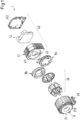
- Fig. 1 shows a perspective exploded view of a first embodiment of an electromagnetic rotary drive according to the invention, which is designated overall by the reference number 1.
- the electromagnetic rotary drive 1 comprises a motor unit 30, which is arranged in a motor housing 20, and a control unit 40 for controlling and supplying the motor unit 30 with electrical energy.
- the control unit 40 comprises a separate control housing 41, i.e. different from the motor housing 20, in which the various electronic or electrical components 42 of the control unit 40 are arranged.
- a thermal separating element 8a or 8b is provided between the control housing 41 and the motor housing 20, which on the one hand rests on the motor unit 30 and the motor housing 20, and on the other hand on the control unit 40.
- the thermal separating element 8a, 8b reduces or prevents a direct flow of heat from the motor unit 30 into the control unit 40 or vice versa from the control unit 40 into the motor unit 30.
- the thermal separating element 8a, 8b is designed such that the motor housing 20 and the control housing 41 do not have direct physical contact with each other, but are separated from each other by the thermal separating element 8a, 8b.
- the motor housing 20 and the control housing 41 are preferably made of a metallic material.
- a particularly suitable material for the motor housing 20 and the control housing 41 is aluminum, wherein in particular the outwardly exposed sides of the motor housing 20 and the control housing 41 can be designed with a coating, for example to improve the chemical resistance.
- the thermal separating element 8a is designed as an active cooling element through which a cooling fluid can flow.
- Fig. 4 shows a schematic sectional view of this first variant of the first embodiment with the thermal separating element 8a.
- the thermal separating element 8b is designed as a passive thermal separating element 8b, through which no cooling fluid flows.
- the separating element 8b thermally insulates the motor unit 30 from the control unit 40, so that at most a small heat flow is present from the control unit 40 to the motor unit 30 or vice versa from the motor unit 30 to the control unit 40.
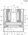
- the heat generated during operation is primarily released to the environment via convection, for example via the surface of the motor housing 20.
- Fig. 6 shows in a schematic sectional view this second variant of the first embodiment with the thermal separation element 8b.
- Fig. 1 The representation in Fig. 1 is to be understood that the thermal separating element 8a, 8b is either an active thermal separating element 8a (see Fig. 4 ) or as a passive thermal separator 8b ( Fig. 6 ) is designed.
- Fig. 1 thus illustrates the first and second variants of the first embodiment.
- the motor housing 20 has a recess 210 in one of its end faces, which is designed to accommodate a magnetically active core 31 ( Fig. 2 ) of a rotor 3.
- the recess 210 is in a separate rotor cup 21 (see also Fig. 4 ), the rotor cup 21 being designed as a cover of the motor housing 20, which closes the motor housing 20 at one of its axial ends as an axial end face.
- the rotor cup 21 is firmly connected to the motor housing 20, for example screwed or glued, or connected to the motor housing 20 by a press fit - with or without an O-ring.
- the rotor cup 21 closes the motor housing 20, preferably hermetically sealed.
- the separate rotor cup 21 is preferably made of a plastic, for example polypropylene.
- the electromagnetic rotary drive 1 is designed as a temple motor.
- the motor unit 30 comprises a stator 2.
- Fig. 2 another perspective Representation of the stator 2, where in Fig. 2 the motor housing 20 is not shown and a segment is cut out of the stator 2.
- the stator 2 has a plurality of coil cores 25 - here six coil cores 25 - each of which, according to the design as a temple motor, comprises a longitudinal leg 26 which extends in an axial direction A, as well as a transverse leg 27 arranged perpendicular to the longitudinal leg 26, which extends in a radial direction and is limited by an end face 211.
- the coil cores 25 are arranged equidistantly on a circular line, so that the end faces 211 surround the recess 210 into which the rotor 3 with the magnetically active core 31 can be inserted.
- On each longitudinal leg 26, exactly one concentrated winding 61 is provided, which surrounds the respective longitudinal leg 26.
- more than one concentrated winding 61 for example two concentrated windings each, can be provided on each longitudinal leg 26, each of which surrounds the respective longitudinal leg 26 and which are arranged adjacent to one another with respect to the axial direction A.
- the longitudinal legs 26 are each designed in a rod-shaped or essentially rod-shaped manner.
- the longitudinal legs 26 can also be designed as shown, for example, in the Fig. 3 or in the Fig. 5 the EP 4 084 304 A1 is shown.
- the rotor 3 can be magnetically supported without contact with respect to the stator 2. Furthermore, the rotor 3 can be magnetically driven without contact with respect to the stator 2 to rotate about a target axis of rotation.
- the target axis of rotation refers to the axis about which the rotor 3 rotates in the operating state when the rotor 3 is in a centered and non-tilted position with respect to the stator 2, as shown in Fig. 2 for the magnetically active core 31 of the rotor 3.
- This target axis of rotation defines the axial direction A.
- the target axis of rotation defining the axial direction A coincides with the center axis of the stator 2.
- a radial direction is defined as a direction that is perpendicular to the axial direction A.
- the number of six coil cores 25 is only to be understood as an example. Of course, embodiments are also possible in which the stator 2 has fewer than six, e.g. five, coil cores 25, or embodiments in which the stator 2 has more than six, e.g. seven or eight, coil cores 25.
- the rotor 3 comprises the magnetically active core 31, which is designed in the form of a ring or disk.
- the magnetically active core 31 is as shown in Fig. 2 designed as a ring and defines a magnetic center plane.
- the magnetically effective core 31 can also be designed as a disk.
- the magnetic center plane is the geometric center plane of the magnetically effective core 31 of the rotor 3, which is perpendicular to the axial direction A.
- the magnetically effective core 31 is mounted in a radial plane which is perpendicular to the axial direction A.
- the radial plane is the plane in which the magnetically active core 31 of the rotor 3 is actively magnetically supported between the end faces 211 in the stator 2 in the operating state. If the rotor 3 is not tilted and is not deflected in the axial direction A, the magnetic center plane lies in the radial plane.
- the radial plane defines the x-y plane of a Cartesian coordinate system whose z-axis runs in the axial direction A.
- the radial position of the magnetically active core 31 or the rotor 3 refers to the position of the rotor 3 in the radial plane.
- the rotor 3 can of course also comprise further components such as casings or encapsulations, which are preferably made of a plastic, or of a metal or a metal alloy or of a ceramic or a ceramic material. Furthermore, the rotor 3 can also comprise blades for mixing, stirring or pumping fluids or other components.
- the stator 2 is arranged in the motor housing 20 (see Fig. 1 ), which completely encloses the stator 2, so that the entire stator 2 is arranged inside the motor housing 20.
- Fig. 2 the motor housing 20 is not shown so that the components of the stator 2 arranged in the motor housing 20 can be seen.
- the motor housing 20 is particularly preferably designed as a hermetically sealed motor housing 20 which completely encapsulates the stator 2.
- the motor housing 20 is preferably filled with a thermally conductive casting compound, for example with an epoxy resin or with a polyurethane, so that the stator 2 and possibly other components arranged inside the motor housing 20 are surrounded by the casting compound. This reduces the general thermal resistance and dampens vibrations.
- the transverse legs 27 thus form a plurality of distinct stator poles - here six stator poles.
- the longitudinal legs 26 of the coil cores 25 each extend from a first end, which is the one shown ( Fig. 2 ) lower end, in the axial direction A to a second end, which is the upper end as shown.
- the transverse legs 27 are arranged at the upper ends of the longitudinal legs 26 and in the radial plane. Each transverse leg 27 extends in the radial direction towards the rotor 3.
- the magnetically active core 31 of the rotor 3 is in its desired position during operation, the magnetically active core 31 is centered between the end faces 211 of the transverse legs 27, so that the transverse legs 27 arranged in the radial plane are also in the magnetic center plane.
- the concentrated windings 61 are arranged below the radial plane as shown and are aligned so that their coil axes each run in the axial direction A.
- the return line 22 is preferably designed in a ring shape. Designs are possible in which the return line 22 extends radially inward along all the first ends of the longitudinal legs 26. However, it is also possible for the return line 22 to have several recesses along its circumference, each of which accommodates one of the first ends. In other embodiments, the return line 22 can also comprise a plurality of ring segments, each of which is arranged between two coil cores 25 adjacent in the circumferential direction in the region of the first ends.
- the longitudinal legs 26 of the coil cores 25 carry the windings 61 designed as concentrated windings 61, with exactly one concentrated winding 61 being arranged around each longitudinal leg 26 in the first embodiment.
- these concentrated windings 61 generate those electromagnetic rotating fields with which a torque is caused on the rotor 3 and with which an arbitrarily adjustable transverse force can be exerted on the rotor 3 in the radial direction, so that the radial position of the rotor 3, i.e. its position in the radial plane perpendicular to the axial direction A, can be actively controlled or regulated.
- the "magnetically active core 31" of the rotor 3 refers to that region of the rotor 3 which magnetically interacts with the stator 2 for the generation of torque and for the generation of the magnetic bearing forces.
- the magnetically active core 31 is designed in a ring shape in this embodiment. Furthermore, the magnetically active core 31 is designed to be permanent magnetic.
- the magnetically active core 31 can comprise at least one permanent magnet, but also several permanent magnets or - as in the case of the described first embodiment - consist entirely of a permanent magnetic material, so that the magnetically active core 31 is the permanent magnet.
- the magnetically active core 31 is magnetized, for example, in the radial direction.
- Permanent magnets are usually ferromagnetic or ferrimagnetic materials that are hard magnetic, i.e. have a high coercive field strength.
- the coercive field strength is the magnetic field strength that is required to demagnetize a material.
- a permanent magnet is understood to be a material that has a coercive field strength, or more precisely a coercive field strength of the magnetic polarization, that is more than 10,000 A/m.
- the magnetically active core 31 is designed without permanent magnets, i.e. without permanent magnets.
- the rotor 3 is then designed as a reluctance rotor, for example.
- the magnetically active core 31 of the rotor 3 then consists of a soft magnetic material, for example.
- Suitable soft magnetic materials for the magnetically active core 31 are, for example, ferromagnetic or ferrimagnetic materials, i.e. in particular iron, nickel-iron, cobalt-iron, silicon-iron, mu-metal.
- the magnetically active core 31 of the rotor 3 comprises both ferromagnetic materials and permanent magnetic materials.
- permanent magnets can be inserted or inserted into a ferromagnetic base body. Such designs are advantageous, for example, if one wants to reduce costs for large rotors by saving on permanent magnetic material.
- Both the ring-shaped return path 22 and the coil cores 25 of the stator 2 are each made of a soft magnetic material because they serve as flux guiding elements for guiding the magnetic flux.
- Suitable soft magnetic materials for the coil cores 25 and the return path 22 are, for example, ferromagnetic or ferrimagnetic materials, i.e. in particular iron, nickel-iron, cobalt-iron, silicon-iron or mu-metal.
- ferromagnetic or ferrimagnetic materials i.e. in particular iron, nickel-iron, cobalt-iron, silicon-iron or mu-metal.
- a design as a stator laminated core is preferred for the stator 2, in which the coil cores 25 and the return path 22 are laminated, i.e. they consist of several thin sheet metal elements that are stacked.
- the coil cores 25 and the return path 22 may consist of pressed and then sintered grains of the materials mentioned.
- the metallic grains are preferably embedded in a plastic matrix so that they are at least partially electrically insulated from one another, which minimizes eddy current losses.
- Soft magnetic composite materials which consist of electrically insulated and pressed metal particles, are therefore also suitable for the stator.
- these soft magnetic composite materials which are also referred to as SMC (Soft Magnetic Composites) can consist of iron powder particles that are coated with an electrically insulating layer. These SMCs are then formed into the desired configuration using powder metallurgy processes.
- the magnetically active core 31 of the rotor 3 interacts with the stator 2 according to the principle of the bearingless motor described at the beginning, in which the rotor 3 can be magnetically driven without contact and can be magnetically supported without contact with respect to the stator 2.
- the stator 2 is designed as a bearing and drive stator, with which the rotor 3 can be magnetically driven without contact around the desired axis of rotation in the operating state - i.e. can be set in rotation - and can be magnetically supported without contact with respect to the stator 2.
- Three degrees of freedom of the rotor 3 namely its position in the radial plane and its rotation, can be actively controlled.
- the magnetically active core 31 of the rotor 3 is passively magnetic, i.e. cannot be controlled, and is stabilized by reluctance forces.
- the magnetically active core 31 of the rotor 3 is also passively magnetically stabilized with respect to the remaining two degrees of freedom, namely tilting with respect to the radial plane perpendicular to the target axis of rotation.
- the rotor 3 is therefore passively magnetically supported in the axial direction A and against tilting (a total of three degrees of freedom) by the interaction of the magnetically active core 31 with the coil cores 25, or is passively magnetically stabilized and actively magnetically supported in the radial plane (two degrees of freedom).
- an active magnetic bearing also refers to one that can be actively controlled or regulated, for example via the electromagnetic rotating fields generated with the concentrated windings 61.
- a passive magnetic bearing or a passive magnetic stabilization refers to one that cannot be controlled or regulated.
- the passive magnetic bearing or stabilization is based, for example, on reluctance forces, which bring the rotor 3 back to its target position when it is deflected from its target position, for example when it is shifted or deflected in the axial direction A or when it is tilted.
- a radial bearing or a radial bearing is a bearing of the rotor 3 with which the radial position of the rotor 3 can be stabilized, i.e. a Bearing which supports the rotor 3 in the radial plane and thus with respect to its radial position.
- An axial bearing or an axial bearing or an axial stabilization or an axial stabilization refers to a bearing or a stabilization of the rotor 3 with which, on the one hand, the position of the rotor 3 is stabilized with respect to the axial direction A, and with which, on the other hand, the rotor 3 is stabilized against tilting.
- Such tilting represents two degrees of freedom and refers to deflections in which the current axis of rotation of the rotor 3 no longer points exactly in the axial direction A, but rather encloses an angle other than zero with the desired axis of rotation.
- the magnetic center plane is no longer in or parallel to the radial plane, but rather the magnetic center plane encloses an angle other than zero with the radial plane.
- the magnetic bearing and the drive of the motor are realized via electromagnetic rotating fields.
- the magnetic drive and bearing function is generated by the superposition of two magnetic rotating fields, which are usually referred to as the drive and control fields.
- These two rotating fields generated with the windings of the stator usually have a number of pole pairs that differs by one. For example, if the drive field has the number of pole pairs p, the control field has the number of pole pairs p+1 or p-1.
- the drive field generates tangential forces acting on the magnetically active core 31 in the radial plane, which cause a torque, which causes rotation around the axial direction A.
- an arbitrarily adjustable transverse force can also be generated on the magnetically active core 31 in the radial plane, with which the position of the magnetically active core 31 in the radial plane can be regulated. It is therefore not possible to divide the electromagnetic flux generated by the concentrated windings 61 into an (electro-)magnetic flux that only drives the rotation and an (electro-)magnetic flux that only realizes the magnetic bearing.
- the coils for generating the drive field are then usually referred to as drive coils and the coils for generating the control field are referred to as control coils.
- two concentrated windings can be provided on each coil core 25, which are arranged adjacent to each other with respect to the axial direction A.
- One of the windings is used as a drive coil, while the other concentrated winding adjacent to it is used as a control coil.
- the current flowing into this Coils is then referred to as the drive current or control current.
- the drive field which is an electromagnetic rotating field, is then generated with the totality of all drive coils, while the control field, which is also an electromagnetic rotating field, is generated with the totality of the control coils and is superimposed on the drive field.
- the superimposition of the drive field and the control field then enables the tangential forces on the rotor 3 to be generated, which generate the torque to drive the rotation, as well as an arbitrarily adjustable transverse force in the radial plane, with which the position of the magnetically active core 31 in the radial plane can be actively controlled.
- a circuit board 71 ( Fig. 2 ) with electronic components not shown in detail.
- the circuit board 71 is preferably designed as an electronic print or PCB (printed circuit board).
- Components that are used for controlling sensors (not shown) and/or for evaluating the measurement signals determined by sensors can be provided on the circuit board 71.
- sensors include, for example, position sensors for determining the current position of the rotor 3.
- the circuit board 71 and the electronic components provided thereon are signal-connected to the control unit 40.
- the circuit board 71 is essentially ring-shaped and arranged parallel to the radial plane.
- the ring-shaped circuit board 71 is arranged radially inwardly with respect to the coil cores 25, wherein the circuit board 71 - as in Fig. 2 can be seen - can also extend into the spaces between the longitudinal legs 26 of adjacent coil cores 25.
- the circuit board 71 is arranged between the windings 61 and the transverse legs 27 of the coil cores 25. According to the illustration in Fig. 2 is the The circuit board 71 is thus arranged below and adjacent to the transverse legs 27, which are arranged around the magnetically active core 31 of the rotor 3.
- the control unit 40 comprises the electrical or electronic components 42 which are necessary for controlling and supplying the windings 61 with electrical energy. These are in particular rectifiers or converters with which the voltage or current is provided for supplying the windings 61, circuit breakers 420 ( Fig. 4 ) for the rectifiers, filter components 421, e.g. capacitors or inductors for smoothing the direct current, power switches 422 for controlling the windings 61, with which the current supplied to the windings 61 is switched, regulating and control components for controlling the contactless magnetic bearing and the contactless magnetic drive, evaluation components for sensor signals.
- the rectifier for providing the supply voltage for the windings 61 is preferably designed with a power factor correction filter (PFC: Power Factor Correction or Power Factor Compensation) in order to reduce the distortion reactive power and thus increase the power factor of the rectifier.
- PFC Power Factor Correction or Power Factor Compensation
- the stator 2 further comprises a thermal conducting element 9 for dissipating the heat that is generated during operation in the windings 61, the coil cores 25 and the return path 22.
- This heat is based in particular on the copper losses in the windings 61 and the iron losses in the coil cores 25 and the return path 22.
- the thermal conducting element 9 serves to dissipate the heat generated in the windings 61, the coil cores 25 and the return path 22 as well as possible.
- Fig. 3 another perspective view of the thermal conducting element 9.
- the thermal conducting element 9 comprises a thermal conducting plate 91, which is arranged between the coil cores 25 and the thermal separating element 8a, 8b with respect to the axial direction A.
- the thermal conducting plate 91 is in very good thermal contact, preferably in physical contact, on the one hand with the thermal separating element 8a, 8b and on the other hand with the coil cores 25 or with the return path 22.
- the thermal conducting plate 91 is preferably in physical contact with the first - lower as shown - ends of all the coil cores 25 and with the return path 22.
- the thermal conducting plate 91 particularly preferably rests against the return path 22 over the entire circumference in order to be able to absorb heat from it as well as possible.
- thermally conductive paste for example a thermal paste, between the thermal conduction plate 91 and the coil cores 25 or the return path 22, which thermally couples the adjacent components particularly well with one another.
- the thermal conducting element 9 further comprises a plurality - here six - of conducting teeth 92, each of which is connected to the thermal conducting plate 91.
- Each conducting tooth 92 extends from the thermal conducting plate 91 in the axial direction A and is arranged radially inwardly with respect to the windings 61 in the interior space surrounded by the windings 61, as can be seen in particular in Fig. 2 can be seen.
- the number of guide teeth 92 is equal to the number of coil cores 25 and exactly one guide tooth 92 is arranged in front of each coil core 25.
- the guide teeth 92 are arranged as close as possible to the longitudinal legs 26 of the coil cores 25 or the windings 61 arranged thereon, so that the guide teeth 92 can absorb and dissipate the heat generated by the windings 61 and the coil cores 25 particularly well.
- the thermal conducting element 9 is designed in one piece in order to minimize thermal resistance in the thermal conducting element 9.
- the thermal conducting element consists of a material that conducts heat well, for example a metallic material.
- a preferred material for the thermal conducting element 9 is aluminum.
- a further preferred measure consists in providing a recess 93 between each two adjacent guide teeth 9 in the circumferential direction, which extends in the axial direction A into the area of the first ends of the longitudinal legs 26 or up to the thermal conduction plate 91. Eddy currents or eddy current losses are minimized by these recesses 93. Such eddy currents could be induced in the thermal conduction element 9 by the stray fields of the current flowing in the windings 61. The recesses 93 lead to a significant reduction in eddy current losses in the thermal conduction element 9.
- each guide tooth 92 is located exactly opposite one longitudinal leg 26 and each recess 93 is arranged between two adjacent coil cores 25.
- Fig. 4 shows this first variant of the first embodiment in a schematic sectional view in a section in axial direction A.
- the motor housing 20 and the different control housing 41 of the control unit 40 do not have direct physical contact with each other, but are separated from each other by the thermal separating element 8a, which is arranged between the motor housing 20 and the control housing 41 with respect to the axial direction A.
- the thermal separating element 8a is located on the motor housing 20, thus is in physical contact with the motor housing 20.
- the thermal separating element 8a rests on the control housing 41, thus is in physical contact with the control housing 41.
- Fig. 5 a sectional view of the thermal separating element 8a of the first variant in a section perpendicular to the axial direction A.
- the thermal separating element 8a is designed in the form of a plate and has essentially the shape of a circular disk.
- At least one passage 85 is provided in the thermal separating element 8a, which extends completely through the thermal separating element 8a in the axial direction.
- the passages 85 serve to enable signal connections from the control unit 40 to be led through the thermal separating element 8a into the motor unit 30, for example electrical lines for supplying the windings 61 with electrical energy.
- the separating element 8a is preferably made of a metallic material, for example steel or stainless steel. Furthermore, the outer surfaces of the thermal separating element 8a, i.e. those surfaces that are in contact with the environment, can be provided with a coating (not shown).
- both the thermal conduction plate 91 of the thermal conduction element 9 and the motor housing 20 rest on the thermal isolating element 8a in order to ensure the best possible thermal connection of the thermal isolating element 8a to the return path 22, the windings 61, the coil cores 25 and the motor housing 20.
- This makes it possible for the heat generated in the stator 2 during operation, which is primarily due to the iron losses and the copper losses, to be efficiently and reliably dissipated into the thermal isolating element 8a.
- the thermal separating element 8a rests against the control housing 41 of the control unit 40 in order to ensure very good thermal contact between the control unit 40 and the thermal separating element 8a.
- the control housing 41 has several openings 43 (see Fig. 1 ), through which signal connections (not shown) can be led from the control unit 40 through the passages 85 of the thermal isolation element 8a into the motor unit 30, for example electrical lines for supplying the windings 61 with electrical energy.
- the control housing 41 further comprises a control housing cover 412, which closes the control housing 41 on its axial end face facing away from the thermal separating element 8a, preferably hermetically.
- the control housing cover 412 is preferably made of a metallic material, for example aluminum.
- the control housing cover 412 is designed with one or more passages (not shown), through which a supply cable for feeding in electrical energy or an interface cable for controlling the electromagnetic rotary drive 1 and/or for data exchange can be led from the outside into the control housing 41.
- the control unit 40 comprises at least one, preferably several circuit boards 44, 45 on which the electronic components 42 of the control unit 40 are arranged.
- Each circuit board 44, 45 is preferably designed as an electronic print or PCB (printed circuit board).
- the control unit 40 comprises a controller board 44 and a supply board 45, which are arranged parallel to one another and offset from one another with respect to the axial direction A.
- the supply board 45 includes all the electronic components 42 that provide a direct voltage, with which in particular the windings 61 can be supplied with electrical energy. Since the electromagnetic rotary drive 1 is typically connected to an external alternating current source (not shown), for example to a technical three-phase current source or to a conventional single-phase alternating current source with an alternating voltage of 200-240 volts, a rectifier or converter is provided on the supply board 45, which converts the alternating voltage into a direct voltage, which is then used, for example, as an intermediate circuit voltage for controlling the windings 61.
- the converter includes power switches 420 for rectification and the PFC circuit.
- filter components 421 are provided on the supply board 45, e.g. capacitors or inductors for smoothing the direct current.
- the controller board 44 contains the electronic components required to control the windings 61 to implement the drive and bearing functions. These are in particular the power switches 422 for controlling the windings 61. The intermediate circuit voltage required for the power switches 422 is provided by the supply board 45. The controller board 44 also contains regulation and control components for controlling the contactless magnetic bearing and the contactless magnetic drive, as well as optional evaluation components for sensor signals (not shown).
- the power switches 420, 422 are preferably made of silicon carbide.
- the circuit boards are - as in Fig.4 shown - arranged directly on the control housing 41, so that the circuit boards 44, 45 are in physical contact with the control housing 41.
- the circuit breakers 420, 422 as the main heat sources are arranged in the areas of the circuit boards 44, 45 that are in contact with the control housing 41.
- the areas of the circuit boards that are in contact with the control housing 41 44, 45 may be designed with a copper surface and/or with a thermal pad in order to achieve an even better thermal coupling.
- the thermal connections between the individual components as well as the thermal connection to the thermal separating element 8a can be further improved depending on the design by providing a thermally conductive paste, for example a thermal paste, between adjacent components.
- the thermal separating element 8a When the thermal separating element 8a is designed as an active cooling element, at least one cooling line 81 ( Fig. 5 ) through which a cooling fluid can flow, which removes heat from the thermal separating element 8a.
- the cooling line 81 extends as a continuous line from a first cooling connection 811 through the interior of the thermal separating element 8a to a second cooling connection 812, through which the cooling fluid can be introduced into the cooling line 81 or removed from the cooling line 81.
- the cooling connections 811, 812 are each provided on the outer circumferential surface of the thermal separating element 8a, so that the cooling fluid can be fed into the cooling line 81 from outside the separating element 8a by means of the first cooling connection 811, for example, and can be removed from the separating element 8a again by means of the second cooling connection 812.
- the cooling line 81 is designed in such a way that it passes through as many areas of the thermal separating element 8a as possible in order to dissipate a large amount of heat as efficiently as possible.
- Fig. 5 The embodiment of the cooling line 81 shown as an example comprises a plurality of straight bores 813 which are laid out and designed in such a way that they complement each other to form the continuous cooling line 81 which connects the two cooling connections 811, 812 to one another.
- Each of the bores 813 is drilled from the outer circumferential surface of the thermal separating element 8a into the interior of the thermal separating element 8a.
- the cooling fluid is preferably a liquid, for example water.
- a particularly preferred cooling fluid is demineralized or deionized water (DI water). DI water is a typical cooling fluid that is often used, for example, in production plants in the semiconductor industry.
- the thermal separating element 8a is preferably made of steel, stainless steel or rust-proof steel. Such steel also has the advantage that it is more corrosion-resistant than, for example, copper. In particular, when using If water is used as a cooling fluid, which is more aggressive than, for example, normal water, it is advantageous to manufacture the thermal separating element 8a from a stainless steel or from a stainless steel.
- the outwardly exposed surfaces of the thermal separating element 8a can be coated, in particular for applications that require increased chemical resistance, for example with an epoxy resin (epoxy), polytetrafluoroethylene (PTFE), ethylene-tetrafluoroethylene (ETFE) or another plastic.
- epoxy resin epoxy
- PTFE polytetrafluoroethylene
- ETFE ethylene-tetrafluoroethylene
- Fig. 6 shows this second variant of the first embodiment in a schematic sectional view in a section in axial direction A.
- the thermal separating element 8b is essentially ring-shaped (see also Fig. 1 ) and forms a thermal insulation between the motor unit 30 and the control unit 40.
- the thermal separating element 8b is arranged between the motor housing 20 and the control housing 41 with respect to the axial direction A in such a way that it prevents direct contact between the motor housing 20 and the control housing 41.
- the motor housing 20 rests against the thermal separating element 8b
- the control housing 41 rests against the thermal separating element 8b.
- the outer diameter of the thermal separating element 8b is at most as large as the outer diameter of the motor housing 20 or the outer diameter of the control housing 41, whereby it is also preferred that the outer diameter of the motor housing 20 is at least substantially the same size as the outer diameter of the control housing 41.
- FIG. 6 shows an embodiment in which the outer diameters of the motor housing 20, the thermal separating element 8b and the control housing 41 are all essentially the same size.
- the outer diameter of the thermal separating element 8b is smaller than the outer diameter of the control housing 41 or the motor housing 20.
- Fig. 1 illustrated.
- a substantially circular housing recess 411 is provided which accommodates the thermal separating element 8b.
- a substantially identical housing recess is arranged, which, however, is in Fig. 1 cannot be seen.
- the depths of the housing recess 411 and the housing recess in the motor housing 20, which means their respective extension in the axial direction A, are dimensioned such that the motor housing 20 and the control housing 41 do not touch in the assembled state, but are separated from one another by an air gap.
- the thermal separating element 8b of the second variant which is designed as a passive separating element for thermal decoupling of the motor unit 30 from the control unit 40, is preferably made of a plastic.
- a chemically resistant plastic such as polypropylene is preferred, particularly for applications in chemically aggressive environments.
- Fig. 7 shows a perspective exploded view of a second embodiment of an electromagnetic rotary drive 1 according to the invention.
- Fig. 8 another schematic sectional view of the second embodiment in a section along the axial direction A.
- control unit 40 is arranged in the motor housing 20, i.e. no separate control housing 41 is provided, but the control unit 40 is located in the motor housing 20.
- the thermal separating element 8a, 8b can be designed as an active cooling element 8a, which has at least one internal cooling line 81 through which a cooling fluid, for example water, in particular DI water, can flow, or as a passive separating element 8b between the motor unit 30 and the control unit 40, i.e. without internal cooling lines.
- a cooling fluid for example water, in particular DI water
- Fig. 7 and Fig. 8 show an embodiment in which the thermal separating element 8a is designed as an active cooling element.
- Fig. 9 in a Fig. 5 analogous representation of this thermal separating element 8a in a sectional view in a section perpendicular to the axial direction A.
- Fig. 10 shows in a schematic sectional view a variant of the second embodiment, in which the thermal separating element 8b is designed as a passive thermal separating element between the motor unit 30 and the control unit 40.
- thermal separation element 8a is designed as an active cooling element.
- the motor housing 20 is closed by a housing cover 23.
- the housing cover 23 is preferably made of a plastic.
- a chemically resistant plastic such as polypropylene is preferred, particularly for applications in chemically aggressive environments.
- the motor housing 20 is also preferably designed to be hermetically sealed.
- the motor housing 20 is connected to the rotor cup 21 and the housing cover 23 at both of its axial ends in a hermetically sealed manner, for example by screwing. Seals, in particular flat seals, can be provided between the motor housing 20 and the rotor cup 21 or the housing cover 23.
- the motor housing 20 (see in particular Fig. 8 ) an inner cup 201 which is essentially cylindrical and which is arranged radially inward with respect to the windings 61 in the interior space surrounded by the windings 61.
- the inner cup 201 is connected to the outer wall 203 of the motor housing 20 via a flange-like projection 202.
- the outer wall 203 forms the radially outer boundary of the motor housing 20.
- the inner cup 201 and the flange-like projection 202 are particularly preferably an integral part of the motor housing 20.
- the outer wall 203, the flange-like projection 202 and the inner cup 201 are designed as a single piece in their entirety and form the preferably single-piece motor housing 20.
- the thermal conducting element 9 is not provided in the second embodiment. Instead, the inner cup 201 and the flange-like projection 202 are provided in the second embodiment in order to absorb the heat generated by the windings 61, the coil cores 25 and the return path 22. This heat is then dissipated with the aid of the thermal separating element 8a, which is designed as an active cooling element, with part of this heat also being dissipated by means of convection, in particular via the outer wall 203 of the motor housing 20.
- the flange-like projection 202 which connects the outer wall 203 of the motor housing 20 to the inner cup 201, is arranged with respect to the axial direction A between the coil cores 25 and the thermal separating element 8a.
- the flange-like projection 202 is in very good thermal contact, preferably in physical contact, on the one hand with the thermal separating element 8a and on the other hand with the coil cores 25 or with the return 22.
- the flange-like projection 202 is connected to the first, as shown ( Fig. 8 ) lower ends of all coil cores 25 in physical contact and with the return path 22.
- the flange-like projection 202 rests against the return path 22 over the entire circumference in order to be able to absorb heat from it as well as possible.
- a thermally conductive paste for example a thermal paste, between the flange-like projection 202 and the coil cores 25 or the return path 22, which thermally couples the adjacent components particularly well with one another.
- the inner cup 201 connected to the flange-like projection 202 extends from the radially inner edge of the flange-like projection 202 in the axial direction A and is arranged radially inward with respect to the windings 61 in the interior space surrounded by the windings 61, as is particularly shown in Fig. 8 can be seen.
- the inner cup 201 is arranged as close as possible to the longitudinal legs 26 of the coil cores 25 or the windings 61 arranged thereon, so that the inner cup 201 can absorb and dissipate the heat generated by the windings 61 and the coil cores 25 particularly well.
- the inner cup 201 extends approximately to the illustrated ( Fig. 8 ) upper end of the windings 61.
- the inner cup 201 extends over the entire length of the windings 61 with respect to the axial direction A.
- the one-piece motor housing 20 which comprises the inner cup 201, the flange-like projection 202 and the outer wall 203, is provided.
- the stator 2 with the windings 61 arranged on the coil cores 25 and the circuit board 71 is inserted into the motor housing 20.
- the motor housing 20 can then be filled with the thermal casting compound and finally sealed with the rotor cup 21.
- the thermal separating element 8a is dimensioned such that it can be inserted into the motor housing 20.
- the thermal separating element 8a rests on the flange-like projection 202 of the motor housing 20 over as large an area as possible, i.e. it is in physical contact with the motor housing 20. This ensures the best possible thermal contact between the flange-like projection 202 and the thermal separating element 8a, so that very good heat transfer from the flange-like projection 202 or the inner cup 201 into the thermal separating element 8a is possible.
- Fig. 9 a sectional view of the thermal separating element 8a of the second embodiment in a section perpendicular to the axial Direction A.
- the thermal separating element 8a is designed in the form of a plate and has essentially a rectangular or square shape.
- At least one passage 85 is provided in the thermal separating element 8a in order to guide signal connections from the control unit 40 through the thermal separating element 8a into the motor unit 30, for example electrical lines for supplying the windings 61 with electrical energy.
- the thermal isolating element 8a rests against the flange-like projection 202 of the motor housing 20 in order to ensure the best possible thermal connection of the thermal isolating element 8a to the return path 22, the windings 61, the coil cores 25 and the motor housing 20.
- This makes it possible for the heat generated in the stator 2 during operation, which is primarily due to the iron losses and the copper losses, to be efficiently and reliably dissipated into the thermal isolating element 8a.
- the controller board 44 of the control unit 40 is arranged on the side of the thermal separating element 8a facing away from the motor unit 30 and is arranged directly on the thermal separating element 8a in order to ensure very good thermal contact between the control unit 40 and the thermal separating element 8a. This allows the heat generated in the control unit 40 to be efficiently dissipated into the thermal separating element 8a.
- the thermal separating element 8a which is designed as an active cooling element, comprises at least one cooling line 81 through which the cooling fluid can flow, which removes heat from the thermal separating element 8a.
- the cooling line 81 extends as a continuous line from the first cooling connection 811 through the interior of the thermal separating element 8a to the second cooling connection 812, through which the cooling fluid can be introduced into the cooling line 81 or removed from the cooling line 81.
- the cooling connections 811, 812 each extend in the axial direction A through the housing cover 23 (see Fig. 8 ), so that the cooling fluid can be fed into the cooling line 81 from outside the motor housing 20 by means of, for example, the first cooling connection 811 and can be discharged from the motor housing 20 again by means of the second cooling connection 812.
- the cooling line 81 is designed in such a way that it can dissipate a large amount of heat as efficiently as possible.
- Fig. 9 The embodiment of the cooling line 81 shown as an example comprises several straight holes 813 which are designed and constructed in such a way that they complement each other to form the continuous cooling line 81 which connects the two cooling connections 811, 812. Each of the holes 813 is drilled from the outside of the thermal separating element 8a into the interior of the thermal separating element 8a.
- the controller board 44 is again provided in the control unit 40.
- the controller board 44 contains those electronic components which are required for controlling the windings 61 to implement the drive and bearing functions. These are in particular the power switches 422 for controlling the windings 61.
- the controller board 44 also contains regulation and control components for controlling the contactless magnetic bearing and the contactless magnetic drive, as well as optional evaluation components for sensor signals.
- a rectifier integrated into the control unit 40 when designing the rotary drive 1 for lower powers of, for example, a maximum of 600 watts, it is possible to dispense with a rectifier integrated into the control unit 40. Accordingly, in the design according to Fig. 8 no supply board 45 is provided. A direct voltage of, for example, 24 volts or 48 volts is then provided as the supply voltage from an external source (not shown). For this purpose, a feedthrough 403 ( Fig. 8 ) is provided, through which the electrical energy in the form of direct current can be fed into the control unit 40 from a supply cable. The direct current serves to provide the intermediate circuit voltage required for the power switches 422 on the controller board 44.
- the power switches 422 are MOSFETs.
- the controller board 44 is arranged directly on the thermal isolating element 8a so that the controller board 44 is in physical contact with the thermal isolating element 8a.
- the power switches 422 as the main heat sources in the control unit 40 are thus arranged as close as possible to the thermal isolating element 8a.
- the areas of the controller board 44 adjacent to the thermal isolating element 8a can be designed with a copper surface and/or with a thermal pad in order to achieve even better thermal coupling.
- control unit 40 is designed in the same way as for the first embodiment described may include an internal rectifier for providing the supply voltage. This can then be arranged on a supply board 45, in a manner analogous to that described in Fig. 4 or in Fig. 6 presented and based on this Fig. 4 , Fig. 6 described.
- the thermal separating element 8b is designed as a passive thermal separating element 8b between the motor unit 30 and the control unit 40, ie as such a thermal separating element 8b through which no cooling fluid flows, but releases the absorbed heat to the environment mainly via convection.
- the thermal separating element 8b comprises the inner cup 201 and the flange-like projection 202, which are preferably an integral part of the motor housing 20.
- the inner cup 201, the flange-like projection 202 and the outer wall 203 are preferably designed as a single piece, which enables a particularly simple and cost-effective manufacture of the motor housing 20.
- the thermal separating element 8b is thus an integral part of the motor housing 20.
- the thermal separating element 8b absorbs both the heat generated in the motor unit 30 and the heat generated in the control unit 40, which is then released to the environment primarily by means of convection via the outer wall 203 of the motor housing 20.
- the controller board 44 is arranged directly on the flange-like projection 202, so that the controller board 44 rests on the thermal isolating element 8b.
- the power switches 422 as the main heat sources in the control unit 40 are preferably arranged in the areas of the controller board 44 that rest on the thermal isolating element 8b.
- the invention further proposes a centrifugal pump 100 for conveying a fluid, which is characterized in that the centrifugal pump 100 comprises an electromagnetic rotary drive 1, which is designed according to the invention, and a rotor 3, which can be driven to rotate with the electromagnetic rotary drive 1.
- the rotor 3 comprises a magnetically active core 31, which is arranged in the recess 210 in the motor housing 20.
- the rotor 3 is designed as rotor 3 of the centrifugal pump 100.
- Fig. 11 shows an embodiment of a centrifugal pump according to the invention, which is designated overall by the reference numeral 100, in a perspective view.
- Fig. 12 a schematic sectional view of the embodiment from Fig. 11 in a section in axial direction A.
- the motor housing 20, the control unit 40 and the thermal separation element 8a, 8b are not shown.
- the centrifugal pump 100 comprises a pump unit 50 with a pump housing 51, which comprises an inlet 52 and an outlet 53 for the fluid to be conveyed, wherein the rotor 3 is arranged in the pump housing 51, and comprises a plurality of vanes 54 for conveying the fluid.
- the pump unit 50 is designed such that the pump unit 50 can be inserted into the recess 210 such that the magnetically active core 31 of the rotor 3 is surrounded by the end faces 211 of the transverse legs 27.
- the pump unit 50 is shown separated from the stator 2.
- the electromagnetic rotary drive 1 is designed according to the first embodiment, i.e. it has the motor housing 20 and the control housing 41 separate therefrom, wherein the thermal separating element 8a or 8b is arranged between the motor housing 20 and the control housing 41, which can be designed as an active cooling element 8a or as a passive thermal separating element 8b.
- the pump unit 50 is inserted into the recess 210 (in Fig. 12 not shown) and thus inserted into the stator 2. Furthermore, Fig. 12
- the dashed line with the reference symbol E indicates the radial plane in which the magnetically active core 31 of the rotor 3 is magnetically mounted without contact.
- the rotor 3 is designed as an integral rotor because it is both the rotor 3 for the electromagnetic rotary drive 1 and the rotor 3 of the centrifugal pump 100, with which the fluid is conveyed.
- the rotor 3 thus fulfills three functions in one: It is the rotor 3 for the electromagnetic rotary drive 1, it is the rotor 3 of the magnetic bearing, and it is the impeller with which the fluid or fluids are acted upon.
- This design as an integral rotor offers the advantage of a very compact and space-saving design.
- the stator 2 is arranged in the motor housing 20, which is preferably designed as a hermetically sealed motor housing 20 and encapsulates the stator 2.
- the circuit board 71 is also arranged in the motor housing 20.
- the stator housing 20 is preferably filled with a potting compound, for example with an epoxy resin or with a polyurethane. so that the stator 2 and possibly other components arranged inside the motor housing 20 are surrounded by the potting compound.
- the motor housing 20 also has the recess 210 in the rotor cup 21 at its end facing the pump unit 50, so that the pump unit 50 can be inserted into this recess 210.
- the rotor 3 provided in the pump housing 51 is then enclosed by this recess 210 in the motor housing 20, wherein the magnetically active core 31 of the rotor 3 is arranged between the transverse legs 27 of the coil cores 25.
- the pump housing 51 is fixed to the stator housing 20, preferably with a plurality of screws 511.
- the control unit 40 comprises the control housing 41, in which the various electronic or electrical components 42 of the control unit 40, in particular also the controller board 44 and the supply board 45, are arranged.
- the control housing 41 is preferably designed as a hermetically sealed control housing 41, which encapsulates the electronic components 42.
- the control housing 41 is preferably filled with a potting compound, for example with an epoxy resin or with a polyurethane, so that the boards 44, 45 and possibly other components that are arranged inside the control housing 41 are surrounded by the potting compound.
- a supply cable 401 for feeding electrical energy into the control unit 40 is shown, as well as an interface cable 402 for controlling the electromagnetic rotary drive 1 and/or for data exchange.
- the interface cable 402 is used, for example, to transmit signals for controlling a programmable logic controller (PLC) to the control unit 40.
- PLC programmable logic controller
- the supply cable 401 and the interface cable 402 are connected to the interior of the control housing 41 via bushings (not shown in detail).
- the rotor 3 comprises the plurality of vanes 54 for conveying the fluid. In the embodiment described here, for example, a total of four vanes 54 are provided, this number being exemplary in nature.
- the rotor 3 further comprises a casing 38 with which the magnetically active core 31 of the rotor 3 is enclosed and preferably hermetically encapsulated, so that the magnetically active core 31 of the rotor 3 does not come into contact with the fluid to be conveyed. All vanes 54 are arranged on the casing 38 and are arranged equidistantly with respect to the circumferential direction of the rotor 3. Each vane 54 extends radially outwards and is connected to the casing 38 in a rotationally fixed manner.
- the vanes 54 can be separate components which are then fixed to the casing 38. It is of course also possible It is possible that all vanes 54 are an integral part of the casing 38, i.e. that the casing 38 is designed as one piece with all vanes 54.
- the rotor 3 with the vanes 54 forms the impeller or the rotor of the centrifugal pump 100, with which the fluid or fluids are acted upon.
- the pump housing 51 of the pump unit 50 as well as the casing 38 and the vanes 54 are made of one or more plastics.
- Suitable plastics are: polyethylene (PE), low density polyethylene (LDPE), ultra low density polyethylene (ULDPE), ethylene vinyl acetate (EVA), polyethylene terephthalate (PET), polyvinyl chloride (PVC), polypropylene (PP), polyurethane (PU), polyvinylidene fluoride (PVDF), acrylonitrile butadiene styrene (ABS), polyacrylic, polycarbonate (PC), polyetheretherketone (PEEK) or silicone.
- the materials polytetrafluoroethylene (PTFE) and perfluoroalkoxy polymers (PFA), known under the brand name Teflon are also suitable as plastics.
- the electromagnetic rotary drive according to the invention is also suitable for devices other than centrifugal pumps, for example for mixing devices for mixing flowable substances, for stirring devices, for example for mixing a fluid in a tank, for fans or also for devices for carrying and rotating wafers, for example in semiconductor production.
Landscapes
- Engineering & Computer Science (AREA)
- Power Engineering (AREA)
- Mechanical Engineering (AREA)
- General Engineering & Computer Science (AREA)
- Microelectronics & Electronic Packaging (AREA)
- Physics & Mathematics (AREA)
- Thermal Sciences (AREA)
- Electromagnetism (AREA)
- Chemical & Material Sciences (AREA)
- Combustion & Propulsion (AREA)
- Connection Of Motors, Electrical Generators, Mechanical Devices, And The Like (AREA)
- Structures Of Non-Positive Displacement Pumps (AREA)
Abstract
Es wird ein elektromagnetischer Drehantrieb vorgeschlagen, der als Tempelmotor ausgestaltet ist, und eine Motoreinheit (30) sowie eine Kontrolleinheit (40) umfasst, wobei die Motoreinheit (30) in einem Motorgehäuse (20) angeordnet ist, welches eine Ausnehmung (210) zum Aufnehmen eines ring- oder scheibenförmigen magnetisch wirksamen Kerns (31) eines Rotors (3) aufweist, wobei die Motoreinheit (30) einen Stator (2) umfasst, welcher als Lager- und Antriebsstator ausgestaltet ist, mit welchem der Rotor (3) im Betriebszustand berührungslos magnetisch um eine Solldrehachse antreibbar ist, die eine axiale Richtung (A) definiert, und mit welchem der Rotor (3) berührungslos magnetisch bezüglich des Stators (2) lagerbar ist, wobei der Rotor (3) in einer zur axialen Richtung (A) senkrechten radialen Ebene aktiv magnetisch gelagert ist, wobei der Stator (2) eine Mehrzahl von Spulenkernen (25) aufweist, von denen jeder einen Längsschenkel (26) umfasst, welcher sich von einem ersten Ende in axialer Richtung (A) bis zu einem zweiten Ende erstreckt, sowie einen Querschenkel (27), welcher an dem zweiten Ende des Längsschenkels (26) und in der radialen Ebene angeordnet ist, und welcher sich von dem Längsschenkel (26) in einer radialen Richtung erstreckt, wobei die Spulenkerne (25) bezüglich einer Umfangsrichtung um die Ausnehmung (210) herum angeordnet sind, und wobei an jedem Längsschenkel (26) mindestens eine konzentrierte Wicklung (61) vorgesehen ist, welche den jeweiligen Längsschenkel (26) umgibt, und wobei die Kontrolleinheit (40) für die Ansteuerung und die Versorgung der Wicklungen (61) mit elektrischer Energie ausgestaltet ist. Bezüglich der axialen Richtung (A) ist zwischen der Motoreinheit (30) und der Kontrolleinheit (40) ein thermisches Trennelement (8a; 8b) angeordnet, welches an der Motoreinheit (30) und an der Kontrolleinheit (40) anliegt, und welches einen direkten Wärmefluss aus der Motoreinheit (30) in die Kontrolleinheit (40) reduziert. Durch die Erfindung wird ferner eine Zentrifugalpumpe mit einem solchen Drehantrieb (1) vorgeschlagen.
Description
- Die Erfindung betrifft einen elektromagnetischen Drehantrieb gemäss dem Oberbegriff des unabhängigen Patentanspruchs und eine Zentrifugalpumpe mit einem solchen elektromagnetischen Drehantrieb.
- Es sind elektromagnetische Drehantriebe bekannt, die nach dem Prinzip des lagerlosen Motors ausgestaltet sind und betrieben werden. Mit dem Begriff lagerloser Motor ist dabei ein elektromagnetischer Drehantrieb gemeint, bei welchem ein Rotor vollkommen magnetisch bezüglich des Stators lagerbar ist, wobei keine separaten magnetischen Lager vorgesehen sind. Der Stator ist dazu als Lager- und Antriebsstator ausgestaltet, der sowohl Stator des elektrischen Antriebs als auch Stator der magnetischen Lagerung ist. Mit den elektrischen Wicklungen des Stators lässt sich ein magnetisches Drehfeld erzeugen, welches zum einen ein Drehmoment auf den Rotor ausübt, das dessen Rotation um eine Solldrehachse bewirkt, und welches zum anderen eine beliebig einstellbare Querkraft auf den Rotor ausübt, sodass dessen radiale Position aktiv steuerbar bzw. regelbar ist. Somit sind drei Freiheitsgrade des Rotors aktiv regelbar, nämlich seine Rotation sowie seine radiale Position (zwei Freiheitsgrade). Bezüglich dreier weiterer Freiheitsgrade, nämlich seiner Position in axialer Richtung und Verkippungen bezüglich der zur Solldrehachse senkrechten radialen Ebene (zwei Freiheitsgrade), ist der Rotor passiv magnetisch, das heisst nicht ansteuerbar, durch Reluktanzkräfte gelagert bzw. stabilisiert. Das Nichtvorhandensein eines separaten magnetischen Lagers bei vollständiger magnetischer Lagerung des Rotors ist die Eigenschaft, welcher der lagerlose Motor seinen Namen verdankt. In dem Lager- und Antriebsstator lässt sich die Lagerfunktion nicht von der Antriebsfunktion separieren.
- Ein solcher lagerloser Motor hat sich in einer Vielzahl von Anwendungen bewährt. Aufgrund der Abwesenheit von mechanischen Lagern eignet sich der lagerlose Motor insbesondere für Pump-, Misch- oder Rührvorrichtungen, mit denen sehr empfindliche Substanzen gefördert werden, beispielsweise Blutpumpen, oder bei denen sehr hohe Anforderungen an die Reinheit gestellt werden, beispielsweise in der pharmazeutischen Industrie oder in der biotechnologischen Industrie, oder mit denen abrasive oder aggressive Substanzen gefördert werden, welche mechanische Lager sehr schnell zerstören würden, beispielsweise Pumpen oder Mischer für Slurry, Schwefel-, Phosphorsäure oder andere Chemikalien in der Halbleiterindustrie.
- Ein weiterer Vorteil des Prinzips des lagerlosen Motors ergibt sich bei der Ausgestaltung des Rotors als Integralrotor, der sowohl der Rotor des elektromagnetischen Drehantriebs ist als auch der Rotor der Pumpe. Neben der berührungslosen magnetischen Lagerung resultiert hier der Vorteil einer sehr kompakten und platzsparenden Ausgestaltung.
- Zudem erlaubt das Prinzip des lagerlosen Motors auch Ausgestaltungen, beispielsweise von Zentrifugalpumpen, bei denen der Rotor sehr leicht vom Stator trennbar ist. Dies ist ein sehr grosser Vorteil, weil damit beispielsweise der Rotor bzw. die Pumpeneinheit, welche den Rotor umfasst, als Einmalteil für den Einmalgebrauch ausgestaltet werden kann. Solche Einmalanwendungen ersetzen heute häufig Prozesse, bei denen früher aufgrund der sehr hohen Reinheitsanforderungen alle diejenigen Komponenten, welche im Prozess mit den zu behandelnden Substanzen in Kontakt kommen, aufwändig gereinigt und sterilisiert werden müssen, beispielsweise mittels Dampfsterilisierung. Bei der Ausgestaltung für den Einmalgebrauch werden diejenigen Komponenten, welche mit den zu behandelnden Substanzen in Kontakt kommen, nur genau einmal verwendet und dann bei der nächsten Anwendung durch neue, das heisst ungebrauchte, Einmalteile ersetzt.
- Als Beispiele seien hier die Pharmaindustrie und die biotechnologische Industrie genannt. Hier werden häufig Lösungen und Suspensionen hergestellt, die eine sorgfältige und schonende Förderung von Substanzen verlangen.
- Eine vorteilhafte und an sich bekannte Ausführungsform eines elektromagnetischen Drehantriebs, der nach dem Prinzip des lagerlosen Motors ausgestaltet werden kann, ist die Ausführung als Tempelmotor, die beispielsweise in der
EP-A-3 232 549 offenbart wird. Auf die Ausgestaltung als Tempelmotor bezieht sich auch die vorliegende Erfindung. - Das Charakteristische eines Tempelmotors ist es, dass der Stator eine Mehrzahl von Spulenkernen aufweist, von denen jeder einen Längsschenkel umfasst, der sich im Wesentlichen parallel zur axialen Richtung erstreckt. Mit der axialen Richtung ist dabei diejenige Richtung gemeint, welche durch die Solldrehachse des Rotors definiert ist, also die Drehachse, um welche der Rotor im Betriebszustand rotiert, wenn er in der radialen Ebene, die senkrecht zur axialen Richtung liegt, bezüglich des Stators in einer zentrierten und unverkippten Position ist. Jeder Längsschenkel erstreckt sich von einem ersten Ende in axialer Richtung bis zu einem zweiten Ende. Jeder Spulenkern umfasst zusätzlich zu dem Längsschenkel einen Querschenkel, welcher jeweils an dem zweiten Ende des Längsschenkels vorgesehen ist, und welcher sich in radialer Richtung nach innen erstreckt, also im Wesentlichen rechtwinklig zum Längsschenkel. Die Spulenkerne haben jeweils die Form eines L, wobei die Querschenkel die kurzen Schenkel des L bilden. Der Rotor ist dann zwischen den Querschenkeln angeordnet.
- Die Mehrzahl der Längsschenkel, die sich in axialer Richtung erstrecken und an die Säulen eines Tempels erinnern, hat dem Tempelmotor seinen Namen gegeben.
- In einer Ausführungsform hat der Tempelmotors beispielsweise sechs Spulenkerne, die kreisförmig und äquidistant um den Rotor herum angeordnet sind (Innenläufer). Die ersten Enden der Längsschenkel sind in Umfangsichtung durch einen Rückschluss verbunden, welcher der magnetischen Flussführung dient. Der Rotor umfasst einen magnetisch wirksamen Kern, beispielsweise eine permanentmagnetische Scheibe oder einen permanentmagnetischen Ring, der zwischen den radial innenliegenden Enden der Querschenkel angeordnet ist und im Betriebszustand um die axiale Richtung rotiert, wobei der Rotor berührungslos magnetisch angetrieben und berührungslos magnetisch bezüglich des Stators gelagert ist.
- Es sind auch solche Ausgestaltungen des Tempelmotors bekannt, bei denen der magnetisch wirksame Kern permanentmagnetfrei, also ohne Permanentmagnete ausgestaltet ist. Der magnetisch wirksame Kern des Rotors ist dann beispielsweise ferromagnetisch ausgestaltet und besteht beispielsweise aus Eisen, Nickel-Eisen, Kobalt-Eisen, Silizium-Eisen, Mu-Metall oder einem anderen ferromagnetischen Werkstoff.
- Ferner sind Ausgestaltungen möglich, bei denen der magnetisch wirksame Kern des Rotors sowohl ferromagnetische Materialien als auch permanentmagnetische Materialien umfasst. Beispielsweise können Permanentmagnete in einen ferromagnetischen Grundkörper eingelegt bzw. eingesetzt werden. Solche Ausgestaltungen sind z.B. vorteilhaft, wenn man bei grossen Rotoren die Kosten durch Einsparen von permanentmagnetischem Material reduzieren will.
- Um die für den magnetischen Antrieb und die magnetische Lagerung des Rotors notwendigen elektromagnetischen Drehfelder zu erzeugen, tragen die Längsschenkel Wicklungen. Die Wicklungen sind beispielsweise so ausgestaltet, dass um jeden Längsschenkel herum eine konzentrierte Wicklung gewickelt ist, das heisst, die Spulenachse jeder konzentrierten Wicklung erstreckt sich jeweils in axialer Richtung. Dabei ist es typisch für den Tempelmotor, dass die Spulenachsen der konzentrierten Wicklungen parallel zur Solldrehachse verlaufen und, dass die konzentrierten Wicklungen nicht in der radialen Ebene angeordnet sind, in welcher der Rotor bzw. der magnetisch wirksame Kern des Rotors im Betriebszustand gelagert wird.
- Bei einer heute häufig verwendeten Ausgestaltung für industrielle Anwendungen ist die Motoreinheit, welche den Lager- und Antriebsstator zum Antreiben und Lagern des Rotors umfasst, räumlich von einer Kontrolleinheit getrennt, welche die Leistungselektronik für die Ansteuerung und die Versorgung der Wicklungen des Stators umfasst, wie zum Beispiel Stromrichter oder Umrichter zur Bereitstellung des in die Wicklungen einzuprägenden Stroms oder Leistungsschalter, mit denen die Wicklungen angesteuert werden. Die Kontrolleinheit ist dann üblicherweise räumlich getrennt von der Motoreinheit angeordnet und über Motorkabel und Sensorkabel mit der Motoreinheit verbunden. Hieraus resultiert ein grosser Platzbedarf und eine hohe Komplexität der Installation, beispielsweise wegen der Verkabelung zwischen der Motoreinheit und der Kontrolleinheit. Diese Verkabelung stellt auch einen Kostenfaktor da. Zudem kann die Übertragung beispielsweise von Sensorsignalen zwischen der Motoreinheit und der Kontrolleinheit störanfällig sein.
- Es sind auch schon Versuche gemacht worden, die Kontrolleinheit möglichst nahe an der Motoreinheit anzuordnen. Hierbei ergeben sich aber erhebliche thermische Probleme, weil sowohl von der Motoreinheit als auch von der Kontrolleinheit grosse Wärmemengen produziert werden, die sehr schwierig abzuführen sind, ohne dass es zu einer starken thermischen Wechselwirkung zwischen der Motoreinheit und der Kontrolleinheit kommt.
- Die in der Motoreinheit während des Betriebs generierte Wärme beruht insbesondere auf Eisen- und Kupferverlusten. In der Kontrolleinheit ist es insbesondere die Leistungselektronik, beispielsweise die Umrichter oder die Gleichrichter, welche im Betrieb Wärme generiert. Sind daher die Motoreinheit und die Kontrolleinheit räumlich nahe beieinander angeordnet, so besteht die Gefahr, dass die im Betrieb generierte Wärme nicht ausreichend gut abgeführt werden kann, was insbesondere zur Überhitzung der elektronischen Komponenten führen kann, wodurch deren Lebensdauer deutlich reduziert wird.
- Es ist daher eine Aufgabe der Erfindung, einen elektromagnetischen Drehantrieb vorzuschlagen, der als Tempelmotor ausgestaltet ist, und welcher eine besonders kompakte Ausgestaltung aufweist, wobei die Kontrolleinheit gegen eine Überhitzung geschützt ist. Ferner ist es eine Aufgabe der Erfindung, eine Zentrifugalpumpe mit einem solchen Drehantrieb vorzuschlagen.
- Der diese Aufgabe lösende Gegenstand der Erfindung ist durch die Merkmale des unabhängigen Patentanspruchs gekennzeichnet.
- Erfindungsgemäss wird also ein elektromagnetischer Drehantrieb vorgeschlagen, der als Tempelmotor ausgestaltet ist, und eine Motoreinheit sowie eine Kontrolleinheit umfasst, wobei die Motoreinheit in einem Motorgehäuse angeordnet ist, welches eine Ausnehmung zum Aufnehmen eines ring- oder scheibenförmigen magnetisch wirksamen Kerns eines Rotors aufweist, wobei die Motoreinheit einen Stator umfasst, welcher als Lager- und Antriebsstator ausgestaltet ist, mit welchem der Rotor im Betriebszustand berührungslos magnetisch um eine Solldrehachse antreibbar ist, die eine axiale Richtung definiert, und mit welchem der Rotor berührungslos magnetisch bezüglich des Stators lagerbar ist, wobei der Rotor in einer zur axialen Richtung senkrechten radialen Ebene aktiv magnetisch gelagert ist, wobei der Stator eine Mehrzahl von Spulenkernen aufweist, von denen jeder einen Längsschenkel umfasst, welcher sich von einem ersten Ende in axialer Richtung bis zu einem zweiten Ende erstreckt, sowie einen Querschenkel, welcher an dem zweiten Ende des Längsschenkels und in der radialen Ebene angeordnet ist, und welcher sich von dem Längsschenkel in einer radialen Richtung erstreckt, wobei die Spulenkerne bezüglich einer Umfangsrichtung um die Ausnehmung herum angeordnet sind, und wobei an jedem Längsschenkel mindestens eine konzentrierte Wicklung vorgesehen ist, welche den jeweiligen Längsschenkel umgibt, und wobei die Kontrolleinheit für die Ansteuerung und die Versorgung der Wicklungen mit elektrischer Energie ausgestaltet ist. Bezüglich der axialen Richtung ist zwischen der Motoreinheit und der Kontrolleinheit ein thermisches Trennelement angeordnet, welches an der Motoreinheit und an der Kontrolleinheit anliegt, und welches einen direkten Wärmefluss aus der Motoreinheit in die Kontrolleinheit reduziert.
- Das thermische Trennelement dient dazu, die Motoreinheit und die Kontrolleinheit thermisch voneinander zu entkoppeln. Hierdurch wird der Wärmeeintrag von der Motoreinheit in die Kontrolleinheit deutlich reduziert, sodass die elektronischen Komponenten in der Kontrolleinheit, wie beispielsweise die Leistungselektronik, sehr gut gegen die in der Motoreinheit generierte Wärme geschützt sind. Hierdurch lässt sich eine Überhitzung der Kontrolleinheit zuverlässig vermeiden.
- Das thermische Trennelement stellt ein grosses Wärmereservoir dar, welches sowohl von der Motoreinheit als auch von der Kontrolleinheit Wärme aufnimmt und diese beispielsweise über die Oberfläche des Motorgehäuses an die Umgebung abgibt, sodass - wenn überhaupt - nur eine sehr geringe Wärmemenge von der Motoreinheit in die Kontrolleinheit fliesst oder umgekehrt, von der Kontrolleinheit in die Motoreinheit.
- Durch das thermische Trennelement wird eine besonders kompakte Ausgestaltung des elektromagnetischen Drehantriebs ermöglicht, weil die Kontrolleinheit sehr nahe an der Motoreinheit angeordnet werden kann. Die Motoreinheit und die Kontrolleinheit sind nur durch das thermische Trennelement voneinander getrennt, welches einen direkten Wärmestrom von der Motoreinheit in die Kontrolleinheit - oder umgekehrt von der Kontrolleinheit in die Motoreinheit - zumindest deutlich reduziert.
- Durch diese kompakte Ausgestaltung, bei welcher die Kontrolleinheit benachbart zu der Motoreinheit angeordnet ist, reduziert sich der Platzbedarf und die Komplexität für die Installation, weil keine separaten und räumlich voneinander weiter entfernte Räumlichkeiten für die Motoreinheit einerseits und die Kontrolleinheit andererseits zur Verfügung gestellt werden müssen. Auch reduziert sich der Aufwand für die Verbindung, beispielsweise die Verkabelung, zwischen der Motoreingeit und der Kontrolleinheit.
- Zudem kann der Signalweg zwischen der Motoreinheit und der Kontrolleinheit, beispielsweise für Sensorsignale, erheblich verkürzt werden, wodurch die Störanfälligkeit des Signalwegs erheblich verkleinert wird.
- Ferner sinken durch die kompakte Ausgestaltung auch die Gesamtkosten für die Herstellung und die Installation einer Vorrichtung, die einen erfindungsgemässen elektromagnetischen Drehantrieb aufweist.
- Insbesondere bei leistungsstarken Drehantrieben, die beispielsweise eine Leistung von 2 Kilowatt (kW) oder mehr haben, ist es bevorzugt, dass in dem thermischen Trennelement eine Kühlleitung angeordnet ist, die von einem Kühlfluid durchströmbar ist. Durch diese Massnahme lässt sich die Wärmemenge, die pro Zeit aus dem thermischen Trennelement abgeführt wird, vergrössern.
- In einer bevorzugten Ausgestaltung ist bezüglich der axialen Richtung zwischen den Wicklungen und den Querschenkeln eine Platine mit elektronischen Komponenten angeordnet ist. Die Platine ist beispielsweise als ein Elektronikprint bzw. ein PCB (Printed Circuit Board) ausgestaltet, der z. B. elektronische Komponenten für die Ansteuerung oder den Betrieb von Sensoren, beispielsweise Positionssensoren oder Magnetfeldsensoren, enthalten kann, oder Komponenten für die Auswertung der von Sensoren gelieferten Signale.
- Es sind solche Ausgestaltungen möglich, bei welchen die Kontrolleinheit ein separates Kontrollgehäuse umfasst, welches bezüglich der axialen Richtung benachbart zum Motorgehäuse angeordnet ist, wobei das thermische Trennelement bezüglich der axialen Richtung zwischen dem Motorgehäuse und dem Kontrollgehäuse angeordnet ist. Das Kontrollgehäuse ist dann ein separates, von dem Motorgehäuse verschiedenes Gehäuse, in welchem die elektronischen Komponenten der Kontrolleinheit angeordnet sind.
- Vorzugsweise sind das Motorgehäuse und das Kontrollgehäuse ohne direkten körperlichen Kontakt miteinander angeordnet. Das thermische Trennelement ist bezüglich der axialen Richtung derart zwischen der Motoreinheit und der Kontrolleinheit angeordnet, dass das Motorgehäuse und das Kontrollgehäuse keinen direkten körperlichen Kontakt miteinander haben. Auf der einen Seite liegt das Motorgehäuse an dem thermischen Trennelement an und auf der anderen Seite das Kontrollgehäuse, wobei sich das Motorgehäuse und das Kontrollgehäuse nicht berühren, sondern durch das dazwischen angeordnete Trennelement voneinander getrennt sind.
- Gemäss einer bevorzugten Ausgestaltung umfasst der Stator ein thermisches Leitelement mit einer thermischen Leitplatte, welche bezüglich der axialen Richtung zwischen den Spulenkernen und dem thermischen Trennelement angeordnet ist, und welche in körperlichem Kontakt mit den Spulenkernen oder mit einem Rückschluss ist, mittels welchem die ersten Enden aller Längsschenkel zum Führen des magnetischen Flusses verbunden sind. Die thermische Leitplatte gewährleistet einen sehr guten thermischen Kontakt zwischen den Spulenkernen bzw. dem Rückschluss und dem thermischen Trennelement, sodass die im Betrieb generierte Wärme sehr effizient aus den Spulenkernen bzw. dem Rückschluss abgeführt wird. Die im Betrieb im Stator generierte Wärme ist insbesondere die von den konzentrierten Wicklungen generierte Wärme, also beispielsweise die Kupferverluste, sowie die durch Eisenverluste in den Spulenkernen oder dem Rückschluss erzeugte Wärme.
- Eine weitere vorteilhafte Massnahme ist es, dass das thermische Leitelement eine Mehrzahl von mit der thermischen Leitplatte verbundenen Leitzähnen umfasst, wobei sich jeder Leitzahn jeweils in axialer Richtung erstreckt, und radial innenliegend bezüglich der Wicklungen in dem von den Wicklungen umgebenen Innenraum angeordnet ist. Dabei sind die Leitzähne bezüglich der radialen Richtung möglichst nahe an den Wicklungen angeordnet, sodass die Leitzähne die von den Wicklungen generierte Wärme und die in den Spulenkernen generierte Wärme möglichst gut aufnehmen und abführen können. Das thermische Leitelement, also insbesondere die thermische Leitplatte und die Leitzähne, sind aus einem gut wärmeleitenden Material, beispielsweise einem metallischen Werkstoff gefertigt. Ein bevorzugter Werkstoff für das thermische Leitelement ist Aluminium.
- Ferner ist es bevorzugt, dass jeder Leitzahn bezüglich der radialen Richtung unmittelbar benachbart zu einem der Längsschenkel oder einer der Wicklungen angeordnet ist.
- Beispielsweise ist die Anzahl der Leitzähne gleich der Anzahl der Spulenkerne. Vorzugsweise ist bezüglich der radialen Richtung benachbart zu jedem Spulenkern und der darauf angeordneten Wicklung genau ein Leitzahn angeordnet.
- Eine weitere bevorzugte Massnahme besteht darin, dass in Umfangsrichtung gesehen zwischen zwei benachbarten Leitzähnen jeweils eine Aussparung vorgesehen ist, die sich bezüglich der axialen Richtung bis in den Bereich der ersten Enden der Längsschenkel erstreckt. Durch diese Aussparungen zwischen den Leitzähnen werden Wirbelstromverluste, welche aus den Streufeldern des Stroms in den Wicklungen resultieren, möglichst weit reduziert.
- Gemäss einer weiteren bevorzugten Ausführungsform ist die Kontrolleinheit in dem Motorgehäuse angeordnet. Bei dieser Ausführungsform ist also kein separates Kontrollgehäuse vorgesehen, sondern die Kontrolleinheit ist ebenfalls im Motorgehäuse angeordnet.
- Bei dieser Ausführungsform ist es eine bevorzugte Massnahme, dass das thermische Trennelement integraler Bestand des Motorgehäuses ist. Dazu ist das thermische Trennelement vorzugsweise einstückig mit dem Motorgehäuse ausgestaltet. Durch diese Massnahme lässt sich der thermische Widerstand stark reduzieren.
- Ferner ist es bevorzugt, dass das Motorgehäuse einen Innenbecher umfasst, der im Wesentlichen zylindrisch ausgestaltet ist, und der radial innenliegend bezüglich der Wicklungen in dem von den Wicklungen umgebenen Innenraum angeordnet ist. Dieser Innenbecher kann die von den Wicklungen generierte Wärme, z.B. durch Kupferverluste verursachte Wärme, sowie die in den Spulenkernen und dem Rückschluss generierte Wärme, z.B. durch Eisenverluste generierte Wärme, sehr effizient aufnehmen und dann über die Aussenseite des Motorgehäuses an die Umgebung abgeben.
- Vorzugsweise erstreckt sich der Innenbecher bezüglich der axialen Richtung über die gesamte Länge der Wicklungen.
- Durch die Erfindung wird ferner eine Zentrifugalpumpe zum Fördern eines Fluids vorgeschlagen, welche einen elektromagnetischen Drehantrieb umfasst, der erfindungsgemäss ausgestaltet ist, sowie einen Rotor mit einem magnetisch wirksamen Kern, welcher in der Ausnehmung im Motorgehäuse angeordnet ist, wobei der Rotor als Rotor der Zentrifugalpumpe ausgestaltet ist wobei der Rotor des elektromagnetischen Drehantriebs als Rotor der Zentrifugalpumpe ausgestaltet ist.
- Vorzugsweise umfasst die Zentrifugalpumpe ein Pumpengehäuse, das einen Pumpeneinlass und einen Pumpenauslass für das zu fördernde Fluid umfasst, wobei der Rotor im Pumpengehäuse angeordnet ist, und eine Mehrzahl von Flügeln zum Fördern des Fluids umfasst. Das Pumpengehäuse ist derart ausgestaltet, dass es so in die Ausnehmung im Motorgehäuse einsetzbar ist, dass der magnetisch wirksame Kern des Rotors von den Querschenkeln umgeben wird.
- Weitere vorteilhafte Massnahmen und Ausgestaltungen der Erfindung ergeben sich aus den abhängigen Ansprüchen.
- Im Folgenden wird die Erfindung anhand von Ausführungsbeispielen und anhand der Zeichnung näher erläutert. In der Zeichnung zeigen:
- Fig. 1:
- eine perspektivische Explosionsdarstellung eines erstes Ausführungsbeispiels eines erfindungsgemässen elektromagnetischen Drehantriebs,
- Fig. 2:
- eine perspektivische Darstellung des Stators des ersten Ausführungsbeispiels, teilweise im Schnitt, sowie den magnetisch wirksamen Kern eines Rotors,
- Fig. 3
- eine perspektivische Darstellung des thermischen Leitelements des ersten Ausführungsbeispiels,
- Fig. 4:
- eine schematische Schnittdarstellung der ersten Variante des ersten Ausführungsbeispiels in einem Schnitt in axialer Richtung,
- Fig. 5:
- eine Schnittdarstellung des thermischen Trennelements der ersten Variante in einem Schnitt senkrecht zur axialen Richtung,
- Fig. 6
- eine schematische Schnittdarstellung der zweiten Variante des ersten Ausführungsbeispiels in einem Schnitt in axialer Richtung,
- Fig. 7:
- eine perspektivische Explosionsdarstellung eines zweiten Ausführungsbeispiels eines erfindungsgemässen elektromagnetischen Drehantriebs,
- Fig. 8:
- eine schematische Schnittdarstellung des zweiten Ausführungsbeispiels in einem Schnitt in axialer Richtung,
- Fig. 9:
- eine Schnittdarstellung des thermischen Trennelements des zweiten Ausführungsbeispiels in einem Schnitt senkrecht zur axialen Richtung,
- Fig. 10:
- eine schematische Schnittdarstellung einer Variante des zweiten Ausführungsbeispiels in einem Schnitt in axialer Richtung,
- Fig. 11:
- eine perspektivische Darstellung eines Ausführungsbeispiels einer erfindungsgemässen Zentrifugalpumpe, wobei die Pumpeneinheit getrennt vom Stator dargestellt ist, und
- Fig. 12:
- eine schematische Schnittdarstellung des Ausführungsbeispiels aus
Fig. 11 in einem Schnitt in axialer Richtung. -
Fig. 1 zeigt eine perspektivische Explosionsdarstellung eines erstes Ausführungsbeispiels eines erfindungsgemässen elektromagnetischen Drehantriebs, der gesamthaft mit dem Bezugszeichen 1 bezeichnet ist. Der elektromagnetische Drehantrieb 1 umfasst eine Motoreinheit 30, die in einem Motorgehäuse 20 angeordnet ist, sowie eine Kontrolleinheit 40 für die Ansteuerung und für die Versorgung der Motoreinheit 30 mit elektrischer Energie. Bei dem ersten Ausführungsbeispiel umfasst die Kontrolleinheit 40 ein separates, das heisst von dem Motorgehäuse 20 verschiedenes Kontrollgehäuse 41, in welchem die verschiedenen elektronischen bzw. elektrischen Komponenten 42 der Kontrolleinheit 40 angeordnet sind. Zwischen dem Kontrollgehäuse 41 und dem Motorgehäuse 20 ist ein thermisches Trennelement 8a oder 8b vorgesehen, welches einerseits an der Motoreinheit 30 und dem Motorgehäuse 20 anliegt, und andererseits an der Kontrolleinheit 40. Das thermische Trennelement 8a, 8b reduziert oder verhindert einen direkten Wärmefluss aus der Motoreinheit 30 in die Kontrolleinheit 40 oder auch umgekehrt aus der Kontrolleinheit 40 in die Motoreinheit 30. Das thermische Trennelement 8a, 8b ist so ausgestaltet, dass das Motorgehäuse 20 und das Kontrollgehäuse 41 keinen direkten körperlichen Kontakt miteinander haben, sondern durch das thermische Trennelement 8a, 8b voneinander getrennt sind. - Das Motorgehäuse 20 und das Kontrollgehäuse 41 sind vorzugsweise aus einem metallischen Werkstoff gefertigt. Ein besonders geeigneter Werkstoff für das Motorgehäuse 20 und das Kontrollgehäuse 41 ist Aluminium, wobei insbesondere die nach aussen exponierten Seiten des Motorgehäuses 20 und des Kontrollgehäuses 41 mit einer Beschichtung ausgestaltet sein können, beispielsweise zur Verbesserung der chemischen Resistenz.
- Für die Ausgestaltung des thermischen Trennelements 8a, 8b gibt es zwei Möglichkeiten, wie weiter hinten noch detaillierter erläutert wird. Gemäss einer ersten Variante des ersten Ausführungsbeispiels ist das thermische Trennelement 8a als ein aktives Kühlelement ausgestaltet, das von einem Kühlfluid durchströmbar ist.
Fig. 4 zeigt in einer schematischen Schnittdarstellung diese erste Variante des ersten Ausführungsbeispiels mit dem thermischen Trennelement 8a. Gemäss einer zweiten Variante des ersten Ausführungsbeispiels ist das thermische Trennelement 8b als ein passives thermisches Trennelement 8b ausgestaltet, welches nicht von einem Kühlfluid durchströmt wird. Bei dieser Ausgestaltung als passives Trennelement 8b isoliert das Trennelement 8b die Motoreinheit 30 von der Kontrolleinheit 40 thermisch, so dass höchstens ein geringer Wärmefluss von der Kontrolleinheit 40 zur Motoreinheit 30 bzw. umgekehrt von der Motoreinheit 30 zu der Kontrolleinheit 40 vorhanden ist. Die im Betrieb generierte Wärme wird primär über Konvektion an die Umgebung abgegeben, beispielsweise über die Oberfläche des Motorgehäuses 20.Fig. 6 zeigt in einer schematischen Schnittdarstellung diese zweite Variante des ersten Ausführungsbeispiels mit dem thermischen Trennelement 8b. - Die Darstellung in
Fig. 1 ist so zu verstehen, dass das thermische Trennelement 8a, 8b entweder als aktives thermisches Trennelement 8a (sieheFig. 4 ) oder als passives thermisches Trennelement 8b (Fig. 6 ) ausgestaltet ist.Fig. 1 veranschaulicht somit die erste und die zweite Variante des ersten Ausführungsbeispiels. - Das Motorgehäuse 20 weist in einer seiner Stirnflächen eine Ausnehmung 210 auf, welche zum Aufnehmen eines magnetisch wirksamen Kerns 31 (
Fig. 2 ) eines Rotors 3 ausgestaltet ist. - Vorzugsweise ist die Ausnehmung 210 in einem separaten Rotorbecher 21 (siehe auch
Fig. 4 ) vorgesehen, wobei der Rotorbecher 21 als Deckel des Motorgehäuses 20 ausgestaltet ist, welcher als axiale Stirnfläche das Motorgehäuses 20 an einem seiner axialen Enden verschliesst. Der Rotorbecher 21 ist fest mit dem Motorgehäuse 20 verbunden, beispielsweise verschraubt oder verklebt, oder durch eine Presspassung -mit oder ohne O-Ring- mit dem Motorgehäuse 20 verbunden. Der Rotorbecher 21 schliesst das Motorgehäuse 20 ab, vorzugsweise hermetisch dicht. Der separate Rotorbecher 21 ist vorzugsweise aus einem Kunststoff gefertigt, beispielsweise aus Polypropylen. - Der elektromagnetische Drehantrieb 1 ist als Tempelmotor ausgestaltet. Die Motoreinheit 30 umfasst einen Stator 2. Zum besseren Verständnis zeigt
Fig. 2 noch eine perspektivische Darstellung des Stators 2, wobei inFig. 2 das Motorgehäuse 20 nicht dargestellt ist und ein Segment aus dem Stator 2 herausgeschnitten ist. - Der Stator 2 weist eine Mehrzahl von Spulenkernen 25 auf - hier sechs Spulenkerne 25 -, von denen jeder gemäss der Ausgestaltung als Tempelmotor einen Längsschenkel 26 umfasst, welcher sich in einer axialen Richtung A erstreckt, sowie einen senkrecht zum Längsschenkel 26 angeordneten Querschenkel 27, welcher sich in einer radialen Richtung erstreckt, und durch eine Stirnfläche 211 begrenzt wird. Die Spulenkerne 25 sind äquidistant auf einer Kreislinie angeordnet, sodass die Stirnflächen 211 die Ausnehmung 210 umgeben, in welche der Rotor 3 mit dem magnetisch wirksamen Kern 31 einsetzbar ist. An jedem Längsschenkel 26 ist genau eine konzentrierte Wicklungen 61 vorgesehen, welche den jeweiligen Längsschenkel 26 umgibt.
- In anderen Ausführungsformen können an jedem Längsschenkel 26 auch mehr als eine konzentrierte Wicklung 61, beispielsweise jeweils zwei konzentrierte Wicklungen vorgesehen sein, von denen jede den jeweiligen Längsschenkel 26 umgibt, und die bezüglich der axialen Richtung A benachbart zueinander angeordnet sind.
- Die Längsschenkel 26 sind jeweils stabförmig oder im Wesentlichen stabförmig ausgestaltet. Insbesondere können die Längsschenkel 26 auch so ausgestaltet sein, wie es beispielsweise in der
Fig. 3 oder in derFig. 5 derEP 4 084 304 A1 dargestellt ist. - Der Rotor 3 ist bezüglich des Stators 2 berührungslos magnetisch lagerbar. Ferner ist der Rotor 3 mittels des Stators 2 berührungslos magnetisch zur Rotation um eine Solldrehachse antreibbar. Die Solldrehachse bezeichnet dabei diejenige Achse, um welche sich der Rotor 3 im Betriebszustand dreht, wenn sich der Rotor 3 bezüglich des Stators 2 in einer zentrierten und unverkippten Lage befindet, so wie dies in
Fig. 2 für den magnetisch wirksamen Kern 31 des Rotors 3 dargestellt ist. Diese Solldrehachse definiert die axiale Richtung A. Üblicherweise stimmt die die axiale Richtung A festlegende Solldrehachse mit der Mittelachse des Stators 2 überein. - Im Folgenden wird mit einer radialen Richtung eine Richtung bezeichnet, welche senkrecht auf der axialen Richtung A steht.
- Es versteht sich, dass die Anzahl von sechs Spulenkernen 25 nur beispielhaft zu verstehen ist. Es sind natürlich auch solche Ausgestaltungen möglich, bei denen der Stator 2 weniger als sechs, z. B. fünf Spulenkerne 25 aufweist, oder solche Ausgestaltungen, bei denen der Stator 2 mehr als sechs, z. B. sieben oder acht Spulenkerne 25 aufweist.
- Der Rotor 3 umfasst den magnetisch wirksamen Kern 31, welcher ring- oder scheibenförmig ausgestaltet ist. Der magnetisch wirksame Kern 31 ist gemäss der Darstellung in
Fig. 2 als Ring ausgestaltet und definiert eine magnetische Mittelebene. Alternativ kann der magnetisch wirksame Kern 31 auch als Scheibe ausgestaltet sein. In der Regel ist bei einem scheibenförmigen oder ringförmigen magnetisch wirksamen Kern 31 die magnetische Mittelebene die geometrische Mittelebene des magnetisch wirksamen Kerns 31 des Rotors 3, die senkrecht zur axialen Richtung A liegt. Im Betriebszustand ist der magnetisch wirksame Kern 31 in einer radialen Ebene gelagert, welche senkrecht auf der axialen Richtung A steht. - Die radiale Ebene ist diejenige Ebene, in welcher der magnetisch wirksame Kern 31 des Rotors 3 im Betriebszustand zwischen den Stirnflächen 211 im Stator 2 aktiv magnetisch gelagert ist. Wenn der Rotor 3 nicht verkippt und in axialer Richtung A nicht ausgelenkt ist, liegt die magnetische Mittelebene in der radialen Ebene. Die radiale Ebene definiert die x-y-Ebene eines kartesischen Koordinatensystems, dessen z-Achse in axialer Richtung A verläuft.
- Mit der radialen Position des magnetisch wirksamen Kerns 31 bzw. des Rotors 3 wird die Lage des Rotors 3 in der radialen Ebene bezeichnet.
- Da es für das Verständnis der Erfindung ausreichend ist, ist in der Zeichnung in den
Fig. 2 ,4 ,6 ,8 und10 von dem Rotor 3 jeweils nur der magnetisch wirksame Kern 31 dargestellt. Es versteht sich, dass der Rotor 3 natürlich auch noch weitere Komponenten umfassen kann wie beispielsweise Ummantelungen oder Kapselungen, die vorzugsweise aus einem Kunststoff hergestellt sind, oder aus einem Metall oder aus einer Metalllegierung oder aus einer Keramik bzw. einem keramischen Werkstoff. Ferner kann der Rotor 3 auch Flügel zum Mischen, Rühren oder Pumpen von Fluiden oder sonstige Komponenten umfassen. - Der Stator 2 ist in dem Motorgehäuse 20 angeordnet (siehe
Fig. 1 ), welches den Stator 2 vollständig umschliesst, sodass der gesamte Stator 2 im Inneren des Motorgehäuses 20 angeordnet ist. Zum besseren Verständnis ist inFig. 2 das Motorgehäuse 20 nicht dargestellt, sodass die Komponenten des im Motorgehäuses 20 angeordneten Stators 2 erkennbar sind. - Besonders bevorzugt ist das Motorgehäuse 20 als ein hermetisch dichtes Motorgehäuse 20 ausgestaltet, welches den Stator 2 vollständig umkapselt. Das Motorgehäuse 20 ist vorzugsweise mit einer thermisch leitenden Vergussmasse, beispielsweise mit einem Epoxidharz oder mit einem Polyurethan, aufgefüllt, sodass der Stator 2 und gegebenenfalls weitere Komponenten, die im Inneren des Motorgehäuses 20 angeordnet sind, mit der Vergussmasse umgeben sind. Dadurch wird der allgemeine thermische Widerstand reduziert und Vibrationen werden gedämpft.
- Wenn der Rotor 3 in die Ausnehmung 210 im Motorgehäuse 20 eingesetzt ist, sind der Rotor 3 und insbesondere der magnetisch wirksame Kern 31 des Rotors 3 von den radial aussenliegend angeordneten Querschenkeln 27 der Spulenkerne 25 des Stators 2 umgeben. Die Querschenkel 27 bilden somit eine Mehrzahl von ausgeprägten Statorpolen- hier sechs Statorpole. Die Längsschenkel 26 der Spulenkerne 25 erstrecken sich jeweils von einem ersten Ende, welches das darstellungsgemäss (
Fig. 2 ) untere Ende ist, in axialer Richtung A bis zu einem zweiten Ende, welches das darstellungsgemäss obere Ende ist. Die Querschenkel 27 sind an den oberen Enden der Längsschenkel 26 und in der radialen Ebene angeordnet. Jeder Querschenkel 27 erstreckt sich in der radialen Richtung auf den Rotor 3 zu. - Wenn sich der magnetisch wirksame Kern 31 des Rotors 3 während des Betriebs in seiner Soll-Position befindet, so ist der magnetisch wirksame Kern 31 zwischen den Stirnflächen 211 der Querschenkel 27 zentriert, sodass die in der radialen Ebene angeordneten Querschenkel 27 auch in der magnetischen Mittelebene liegen. Die konzentrierten Wicklungen 61 sind darstellungsgemäss unterhalb der radialen Ebene angeordnet und so ausgerichtet, dass ihre Spulenachsen jeweils in axialer Richtung A verlaufen.
- Alle ersten Enden der Längsschenkel 26 - also die darstellungsgemäss unteren Enden - sind durch einen Rückschluss 22 miteinander verbunden. Der Rückschluss 22 ist vorzugsweise ringförmig ausgestaltet. Dabei sind solche Ausgestaltungen möglich, bei welchen sich der Rückschluss 22 radial innenliegend entlang aller ersten Enden der Längsschenkel 26 erstreckt. Es ist aber auch möglich, dass der Rückschluss 22 entlang seines Umfangs mehrere Ausnehmungen aufweist, von denen jede eines der ersten Enden aufnimmt. In anderen Ausführungsformen kann der Rückschluss 22 auch eine Mehrzahl von Ringsegmenten umfassen, von denen jedes jeweils zwischen zwei in Umfangsrichtung benachbarten Spulenkernen 25 im Bereich der ersten Enden angeordnet ist.
- Um die für den magnetischen Antrieb und die magnetische Lagerung des Rotors 3 notwendigen elektromagnetischen Drehfelder zu erzeugen, tragen die Längsschenkel 26 der Spulenkerne 25 die als konzentrierte Wicklungen 61 ausgestalteten Wicklungen 61, wobei bei dem ersten Ausführungsbeispiel um jeden Längsschenkel 26 herum genau eine konzentrierte Wicklung 61 angeordnet ist. Mit diesen konzentrierten Wicklungen 61 werden im Betriebszustand diejenigen elektromagnetischen Drehfelder erzeugt, mit welchen ein Drehmoment auf den Rotor 3 bewirkt wird, und mit welchen eine beliebig einstellbare Querkraft in radialer Richtung auf den Rotor 3 ausübbar ist, sodass die radiale Position des Rotors 3, also seine Position in der zur axialen Richtung A senkrechten radialen Ebene, aktiv steuerbar bzw. regelbar ist.
- Mit dem "magnetisch wirksamen Kern 31" des Rotors 3 ist derjenige Bereich des Rotors 3 gemeint, welcher für die Drehmomentbildung sowie für die Erzeugung der magnetischen Lagerkräfte magnetisch mit dem Stator 2 zusammenwirkt.
- Wie bereits erwähnt, ist der magnetisch wirksame Kern 31 bei diesem Ausführungsbeispiel ringförmig ausgestaltet. Ferner ist der magnetisch wirksame Kern 31 permanentmagnetisch ausgestaltet. Dazu kann der magnetisch wirksame Kern 31 mindestens einen Permanentmagneten, aber auch mehrere Permanentmagnete umfassen oder - wie im hier beschriebenen ersten Ausführungsbeispiel - vollständig aus einem permanentmagnetischen Material bestehen, sodass der magnetisch wirksame Kern 31 der Permanentmagnet ist. Der magnetisch wirksame Kern 31 ist beispielsweise in radialer Richtung magnetisiert.
- Als Permanentmagnete bezeichnet man üblicherweise solche ferromagnetischen oder ferrimagnetischen Werkstoffe, die hartmagnetisch sind, also eine hohe Koerzitivfeldstärke aufweisen. Die Koerzitivfeldstärke ist diejenige magnetische Feldstärke, die man benötigt, um einen Stoff zu entmagnetisieren. Im Rahmen dieser Anmeldung wird unter einem Permanentmagneten ein Werkstoff bzw. ein Material verstanden, der eine Koerzitivfeldstärke, genauer gesagt eine Koerzitivfeldstärke der magnetischen Polarisation aufweist, die mehr als 10'000 A/m beträgt.
- Es sind auch solche Ausgestaltungen möglich, bei denen der magnetisch wirksame Kern 31 permanentmagnetfrei, also ohne Permanentmagnete ausgestaltet ist. Der Rotor 3 ist dann z.B. als Reluktanzläufer ausgestaltet. Der magnetisch wirksame Kern 31 des Rotors 3 besteht dann beispielsweise aus einem weichmagnetischen Material. Geeignete weichmagnetische Materialien für den magnetisch wirksamen Kern 31 sind beispielsweise ferromagnetische oder ferrimagnetische Materialien, also insbesondere Eisen, Nickel-Eisen, Kobalt-Eisen, Silizium-Eisen, Mu-Metall.
- Ferner sind Ausgestaltungen möglich, bei denen der magnetisch wirksame Kern 31 des Rotors 3 sowohl ferromagnetische Materialien als auch permanentmagnetische Materialien umfasst. Beispielsweise können Permanentmagnete in einen ferromagnetischen Grundkörper eingelegt bzw. eingesetzt werden. Solche Ausgestaltungen sind z.B. vorteilhaft, wenn man bei grossen Rotoren die Kosten durch Einsparen von permanentmagnetischem Material reduzieren will.
- Auch sind Ausgestaltungen möglich, bei denen der Rotor 3 nach dem Prinzip eines Käfigläufers ausgestaltet ist.
- Sowohl der ringförmige Rückschluss 22 als auch die Spulenkerne 25 des Stators 2 sind jeweils aus einem weichmagnetischen Material gefertigt, weil sie als Flussleitelemente zur Führung des magnetischen Flusses dienen.
- Geeignete weichmagnetische Materialien für die Spulenkerne 25 und den Rückschluss 22 sind beispielsweise ferromagnetische oder ferrimagnetische Materialien, also insbesondere Eisen, Nickel-Eisen, Kobalt-Eisen Silizium-Eisen oder Mu-Metall. Hierbei ist für den Stator 2 eine Ausgestaltung als Statorblechpaket bevorzugt, bei welcher die Spulenkerne 25 und der Rückschluss 22, geblecht ausgestaltet sind, das heisst sie bestehen aus mehreren dünnen Blechelementen, die gestapelt sind.
- Ferner ist es möglich, dass die Spulenkerne 25 und der Rückschluss 22 aus gepressten und anschliessend gesinterten Körnern der genannten Materialien bestehen. Die metallischen Körner sind dabei vorzugsweise in eine Kunststoffmatrix eingebettet, sodass sie zumindest teilweise gegeneinander elektrisch isoliert sind, wodurch sich Wirbelstromverluste minimieren lassen. Es sind also für den Stator auch weichmagnetische Verbundwerkstoffe geeignet, welche aus elektrisch isolierten und zusammengepressten Metallpartikeln bestehen. Insbesondere können diese weichmagnetischen Verbundwerkstoffe, die auch als SMC (Soft Magnetic Composites) bezeichnet werden, aus Eisenpulverpartikeln bestehen, die mit einer elektrisch isolierenden Schicht beschichtet sind. Diese SMC werden dann mittels pulvermetallurgischer Verfahren zu der gewünschten Ausgestaltung geformt.
- Während des Betriebs des elektromagnetischen Drehantriebs 1 wirkt der magnetisch wirksame Kern 31 des Rotors 3 mit dem Stator 2 nach dem eingangs beschriebenen Prinzip des lagerlosen Motors zusammen, bei welchem der Rotor 3 berührungslos magnetisch antreibbar und berührungslos magnetisch bezüglich des Stators 2 lagerbar ist. Dazu ist der Stator 2 als Lager- und Antriebsstator ausgestaltet, mit welchem der Rotor 3 im Betriebszustand berührungslos magnetisch um die Solldrehachse antreibbar - also in Rotation versetzbar- und bezüglich des Stators 2 berührungslos magnetisch lagerbar ist. Dabei sind drei Freiheitsgrade des Rotors 3, nämlich seine Position in der radialen Ebene und seine Rotation, aktiv regelbar. Bezüglich seiner axialen Auslenkung aus der radialen Ebene in axialer Richtung A ist der magnetisch wirksame Kern 31 des Rotors 3 passiv magnetisch, das heisst nicht ansteuerbar, durch Reluktanzkräfte stabilisiert. Auch bezüglich der verbleibenden zwei Freiheitsgrade, nämlich Verkippungen bezüglich der zur Solldrehachse senkrechten radialen Ebene ist der magnetisch wirksame Kern 31 des Rotors 3 ebenfalls passiv magnetisch stabilisiert. Der Rotor 3 ist also durch das Zusammenwirken des magnetisch wirksamen Kerns 31 mit den Spulenkernen 25 in axialer Richtung A sowie gegen Verkippungen (insgesamt drei Freiheitsgrade) passiv magnetisch gelagert oder passiv magnetisch stabilisiert und in der radialen Ebene (zwei Freiheitsgrade) aktiv magnetisch gelagert.
- Wie dies allgemein üblich ist, bezeichnet auch im Rahmen dieser Anmeldung eine aktive magnetische Lagerung eine solche, die aktiv steuer- bzw. regelbar ist, beispielsweise über die mit den konzentrierten Wicklungen 61 generierten elektromagnetischen Drehfelder. Eine passive magnetische Lagerung oder eine passive magnetische Stabilisierung bezeichnet eine solche, die nicht ansteuerbar bzw. regelbar ist. Die passive magnetische Lagerung oder Stabilisierung basiert beispielsweise auf Reluktanzkräften, welche den Rotor 3 bei einer Auslenkung aus seiner Soll-Position, also z. B. bei einer Verschiebung oder Auslenkung in axialer Richtung A oder bei einer Verkippung, wieder in seine Soll-Position bringen.
- Mit einer Radiallagerung oder einer radialen Lagerung wird eine Lagerung des Rotors 3 bezeichnet, mit welcher die radiale Position des Rotors 3 stabilisiert werden kann, also eine Lagerung, welche den Rotor 3 in der radialen Ebene und damit bezüglich seiner radialen Position lagert.
- Mit einer Axiallagerung oder einer axialen Lagerung bzw. mit einer Axialstabilisierung oder einer axialen Stabilisierung wird eine Lagerung bzw. eine Stabilisierung des Rotors 3 bezeichnet, mit welcher zum einen die Position des Rotors 3 bezüglich der axialen Richtung A stabilisiert wird, und mit welcher zum anderen der Rotor 3 gegen Verkippungen stabilisiert ist. Solche Verkippungen stellen zwei Freiheitsgrade dar und bezeichnen Auslenkungen, bei denen die momentane Drehachse des Rotors 3 nicht mehr genau in die axiale Richtung A zeigt, sondern einen von Null verschiedenen Winkel mit der Solldrehachse einschliesst. Bei einer Verkippung liegt also die magnetische Mittelebene nicht mehr in oder parallel zur radialen Ebene, sondern die magnetische Mittelebene schliesst einen von Null verschiedenen Winkel mit der radialen Ebene ein.
- Beim lagerlosen Motor werden im Unterschied zu klassischen Magnetlagern die magnetische Lagerung und der Antrieb des Motors über elektromagnetische Drehfelder realisiert. Typischerweise wird in dem lagerlosen Motor die magnetische Antriebs- und Lagerfunktion durch die Überlagerung zweier magnetischer Drehfelder generiert, die üblicherweise als Antriebs- und Steuerfeld bezeichnet werden. Diese beiden mit den Wicklungen des Stators erzeugten Drehfelder haben in der Regel eine Polpaarzahl, die sich um eins unterscheidet. Hat also beispielsweise das Antriebsfeld die Polpaarzahl p, so hat das Steuerfeld die Polpaarzahl p+1 oder p-1. Dabei werden mit dem Antriebsfeld auf den magnetisch wirksamen Kern 31 in der radialen Ebene wirkende Tangentialkräfte erzeugt, die ein Drehmoment bewirken, was die Rotation um die axiale Richtung A bewirkt. Durch die Überlagerung des Antriebsfelds und des Steuerfelds lässt sich zusätzlich eine beliebig einstellbare Querkraft auf den magnetisch wirksame Kern 31 in der radialen Ebene erzeugen, mit welcher die Position des magnetisch wirksamen Kerns 31 in der radialen Ebene regelbar ist. Es ist also nicht möglich, den elektromagnetischen Fluss, der von den konzentrierten Wicklungen 61 generiert wird, aufzuteilen in einen (elektro-) magnetischen Fluss, der nur für den Antrieb der Rotation sorgt und einen (elektro-) magnetischen Fluss, der nur die magnetische Lagerung realisiert.
- Zur Generierung des Antriebs- und des Steuerfelds ist es einerseits möglich, zwei unterschiedliche Wicklungssysteme zu verwenden, nämlich eines zur Erzeugung des Antriebsfelds und eines zur Erzeugung des Steuerfelds. Die Spulen zur Erzeugung des Antriebsfelds werden dann üblicherweise als Antriebsspulen bezeichnet und die Spulen zur Erzeugung des Steuerfelds als Steuerspulen.
- So können beispielsweise auf jedem Spulenkern 25 jeweils zwei konzentrierte Wicklungen vorgesehen sein, die bezüglich der axialen Richtung A benachbart zueinander angeordnet sind. Eine der Wicklungen wird als Antriebsspule eingesetzt, während die andere, zu ihr benachbarte konzentrierte Wicklung als Steuerspule eingesetzt wird. Der Strom, der in diese Spulen eingeprägt wird, wird dann als Antriebsstrom bzw. als Steuerstrom bezeichnet. Mit der Gesamtheit aller Antriebsspulen wird dann das Antriebsfeld generiert, welches ein elektromagnetisches Drehfeld ist, während mit der Gesamtheit der Steuerspulen das Steuerfeld generiert wird, welches ebenfalls ein elektromagnetisches Drehfeld ist, und welches dem Antriebsfeld überlagert wird. Durch die Überlagerung des Antriebsfelds und des Steuerfelds lassen sich dann die Tangentialkräfte auf den Rotor 3 generieren, welche das Drehmoment zum Antreiben der Rotation erzeugen, sowie eine beliebig einstellbare Querkraft in der radialen Ebene, mit welcher die Position des magnetisch wirksamen Kerns 31 in der radialen Ebene aktiv regelbar ist.
- Es sind aber auch solche Ausgestaltungen möglich, bei denen die Antriebs- und Lagerfunktion mit nur einem einzigen Wicklungssystem generiert wird, sodass es also keine Unterscheidung zwischen Antriebs- und Steuerspulen gibt. Eine solche Ausgestaltung ist bei dem ersten Ausführungsbeispiel vorgesehen. Wie dies
Fig. 2 zeigt, ist an jedem Spulenkern 25 jeweils genau eine konzentrierte Wicklung 61 vorgesehen, wobei mit der Gesamtheit der konzentrierten Wicklungen 61 sowohl das Antriebsfeld als auch das Steuerfeld generiert werden. Dies kann so realisiert werden, dass die von der Kontrolleinheit 40 jeweils ermittelten Werte für den Antriebs- und den Steuerstrom rechnerisch -also z. B. mit Hilfe von Software - addiert bzw. überlagert werden und der sich daraus ergebende Gesamtstrom in die jeweilige konzentrierte Wicklung 61 eingeprägt wird. In diesem Fall ist es natürlich nicht mehr möglich, zwischen Steuer- und Antriebsspulen zu unterscheiden. Es gibt dann nur ein Wicklungssystem, in dessen konzentrierten Wicklungen 61 die rechnerisch ermittelte Summe aus dem Antriebs- und dem Steuerstrom eingeprägt wird. - Bei dem ersten Ausführungsbeispiel ist ferner eine Platine 71 (
Fig. 2 ) mit nicht näher dargestellten elektronischen Komponenten vorgesehen. Die Platine 71 ist vorzugsweise als Elektronikprint bzw. PCB (printed circuit board) ausgestaltet. Auf der Platine 71 können beispielsweise solche Komponenten vorgesehen sein, die für die Ansteuerung von Sensoren (nicht dargestellt) und/oder für die Auswertung der von Sensoren ermittelten Messsignale verwendet werden. Solche Sensoren umfassen beispielsweise Positionssensoren zur Bestimmung der aktuellen Position des Rotors 3. Die Platine 71 bzw. die darauf vorgesehenen elektronischen Komponenten sind mit der Kontrolleinheit 40 signalverbunden. - Die Platine 71 ist im Wesentlichen ringförmig ausgestaltet und parallel zur radialen Ebene angeordnet. Vorzugsweise ist die ringförmige Platine 71 radial innenliegend bezüglich der Spulenkerne 25 angeordnet, wobei sich die Platine 71 - wie in
Fig. 2 zu erkennen ist - auch in die Zwischenräume zwischen den Längsschenkeln 26 benachbarter Spulenkerne 25 hinein erstrecken kann. - Bezüglich der axialen Richtung A ist die Platine 71 zwischen den Wicklungen 61 und den Querschenkeln 27 der Spulenkerne 25 angeordnet. Gemäss der Darstellung in
Fig. 2 ist die Platine 71 also unterhalb und benachbart zu den Querschenkeln 27 angeordnet, welche um den magnetisch wirksamen Kern 31 des Rotors 3 herum angeordnet sind. - Die Kontrolleinheit 40 umfasst die elektrischen oder elektronischen Komponenten 42, welche für die Ansteuerung und die Versorgung der Wicklungen 61 mit elektrischer Energie notwendig sind. Dies sind insbesondere Gleichrichter oder Umrichter, mit denen die Spannung bzw. der Strom zur Versorgung der Wicklungen 61 bereitgestellt werden, Leistungsschalter 420 (
Fig. 4 ) für die Gleichrichter, Filterkomponenten 421, z.B. Kondensatoren oder Induktivitäten für die Glättung des Gleichstroms, Leistungsschalter 422 für die Ansteuerung der Wicklungen 61, mit denen der den Wicklungen 61 zugeführte Strom geschaltet wird, Regel- und Steuerkomponenten für die Kontrolle der berührungslosen magnetischen Lagerung und des berührungslosen magnetischen Antriebs, Auswertekomponenten für Sensorsignale. Der Gleichrichter für die Bereitstellung der Versorgungsspannung für die Wicklungen 61 ist vorzugsweise mit einem Leistungsfaktorkorrekturfilter (PFC: Power Faktor Correction oder Power Factor Compensation) ausgestaltet, um die Verzerrungsblindleistung zu reduzieren und somit den Leistungsfaktor des Gleichrichters zu erhöhen. - Bei dem ersten Ausführungsbeispiel des erfindungsgemässen Drehantriebs, umfasst der Stator 2 ferner ein thermisches Leitelement 9 zum Abführen der Wärme, die während des Betriebs in den Wicklungen 61, den Spulenkernen 25 und dem Rückschluss 22 generiert wird. Diese Wärme basiert insbesondere auf den Kupferverlusten in den Wicklungen 61 sowie den Eisenverlusten in den Spulenkernen 25 und dem Rückschluss 22. Das thermische Leitelement 9 dient dazu, die in den Wicklungen 61, den Spulenkernen 25 und dem Rückschluss 22 generierte Wärme möglichst gut abzuleiten. Zum besseren Verständnis zeigt
Fig. 3 noch eine perspektivische Darstellung des thermischen Leitelements 9. - Bei dem ersten Ausführungsbeispiel umfasst das thermische Leitelement 9 eine thermische Leitplatte 91, welche bezüglich der axialen Richtung A zwischen den Spulenkernen 25 und dem thermischen Trennelement 8a, 8b angeordnet ist. Die thermische Leitplatte 91 ist in sehr gutem Wärmekontakt, vorzugsweise in körperlichen Kontakt, einerseits mit dem thermischen Trennelement 8a, 8b und andererseits mit den Spulenkernen 25 oder mit dem Rückschluss 22. Vorzugsweise ist die thermische Leitplatte 91 mit den ersten -darstellungsgemäss unteren- Enden aller Spulenkerne 25 in körperlichem Kontakt und mit dem Rückschluss 22. Besonders bevorzugt liegt die thermische Leitplatte 91 über den gesamten Umfang an dem Rückschluss 22 an, um von diesem möglichst gut Wärme aufnehmen zu können. Um den Wärmekontakt zwischen den Spulenkernen 25 bzw. dem Rückschluss 22 und der thermischen Leitplatte 91 noch zu verbessern, ist es möglich, eine Wärmeleitpaste, beispielsweise eine Thermopaste, zwischen der thermischen Leitplatte 91 und den Spulenkernen 25 bzw. dem Rückschluss 22 vorzusehen, welche die aneinandergrenzenden Komponenten besonders gut thermisch miteinander koppelt.
- Das thermische Leitelement 9 umfasst ferner eine Mehrzahl - hier sechs -Leitzähnen 92, von denen jeder mit der thermischen Leitplatte 91 verbunden ist. Jeder Leitzahn 92 erstreckt sich jeweils von der thermischen Leitplatte 91 in axialer Richtung A und ist radial innenliegend bezüglich der Wicklungen 61 in dem von den Wicklungen 61 umgegebenen Innenraum angeordnet, wie das insbesondere in
Fig. 2 zu erkennen ist. Vorzugsweise ist die Anzahl der Leitzähne 92 gleich der Anzahl der Spulenkerne 25 und vor jedem Spulenkern 25 ist genau ein Leitzahn 92 angeordnet. Bezüglich der radialen Richtung sind die Leitzähne 92 möglichst nahe an den Längsschenkeln 26 der Spulenkerne 25 bzw. den darauf angeordneten Wicklungen 61 angeordnet, sodass die Leitzähne 92 die von den Wicklungen 61 und den Spulenkernen 25 generierte Wärme besonders gut aufnehmen und abführen können. - Ferner ist es bevorzugt, dass das thermische Leitelement 9 einstückig ausgestaltet ist, um thermische Widerstände in dem thermischen Leitelement 9 zu minimieren. Das thermische Leitelement besteht aus einem gut wärmeleitenden Material, beispielsweise aus einem metallischen Werkstoff. Ein bevorzugter Werkstoff für das thermische Leitelement 9 ist Aluminium.
- Eine weitere bevorzugte Massnahme besteht darin, dass in Umfangsrichtung gesehen zwischen zwei benachbarten Leitzähnen 9 jeweils eine Aussparung 93 vorgesehen ist, die sich bezüglich der axialen Richtung A bis in den Bereich der ersten Enden der Längsschenkel 26 oder bis an die thermische Leitplatte 91 erstreckt. Durch diese Aussparungen 93 werden Wirbelströme bzw. Wirbelstromverluste minimiert. Solche Wirbelströme könnten durch die Streufelder des in den Wicklungen 61 fliessenden Stroms in dem thermischen Leitelement 9 induziert werden. Die Aussparungen 93 führen zu einer deutlichen Reduktion von Wirbelstromverlusten im thermischen Leitelement 9.
- Die Anordnung der Leitzähne 92 und der dazwischen liegenden Aussparungen 93 bezüglich der Umfangsrichtung ist derart, dass jeder Leitzahn 92 genau einem Längsschenkel 26 gegenüberliegt, und jede Aussparung 93 zwischen zwei benachbarten Spulenkernen 25 angeordnet ist.
- Im Folgenden wird bezugnehmend auf
Fig. 4 die erste Variante des ersten Ausführungsbeispiels näher erläutert, also diejenige Variante, bei welcher das thermische Trennelement 8a als ein aktives Kühlelement ausgestaltet ist.Fig. 4 zeigt diese erste Variante des ersten Ausführungsbeispiels in einer schematischen Schnittdarstellung in einem Schnitt in axialer Richtung A. - Wie dies in
Fig. 4 gut zu erkennen ist, haben das Motorgehäuse 20 und das davon verschiedene Kontrollgehäuse 41 der Kontrolleinheit 40 keinen direkten körperlichen Kontakt miteinander, sondern sind durch das thermische Trennelement 8a voneinander getrennt, welches bezüglich der axialen Richtung A zwischen dem Motorgehäuse 20 und dem Kontrollgehäuse 41 angeordnet ist. Auf der einen Seite liegt das thermische Trennelement 8a an dem Motorgehäuse 20 an, ist also in körperlichem Kontakt mit dem Motorgehäuse 20. Auf der anderen Seite liegt das thermische Trennelement 8a an dem Kontrollgehäuse 41 an, ist also in körperlichem Kontakt mit dem Kontrollgehäuse 41. - Zum besseren Verständnis zeigt
Fig. 5 eine Schnittdarstellung des thermischen Trennelements 8a der ersten Variante in einem Schnitt senkrecht zur axialen Richtung A. Das thermische Trennelement 8a ist plattenförmig ausgestaltet und hat im Wesentlichen die Form einer Kreisscheibe. In dem thermischen Trennelement 8a ist mindestens ein Durchlass 85 vorgesehen, welcher sich in axialer Richtung vollständig durch das thermische Trennelement 8a hindurch erstreckt. Vorzugsweise sind - wie inFig. 4 dargestellt - mehrere solcher Durchlässe 85 vorgesehen. Die Durchlässe 85 dienen dazu, dass Signalverbindungen aus der Kontrolleinheit 40 durch das thermische Trennelement 8a hindurch in die Motoreinheit 30 geführt werden können, beispielsweise elektrische Leitungen zum Versorgen der Wicklungen 61 mit elektrischer Energie. - Das Trennelement 8a ist vorzugsweise aus einem metallischen Werkstoff gefertigt, beispielsweise aus einem Stahl oder aus einem Edelstahl. Ferner können die Aussenflächen des thermischen Trennelements 8a, also diejenigen Flächen, die mit der Umgebung in Kontakt sind, mit einer Beschichtung (nicht dargestellt) versehen sein.
- Wie dies insbesondere
Fig. 4 zeigt, liegen sowohl die thermische Leitplatte 91 des thermischen Leitelements 9 als auch das Motorgehäuse 20 an dem thermischen Trennelement 8a an, um eine möglichst gute thermische Anbindung des thermischen Trennelements 8a an den Rückschluss 22, die Wicklungen 61, die Spulenkerne 25 und das Motorgehäuse 20 zu gewährleisten. Hierdurch wird es ermöglicht, dass die im Betrieb im Stator 2 generierte Wärme, die vor allem auf den Eisenverlusten und den Kupferverlusten beruht, effizient und zuverlässig in das thermische Trennelement 8a abgeführt wird. - Auf der der Motoreinheit 30 abgewandten Seite liegt das thermische Trennelement 8a an dem Kontrollgehäuse 41 der Kontrolleinheit 40 an, um einen sehr guten Wärmekontakt zwischen der Kontrolleinheit 40 und dem thermischen Trennelement 8a zu gewährleisten. Das Kontrollgehäuse 41 weist mehrere Öffnungen 43 auf (siehe
Fig. 1 ), durch welche Signalverbindungen (nicht dargestellt) aus der Kontrolleinheit 40 hinaus durch die Durchlässe 85 des thermischen Trennelements 8a hindurch in die Motoreinheit 30 geführt werden können, beispielsweise elektrische Leitungen zum Versorgen der Wicklungen 61 mit elektrischer Energie. - Das Kontrollgehäuse 41 umfasst ferner einen Kontrollgehäusedeckel 412, welcher das Kontrollgehäuse 41 an seiner dem thermischen Trennelement 8a abgewandten axialen Stirnseite verschliesst, vorzugsweise hermetisch verschliesst. Der Kontrollgehäusedeckel 412 ist vorzugsweise aus einem metallischen Werkstoff, beispielsweise Aluminium, gefertigt. Der Kontrollgehäusedeckel 412 ist mit einer oder mehreren Durchführung(en) ausgestaltet (nicht dargestellt), durch welche ein Versorgungskabel zum Einspeisen elektrischer Energie oder ein Schnittstellenkabel zur Ansteuerung des elektromagnetischen Drehantriebs 1 und/oder zum Datenaustausch von aussen in das Kotrollgehäuse 41 hineingeführt werden können.
- Die Kontrolleinheit 40 umfasst mindestens eine, vorzugsweise mehrere Platinen 44, 45, auf welchen die elektronischen Komponenten 42 der Kontrolleinheit 40 angeordnet sind. Jede Platine 44, 45 ist vorzugsweise als Elektronikprint bzw. PCB (printed circuit board) ausgestaltet. Bei dem hier beschriebenen Ausführungsbeispiel umfasst die Kontrolleinheit 40 eine Kontrollerplatine 44 und eine Versorgungsplatine 45, die parallel zueinander und bezüglich der axialen Richtung A versetzt zueinander angeordnet sind.
- Die Versorgungsplatine 45 umfasst alle die elektronischen Komponenten 42, die für die Bereitstellung einer Gleichspannung sorgen, mit welchen insbesondere die Wicklungen 61 mit elektrischer Energie versorgt werden können. Da der elektromagnetische Drehantrieb 1 typischerweise an eine externe Wechselstromquelle (nicht dargestellt) angeschlossen wird, beispielsweise an eine technische Drehstromquelle mit drei Phasen oder an eine übliche einphasige Wechselstromquelle mit einer Wechselspannung von 200-240 Volt, ist auf der Versorgungsplatine 45 ein Gleichrichter oder Umrichter vorgesehen, welcher die Wechselspannung in eine Gleichspannung umwandelt, die dann beispielsweise als Zwischenkreisspannung für die Ansteuerung der Wicklungen 61 verwendet wird. Der Umrichter umfasst Leistungsschalter 420 für die Gleichrichtung sowie die PFC Schaltung. Ferner sind auf der Versorgungsplatine 45 Filterkomponenten 421 vorgesehen, z.B. Kondensatoren oder Induktivitäten für die Glättung des Gleichstroms.
- Auf der Kontrollerplatine 44 sind diejenigen elektronischen Komponenten vorgesehen, welche für die Ansteuerung der Wicklungen 61 zum Realisieren der Antriebs- und der Lagerfunktion benötigt werden. Dies sind insbesondere die Leistungsschalter 422 für die Ansteuerung der Wicklungen 61. Die für die Leistungsschalter 422 benötigte Zwischenkreisspannung wird von der Versorgungsplatine 45 zur Verfügung gestellt. Auf der Kontrollerplatine 44 sind ferner Regel- und Steuerkomponenten für die Kontrolle der berührungslosen magnetischen Lagerung und des berührungslosen magnetischen Antriebs vorgesehen sowie optional Auswertekomponenten für Sensorsignale (nicht dargestellt).
- Um die Schaltverluste möglichst gering zu halten, sind die Leistungsschalter 420, 422 vorzugsweise aus Siliziumkarbid gefertigt.
- Um eine möglichst gute Wärmeanbindung zwischen den Platinen 44, 45 und dem Kontrollgehäuse 41 zu gewährleisten, werden die Platinen - wie in
Fig.4 gezeigt - unmittelbar an dem Kontrollgehäuse 41 angeordnet, sodass die Platinen 44, 45 in körperlichem Kontakt mit dem Kontrollgehäuse 41 sind. Die Leistungsschalter 420, 422 als Hauptwärmequellen sind dabei in den Bereichen der Platinen 44, 45 angeordnet, die an dem Kontrollgehäuse 41 anliegen. Optional können die an dem Kontrollgehäuse 41 anliegenden Bereiche der Platinen 44, 45 mit einer Kupferfläche und/oder mit einem Wärmeleitpad (Thermal Pad) ausgestaltet sein, um eine noch bessere thermische Kopplung zu erreichen. - Sowohl bezüglich der Motoreinheit 30 als auch bezüglich der Kontrolleinheit 40 können die thermischen Anbindungen zwischen den einzelnen Komponenten sowie die thermische Anbindung an das thermische Trennelement 8a je nach Ausgestaltung noch verbessert werden, indem eine Wärmeleitpaste, beispielsweise eine Thermopaste, zwischen aneinander angrenzenden Komponenten vorgesehen wird.
- Bei der Ausgestaltung des thermischen Trennelements 8a als aktives Kühlelement ist in dem thermischen Trennelement 8a mindestens eine Kühlleitung 81 (
Fig. 5 ) angeordnet, die von einem Kühlfluid durchströmbar ist, welches Wärme aus dem thermischen Trennelement 8a abführt. Die Kühlleitung 81 erstreckt sich als durchgängige Leitung von einen ersten Kühlanschluss 811 durch das Innere des thermischen Trennelements 8a bis zu einem zweiten Kühlanschluss 812, durch welche das Kühlfluid in die Kühlleitung 81 einbringbar bzw. aus der Kühlleitung 81 abführbar ist. Die Kühlanschlüsse 811, 812 sind jeweils an der äusseren Umfangsfläche des thermischen Trennelements 8a vorgesehen, sodass das Kühlfluid von ausserhalb des Trennelements 8a mittels beispielsweise des ersten Kühlanschlusses 811 in die Kühlleitung 81 eingespeist werden kann und mittels des zweiten Kühlanschlusses 812 wieder aus dem Trennelement 8a abgeführt werden kann. - Die Kühlleitung 81 ist so ausgestaltet, dass sie möglichst viele Bereiche des thermischen Trennelements 8a durchläuft, um möglichst effizient eine grosse Wärmemenge abzuführen. Bei der in
Fig. 5 mit beispielhaftem Charakter dargestellten Ausgestaltung der Kühlleitung 81 umfasst diese mehrere geradlinige Bohrungen 813, die so angelegt und ausgestaltet sind, dass sie sich zu der durchgängigen Kühlleitung 81 ergänzen, welche die beiden Kühlanschlüsse 811, 812 miteinander verbindet. Jede der Bohrungen 813 wird von der äusseren Umfangsfläche des thermischen Trennelements 8a in das Innere des thermischen Trennelements 8a gebohrt. Anschliessend werden alle Bohrungen 813 ausser den beiden, die an den Kühlanschlüssen 811, 812 beginnen, jeweils an ihrem in der äusseren Umfangsfläche liegenden Ende verschlossen, beispielsweise jeweils mit einer Schraube 814 und einer Dichtung 815, sodass das Kühlfluid nur durch die beiden Kühlanschlüsse 811 und 812 in die Kühlleitung 81 eingebracht bzw. aus der Kühlleitung 81 abgeführt werden kann. - Das Kühlfluid ist vorzugsweise eine Flüssigkeit, beispielsweise Wasser. Ein besonders bevorzugtes Kühlfluid ist demineralisiertes oder deionisiertes Wasser (DI Wasser). DI Wasser ist eine typische Kühlflüssigkeit, welche beispielsweise in den Produktionsanlagen der Halbleiterindustrie häufig verwendet wird.
- Das thermische Trennelement 8a ist vorzugsweise aus Stahl, einem Edelstahl oder aus einem rostfreien Stahl gefertigt. Ein solcher Stahl hat auch den Vorteil, dass er korrosionsbeständiger ist als beispielsweise Kupfer. Insbesondere bei der Verwendung von DI Wasser als Kühlfluid, das aggressiver ist als beispielsweise normales Wasser, ist es vorteilhaft, das thermische Trennelement 8a aus einem rostfreien Stahl oder aus einem Edelstahl herzustellen.
- Die nach aussen exponierten Flächen des thermischen Trennelements 8a können insbesondere für solche Anwendungen, die eine erhöhte chemische Resistenz erfordern, beschichtet sein, beispielsweise mit einem Epoxidharz (Epoxy), Polytetrafluorethylen (PTFE), Ethylen-Tetrafluorethylen (ETFE) oder einem anderen Kunststoff.
- Gleiches gilt für die nach aussen exponierten Flächen aller Komponenten des elektromagnetischen Drehantriebs 1, die aus einem metallischen Werkstoff bestehen, also beispielsweise das Motorgehäuse 20 und das Kontrollgehäuse 41. Diese können in gleicher Weise zur Erhöhung ihrer chemischen Resistenz beschichtet sein.
- Im Folgenden wird bezugnehmend auf
Fig. 6 die zweite Variante des ersten Ausführungsbeispiels näher erläutert, also diejenige Variante, bei welcher das thermische Trennelement 8b als ein passives thermisches Trennelement 8b ausgestaltet ist, d.h. als ein solches thermisches Trennelement 8b, das nicht von einem Kühlfluid durchströmt wird,. Die im Betrieb generierte Wärme wird hauptsächlich über Konvektion an die Umgebung abgegeben.Fig. 6 zeigt diese zweite Variante des ersten Ausführungsbeispiels in einer schematischen Schnittdarstellung in einem Schnitt in axialer Richtung A. - Bei der folgenden Beschreibung der zweiten Variante wird nur auf die Unterschiede zu der ersten Variante näher eingegangen. Gleiche Teile oder von der Funktion her gleichwertige Teile der zweiten Variante sind mit den gleichen Bezugszeichen bezeichnet wie bei der ersten Variante. Insbesondere haben die Bezugszeichen die gleiche Bedeutung wie sie bereits im Zusammenhang mit der ersten Variante erläutert sind. Es versteht sich, dass alle vorangehenden Erläuterungen bezüglich der ersten Variante in gleicher Weise oder in sinngemäss gleicher Weise auch für die zweite Variante gelten.
- Bei der zweiten Variante ist das thermische Trennelement 8b im Wesentlichen ringförmig ausgestaltet (siehe auch
Fig. 1 ) und bildet eine thermische Isolierung zwischen der Motoreinheit 30 und der Kontrolleinheit 40. Das thermische Trennelement 8b ist bezüglich der axialen Richtung A derart zwischen dem Motorgehäuse 20 und dem Kontrollgehäuse 41 angeordnet, dass es einen direkten Kontakt zwischen dem Motorgehäuse 20 und dem Kontrollgehäuse 41 verhindert. Auf der einen Seite liegt das Motorgehäuse 20 an dem thermischen Trennelement 8b an, und auf der anderen Seite liegt das Kontrollgehäuse 41 an dem thermischen Trennelement 8b an. - Vorzugsweise ist der Aussendurchmesser des thermischen Trennelements 8b höchstens so gross wie der Aussendurchmesser des Motorgehäuses 20 oder der Aussendurchmesser des Kontrollgehäuses 41, wobei es ebenfalls bevorzugt ist, dass der Aussendurchmesser des Motorgehäuses 20 zumindest im Wesentlichen gleich gross ist wie der Aussendurchmesser des Kontrollgehäuses 41.
- Die schematische Darstellung in
Fig. 6 zeigt ein Ausführungsform, bei welcher die Aussendurchmesser des Motorgehäuses 20, des thermischen Trennelements 8b und des Kontrollgehäuses 41 alle im Wesentlichen gleich gross sind. Es sind aber auch solche Ausgestaltungen möglich, bei welchen der Aussendurchmesser des thermischen Trennelements 8b kleiner ist als der Aussendurchmesser des Kontrollgehäuses 41 oder des Motorgehäuses 20. Eine solche Ausgestaltung ist inFig. 1 veranschaulicht. In derjenigen Stirnfläche des Kontrollgehäuses 41, welche dem thermischen Trennelement 8b zugewandt ist, ist eine im Wesentlichen kreisförmige Gehäuseausnehmung 411 vorgesehen, welche das thermische Trennelement 8b aufnimmt. In sinngemäss gleicher Weise ist in derjenigen Stirnfläche des Motorgehäuses 20, welche dem thermischen Trennelement 8b zugewandt ist, eine im Wesentlichen gleiche Gehäuseausnehmung angeordnet, die jedoch inFig. 1 nicht zu sehen ist. Die Tiefen der Gehäuseausnehmung 411 und der Gehäuseausnehmung im Motorgehäuse 20, womit ihre jeweilige Erstreckung in axialer Richtung A gemeint ist, sind so bemessen, dass sich das Motorgehäuse 20 und das Kontrollgehäuse 41 im zusammengebauten Zustand nicht berühren, sondern durch einen Luftspalt voneinander getrennt sind. Das bedeutet, dass die Summe aus der Tiefe der Gehäuseausnehmung 411 im Kontrollgehäuse 41 und der Tiefe der Gehäuseausnehmung im Motorgehäuse 20 kleiner ist als die Dicke des ringförmigen thermischen Trennelements 8b, womit seine Erstreckung in axialer Richtung A gemeint ist. Folglich existiert im zusammengebauten Zustand ein ringförmiger Luftspalt zwischen dem Motorgehäuse 20 und dem Kotrollgehäuse 41, welcher zur thermischen Isolation zwischen dem Motorgehäuse 20 und dem Kontrollgehäuse 41 beiträgt. - Es versteht sich, dass diese Ausgestaltung mit der Gehäuseausnehmung 411 im Kontrollgehäuse 41 und mit der Gehäuseausnehmung im Motorgehäuse 20 in sinngemäss gleicher Weise auch bei der ersten Variante realisiert werden kann.
- Das thermische Trennelement 8b der zweiten Variante, welches als passives Trennelement zur thermischen Entkopplung der Motoreinheit 30 von der Kontrolleinheit 40 ausgestaltet ist, besteht vorzugsweise aus einem Kunststoff. Insbesondere für Anwendungen in chemisch aggressiven Umgebungen ist ein chemisch resistenter Kunststoff wie beispielsweise Polypropylen bevorzugt.
-
Fig. 7 zeigt eine perspektivische Explosionsdarstellung eines zweiten Ausführungsbeispiels eines erfindungsgemässen elektromagnetischen Drehantriebs 1. Zum besseren Verständnis zeigtFig. 8 noch eine schematische Schnittdarstellung des zweiten Ausführungsbeispiels in einem Schnitt entlang der axialen Richtung A. - Im Folgenden wird nur auf die Unterschiede zu dem ersten Ausführungsbeispiel eingegangen. Gleiche Teile oder von der Funktion her gleichwertige Teile des zweiten Ausführungsbeispiels sind mit den gleichen Bezugszeichen bezeichnet wie bei dem ersten Ausführungsbeispiel. Insbesondere haben die Bezugszeichen die gleiche Bedeutung wie sie bereits im Zusammenhang mit dem ersten Ausführungsbeispiel erläutert sind. Es versteht sich, dass alle vorangehenden Erläuterungen des ersten Ausführungsbeispiels und seiner beiden Varianten in gleicher Weise oder in sinngemäss gleicher Weise auch für das zweite Ausführungsbeispiel gelten.
- Bei dem zweiten Ausführungsbeispiel ist die Kontrolleinheit 40 in dem Motorgehäuse 20 angeordnet, das heisst es ist kein separates Kontrollgehäuse 41 vorgesehen, sondern die Kontrolleinheit 40 befindet sich im Motorgehäuse 20.
- Diese konstruktiv etwas einfachere Ausgestaltung des zweiten Ausführungsbeispiels des elektromagnetischen Drehantriebs 1, bei der nur ein gemeinsames Gehäuse vorgesehen ist, nämlich das Motorgehäuse 20, eignet sich insbesondere für kleinere Drehantriebe 1, womit Drehantriebe 1 gemeint sind, die eine weniger hohe Leistung haben, beispielsweise maximal 1000 Watt oder maximal 600 Watt. Bei solchen Leistungen ist es möglich, auf zwei separate, thermisch voneinander getrennte Gehäuse, nämlich eines für die Motoreinheit und eines für die Kontrolleinheit zu verzichten.
- Auch bei dieser Ausgestaltung, bei welcher die Kontrolleinheit 40 im Motorgehäuse 20 angeordnet ist, kann das thermische Trennelement 8a, 8b als ein aktives Kühlelement 8a ausgestaltet sein, welches mindestens eine innere Kühlleitung 81 aufweist, die von einem Kühlfluid, beispielsweise Wasser, insbesondere DI Wasser, durchströmbar ist, oder als ein passives Trennelement 8b zwischen der Motoreinheit 30 und der Kontrolleinheit 40, also ohne innere Kühlleitungen.
-
Fig. 7 undFig. 8 zeigen eine Ausgestaltung, bei welcher das thermische Trennelement 8a als aktives Kühlelement ausgestaltet ist. Zum besseren Verständnis zeigtFig. 9 in einer zuFig. 5 analogen Darstellung dieses thermische Trennelement 8a in einer Schnittdarstellung in einem Schnitt senkrecht zur axialen Richtung A. -
Fig. 10 zeigt in einer schematischen Schnittdarstellung eine Variante des zweiten Ausführungsbeispiels, bei welcher das thermische Trennelement 8b als passives thermisches Trennelement zwischen der Motoreinheit 30 und der Kontrolleinheit 40 ausgestaltet ist. - Bezugnehmend auf die
Fig. 7-9 wird nun die Ausgestaltung des zweiten Ausführungsbeispiels beschrieben, bei welcher das thermische Trennelement 8a als aktives Kühlelement ausgestaltet ist. - Wie bereits erwähnt, ist bei dem zweiten Ausführungsbeispiel kein separates Kontrollgehäuse vorgesehen, sondern sowohl die Motoreinheit 30 als auch die Kontrolleinheit 40 sind in dem Motorgehäuse 20 angeordnet. An seinem einen axialen Ende wird das Motorgehäuse 20 durch den Rotorbecher 21 begrenzt, in dessen Ausnehmung 210 der Rotor 3 mit dem magnetisch wirksamen Kern 31 einsetzbar ist.
- An dem anderen axialen Ende wird das Motorgehäuse 20 durch einen Gehäusedeckel 23 verschlossen. Der Gehäusedeckel 23 besteht vorzugsweise aus einem Kunststoff. Insbesondere für Anwendungen in chemisch aggressiven Umgebungen ist ein chemisch resistenter Kunststoff wie beispielsweise Polypropylen bevorzugt.
- Auch bei dem zweiten Ausführungsbeispiel ist das Motorgehäuse 20 vorzugsweise hermetisch dicht ausgestaltet. Das Motorgehäuse 20 wird dazu an seinen beiden axialen Enden mit dem Rotorbecher 21 und den Gehäusedeckel 23 hermetisch dichtend verbunden, beispielsweise verschraubt. Dabei können Dichtungen, insbesondere Flachdichtungen zwischen dem Motorgehäuse 20 und dem Rotorbecher 21 bzw. dem Gehäusedeckel 23 vorgesehen sein.
- Entsprechend einer bevorzugten Massnahme umfasst das Motorgehäuse 20 (siehe insbesondere
Fig. 8 ) einen Innenbecher 201, der im Wesentlichen zylindrisch ausgestaltet ist, und der radial innenliegend bezüglich der Wicklungen 61 in dem von den Wicklungen 61 umgebenen Innenraum angeordnet ist. Der Innenbecher 201 ist über einen flanschartigen Vorsprung 202 mit der äusseren Wandung 203 des Motorgehäuses 20 verbunden. Die äussere Wandung 203 bildet die radial aussenliegende Begrenzung des Motorgehäuses 20. Besonders bevorzugt sind der Innenbecher 201 und der flanschartige Vorsprung 202 integraler Bestandteil des Motorgehäuses 20. Die äussere Wandung 203, der flanschartige Vorsprung 202 und der Innenbecher 201 sind in ihrer Gesamtheit einstückig ausgestaltet und bilden das vorzugsweise einstückige Motorgehäuse 20. - Im Unterschied zum ersten Ausführungsbeispiel ist bei dem zweiten Ausführungsbeispiel das thermische Leitelement 9 nicht vorgesehen. Dafür sind bei dem zweiten Ausführungsbeispiel der Innenbecher 201und der flanschartige Vorsprung 202 vorgesehen, um die von den Wicklungen 61, den Spulenkernen 25 und dem Rückschluss 22 generierte Wärme aufzunehmen. Diese Wärme wird dann mit Hilfe des thermischen Trennelements 8a, das als aktives Kühlelement ausgestaltet ist, abgeführt, wobei ein Teil dieser Wärme auch mittels Konvektion insbesondere über die äussere Wandung 203 des Motorgehäuses 20 abgeleitet wird.
- Der flanschartige Vorsprung 202, welcher die äussere Wandung 203 des Motorgehäuses 20 mit dem Innenbecher 201 verbindet, ist bezüglich der axialen Richtung A zwischen den Spulenkernen 25 und dem thermischen Trennelement 8a angeordnet. Der flanschartige Vorsprung 202 ist in sehr gutem Wärmekontakt, vorzugsweise in körperlichen Kontakt, einerseits mit dem thermischen Trennelement 8a und andererseits mit den Spulenkernen 25 oder mit dem Rückschluss 22. Vorzugsweise ist der flanschartige Vorsprung 202 mit den ersten, darstellungsgemäss (
Fig. 8 ) unteren Enden aller Spulenkerne 25 in körperlichem Kontakt und mit dem Rückschluss 22. Besonders bevorzugt liegt der flanschartige Vorsprung 202 über den gesamten Umfang an dem Rückschluss 22 an, um von diesem möglichst gut Wärme aufnehmen zu können. Um den Wärmekontakt zwischen den Spulenkernen 25 bzw. dem Rückschluss 22 und dem flanschartigen Vorsprung 202 noch zu verbessern, ist es möglich, eine Wärmeleitpaste, beispielsweise eine Thermopaste, zwischen dem flanschartigen Vorsprung 202 und den Spulenkernen 25 bzw. dem Rückschluss 22 vorzusehen, welche die aneinandergrenzenden Komponenten besonders gut thermisch miteinander koppelt. - Der mit dem flanschartigen Vorsprung 202 verbundene Innenbecher 201 erstreckt sich von dem radial innenliegenden Rand des flanschartigen Vorsprungs 202 in axialer Richtung A und ist radial innenliegend bezüglich der Wicklungen 61 in dem von den Wicklungen 61 umgegebenen Innenraum angeordnet, wie das insbesondere in
Fig. 8 zu erkennen ist. Bezüglich der radialen Richtung ist der Innenbecher 201 möglichst nahe an den Längsschenkeln 26 der Spulenkerne 25 bzw. den darauf angeordneten Wicklungen 61 angeordnet, sodass der Innenbecher 201 die von den Wicklungen 61 und den Spulenkernen 25 generierte Wärme besonders gut aufnehmen und abführen kann. Bezüglich der axialen Richtung A erstreckt sich der Innenbecher 201 etwa bis an das darstellungsgemäss (Fig. 8 ) obere Ende der Wicklungen 61. Somit erstreckt sich der Innenbecher 201 bezüglich der axialen Richtung A über die gesamte Länge der Wicklungen 61. - Zum Zusammensetzen der Motoreinheit 30 wird das einstückige Motorgehäuse 20, welches den Innenbecher 201, den flanschartigen Vorsprung 202 und die äussere Wandung 203 umfasst, bereitgestellt. Der Stator 2 mit den auf den Spulenkernen 25 angeordneten Wicklungen 61 und der Platine 71 wird in das Motorgehäuse 20 eingesetzt. Anschliessend kann das Motorgehäuse 20 mit der thermischen Vergussmasse aufgefüllt und schliesslich mit dem Rotorbecher 21 dichtend verschlossen werden.
- Das thermische Trennelement 8a ist so bemessen, dass es in das Motorgehäuse 20 eingesetzt werden kann. Das thermische Trennelement 8a liegt möglichst grossflächig an dem flanschartigen Vorsprung 202 des Motorgehäuses 20 an, ist also in körperlichem Kontakt mit dem Motorgehäuse 20. Hierdurch wird ein möglichst guter Wärmekontakt zwischen dem flanschartigen Vorsprung 202 und dem thermischen Trennelement 8a realisiert, sodass eine sehr gute Wärmeübertragung von dem flanschartigen Vorsprung 202 bzw. dem Innenbecher 201 in das thermische Trennelement 8a ermöglicht wird.
- Zum besseren Verständnis zeigt
Fig. 9 eine Schnittdarstellung des thermischen Trennelements 8a des zweiten Ausführungsbeispiels in einem Schnitt senkrecht zur axialen Richtung A. Das thermische Trennelement 8a ist plattenförmig ausgestaltet und hat im Wesentlichen eine rechteckige oder quadratische Form. In dem thermischen Trennelement 8a ist mindestens ein Durchlass 85 vorgesehen, um Signalverbindungen aus der Kontrolleinheit 40 durch das thermische Trennelement 8a hindurch in die Motoreinheit 30 zu führen, beispielsweise elektrische Leitungen zum Versorgen der Wicklungen 61 mit elektrischer Energie. - Wie dies insbesondere
Fig. 9 zeigt, liegt das thermische Trennelement 8a an dem flanschartigen Vorsprung 202 des Motorgehäuses 20 an, um eine möglichst gute thermische Anbindung des thermischen Trennelements 8a an den Rückschluss 22, die Wicklungen 61, die Spulenkerne 25 und das Motorgehäuse 20 zu gewährleisten. Hierdurch wird es ermöglicht, dass die im Betrieb im Stator 2 generierte Wärme, die vor allem auf den Eisenverlusten und den Kupferverlusten beruht, effizient und zuverlässig in das thermische Trennelement 8a abgeführt wird. - Auf der der Motoreinheit 30 abgewandten Seite des thermischen Trennelements 8a ist die Kontrollerplatine 44 der Kontrolleinheit 40 angeordnet, die direkt auf dem thermischen Trennelement 8a angeordnet ist, um einen sehr guten Wärmekontakt zwischen der Kontrolleinheit 40 und dem thermischen Trennelement 8a zu gewährleisten. Hierdurch kann die in der Kontrolleinheit 40 generierte Wärme in effizienter Weise in das thermische Trennelement 8a abgeführt werden.
- Wie dies in
Fig. 9 dargestellt ist, umfasst das thermischen Trennelements 8a, das als aktives Kühlelement ausgestaltet ist, die mindestens eine Kühlleitung 81, die von dem Kühlfluid durchströmbar ist, welches Wärme aus dem thermischen Trennelement 8a abführt. Die Kühlleitung 81 erstreckt sich als durchgängige Leitung von dem ersten Kühlanschluss 811 durch das Innere des thermischen Trennelements 8a bis zu dem zweiten Kühlanschluss 812, durch welche das Kühlfluid in die Kühlleitung 81 einbringbar bzw. aus der Kühlleitung 81 abführbar ist. Die Kühlanschlüsse 811, 812 erstrecken sich jeweils in axialer Richtung A durch den Gehäusedeckel 23 hindurch (sieheFig. 8 ), sodass das Kühlfluid von ausserhalb des Motorgehäuses 20 mittels beispielsweise des ersten Kühlanschlusses 811 in die Kühlleitung 81 eingespeist werden kann und mittels des zweiten Kühlanschlusses 812 wieder aus dem Motorgehäuse 20 abgeführt werden kann. - Die Kühlleitung 81 ist so ausgestaltet, dass sie möglichst effizient eine grosse Wärmemenge abführen kann. Bei der in
Fig. 9 mit beispielhaftem Charakter dargestellten Ausgestaltung der Kühlleitung 81 umfasst diese mehrere geradlinige Bohrungen 813, die so angelegt und ausgestaltet sind, dass sie sich zu der durchgängigen Kühlleitung 81 ergänzen, welche die beiden Kühlanschlüsse 811, 812 miteinander verbindet. Jede der Bohrungen 813 wird von der Aussenseite des thermischen Trennelements 8a in das Innere des thermischen Trennelements 8a gebohrt. Anschliessend werden alle Bohrungen 813 ausser den beiden, die an den Kühlanschlüssen 811, 812 beginnen, jeweils an ihrem in der Aussenseite des thermischen Trennelements 8a liegenden Ende verschlossen, beispielsweise jeweils mit einer Schraube 814 und einer Dichtung 815, sodass das Kühlfluid nur durch die beiden Kühlanschlüsse 811 und 812 in die Kühlleitung 81 eingebracht bzw. aus der Kühlleitung 81 abgeführt werden kann. - Bei der in
Fig. 8 dargestellten Ausgestaltung ist in der Kontrolleinheit 40 wiederum die Kontrollerplatine 44 vorgesehen, Auf der Kontrollerplatine 44 sind diejenigen elektronische Komponenten vorgesehen, welche für die Ansteuerung der Wicklungen 61 zum Realisieren der Antriebs- und der Lagerfunktion benötigt werden. Dies sind insbesondere die Leistungsschalter 422 für die Ansteuerung der Wicklungen 61. Auf der Kontrollerplatine 44 sind ferner Regel- und Steuerkomponenten für die Kontrolle der berührungslosen magnetischen Lagerung und des berührungslosen magnetischen Antriebs vorgesehen sowie optional Auswertekomponenten für Sensorsignale. - Insbesondere bei der Auslegung des Drehantriebs 1 für weniger hohe Leistungen von beispielsweise höchstens 600 Watt, ist es möglich, auf einen in die Kontrolleinheit 40 integrierten Gleichrichter zu verzichten. Dementsprechend ist in der Ausgestaltung gemäss
Fig. 8 auch keine Versorgungsplatine 45 vorgesehen. Als Versorgungsspannung wird dann von einer externen Quelle (nicht dargestellt) eine Gleichspannung von beispielsweise 24 Volt oder 48 Volt bereitgestellt. Dazu ist im Gehäusedeckel 23 eine Durchführung 403 (Fig. 8 ) vorgesehen, durch welche aus einem Versorgungskabel die elektrische Energie in Form der Gleichspannung in die Kontrolleinheit 40 eingespeist werden kann. Die Gleichspannung dient dazu, die für die Leistungsschalter 422 benötigte Zwischenkreisspannung auf der Kontrollerplatine 44 bereitzustellen. - Insbesondere für kleinere Leistungen ist es bevorzugt, die Leistungsschalter 422 mit MOSFETs zu realisieren.
- Um eine möglichst gute Wärmeanbindung zwischen der Kontrollerplatine 44 und dem thermischen Trennelement 8a zu gewährleisten, wird die Kontrollerplatine 44 unmittelbar an dem thermischen Trennelement 8a angeordnet, sodass die Kontrollerplatine 44 in körperlichem Kontakt mit dem thermischen Trennelement 8a ist. Die Leistungsschalter 422 als Hauptwärmequellen in der Kontrolleinheit 40 sind somit möglichst nahe an dem thermischen Trennelement 8a angeordnet. Optional können die an dem thermischen Trennelement 8a anliegenden Bereiche der Kontrollerplatine 44 mit einer Kupferfläche und/oder mit einem Wärmeleitpad (Thermal Pad) ausgestaltet sein, um eine noch bessere thermische Kopplung zu erreichen.
- Es versteht sich, dass auch solche Ausgestaltungen des zweiten Ausführungsbeispiels des erfindungsgemässen elektromagnetischen Drehantriebs 1 möglich sind, bei denen die Kontrolleinheit 40 in sinngemäss gleicher Weise wie für das erste Ausführungsbeispiel beschrieben einen internen Gleichrichter zur Bereitstellung der Versorgungsspannung umfassen kann. Dieser kann dann auf einer Versorgungsplatine 45 angeordnet sein, in analoger Weise wie dies in
Fig. 4 oder inFig. 6 dargestellt und anhand dieserFig. 4 ,Fig. 6 beschrieben ist. - Bezugnehmend auf
Fig. 10 wird nun die Variante des zweiten Ausführungsbeispiels erläutert, bei welcher das thermische Trennelement 8b als passives thermisches Trennelement 8b zwischen der Motoreinheit 30 und der Kontrolleinheit 40 ausgestaltet ist, d.h. als ein solches thermisches Trennelement 8b, das nicht von einem Kühlfluid durchströmt wird, sondern die aufgenommene Wärme hauptsächlich über Konvektion an die Umgebung abgibt. - Bei der in
Fig. 10 dargestellten Variante des zweiten Ausführungsbeispiels umfasst das thermische Trennelement 8b den Innenbecher 201 und den flanschartigen Vorsprung 202, die vorzugsweise integraler Bestandteil des Motorgehäuses 20 sind. Bevorzugt sind der Innenbecher 201, der flanschartige Vorsprung 202 und die äussere Wandung 203 in ihrer Gesamtheit einstückig ausgestaltet, was eine besonders einfache und kostengünstige Herstellung des Motorgehäuses 20 ermöglicht. - Bei dieser in
Fig. 10 dargestellten Ausgestaltung ist das thermische Trennelement 8b somit integraler Bestandteil des Motogehäuses 20. Das thermische Trennelement 8b nimmt sowohl die in der Motoreinheit 30 generierte Wärme als auch die in der Kontrolleinheit 40 generierte Wärme auf, welche dann primär mittels Konvektion über die äussere Wandung 203 des Motorgehäuses 20 an die Umgebung abgegeben wird. - Die Kontrollerplatine 44 ist unmittelbar auf dem flanschartigen Vorsprung 202 angeordnet, sodass die Kontrollerplatine 44 an dem thermischen Trennelement 8b abliegt. Die Leistungsschalter 422 als Hauptwärmequellen in der Kontrolleinheit 40 sind vorzugsweise in den Bereichen der Kontrollerplatine 44 angeordnet, die an dem thermischen Trennelement 8b anliegen.
- Durch die Erfindung wird ferner eine Zentrifugalpumpe 100 zum Fördern eines Fluids vorgeschlagen, die dadurch gekennzeichnet ist, dass die Zentrifugalpumpe 100 einen elektromagnetischen Drehantrieb 1 umfasst, der erfindungsgemäss ausgestaltet ist, sowie einen Rotor 3, welcher mit dem elektromagnetischen Drehantrieb 1 zur Rotation antreibbar ist. Der Rotor 3 umfasst einen magnetisch wirksamen Kern 31, welcher in der Ausnehmung 210 im Motorgehäuse 20 angeordnet ist. Der Rotor 3 ist als Rotor 3 der Zentrifugalpumpe 100 ausgestaltet.
-
Fig. 11 zeigt ein Ausführungsbeispiel einer erfindungsgemässen Zentrifugalpumpe, die gesamthaft mit dem Bezugszeichen 100 bezeichnet ist, in einer perspektivischen Darstellung. Zum besseren Verständnis zeigtFig. 12 eine schematische Schnittdarstellung des Ausführungsbeispiels ausFig. 11 in einem Schnitt in axialer Richtung A. InFig. 12 sind zum besseren Verständnis das Motorgehäuse 20, die Kontrolleinheit 40 und das thermische Trennelement 8a, 8b nicht dargestellt. - Die Zentrifugalpumpe 100 umfasst eine Pumpeneinheit 50 mit einem Pumpengehäuse 51, das einen Einlass 52 und einen Auslass 53 für das zu fördernde Fluid umfasst, wobei der Rotor 3 im Pumpengehäuse 51 angeordnet ist, und eine Mehrzahl von Flügeln 54 zum Fördern des Fluids umfasst. Die Pumpeneinheit 50 ist derart ausgestaltet, dass die Pumpeneinheit 50 so in die Ausnehmung 210 einsetzbar ist, dass der magnetisch wirksame Kern 31 des Rotors 3 von den Stirnflächen 211 der Querschenkel 27 umgeben wird.
- In
Fig. 11 ist die Pumpeneinheit 50 getrennt vom Stator 2 dargestellt. Bei dem hier beschriebenen Ausführungsbeispiel der Zentrifugalpumpe 100 ist der elektromagnetische Drehantrieb 1 gemäss dem ersten Ausführungsbeispiel ausgestaltet, weist also das Motorgehäuse 20 und das davon separate Kontrollgehäuse 41 auf, wobei zwischen dem Motorgehäuse 20 und dem Kontrollgehäuse 41 das thermische Trennelement 8a oder 8b angeordnet ist, das als aktives Kühlelement 8a oder als passives thermisches Trennelement 8b ausgestaltet sein kann. - Es versteht sich, dass auch solche Ausgestaltungen der Zentrifugalpumpe 100 möglich sind, bei welchem der elektromagnetische Drehantrieb 1 gemäss dem zweiten Ausführungsbeispiel ausgestaltet ist, bei welchem kein separates Kotrollgehäuse 41 vorgesehen ist, sondern die Kontrolleinheit 40 im Motorgehäuse 20 angeordnet ist.
- In der schematischen Darstellung der
Fig. 12 ist die Pumpeneinheit 50 in die Ausnehmung 210 (inFig. 12 nicht dargestellt) und damit in den Stator 2 eingesetzt. Ferner ist inFig. 12 durch die strichlierte Linie mit dem Bezugszeichen E die radiale Ebene angedeutet, in welcher der magnetisch wirksame Kern 31 des Rotors 3 berührungslos magnetisch gelagert wird. - Ein vorteilhafter Aspekt ist es, dass der Rotor 3 als Integralrotor ausgestaltet ist, weil er sowohl der Rotor 3 für den elektromagnetischen Drehantriebs 1 ist als auch der Rotor 3 der Zentrifugalpumpe 100, mit welchem das Fluid gefördert wird. Insgesamt erfüllt der Rotor 3 somit drei Funktionen in einem: Er ist der Rotor 3 für den elektromagnetischen Drehantrieb 1, er ist der Rotor 3 der magnetischen Lagerung, und er ist das Laufrad, mit welchem auf das Fluid bzw. die Fluide eingewirkt wird. Diese Ausgestaltung als Integralrotor bietet den Vorteil einer sehr kompakten und platzsparenden Ausgestaltung.
- Der Stator 2 ist in dem Motorgehäuse 20 angeordnet, das vorzugsweise als hermetisch dichtes Motorgehäuse 20 ausgestaltet ist und den Stator 2 umkapselt. Die Platine 71 ist auch in dem Motorgehäuse 20 angeordnet. Das Statorgehäuse 20 ist vorzugsweise mit einer Vergussmasse, beispielsweise mit einem Epoxidharz oder mit einem Polyurethan, aufgefüllt, sodass der Stator 2 und gegebenenfalls weitere Komponenten, die im Inneren des Motorgehäuses 20 angeordnet sind, von der Vergussmasse umgeben sind.
- Das Motorgehäuse 20 weist zudem an seinem der Pumpeneinheit 50 zugewandten Ende die Ausnehmung 210 in dem Rotorbecher 21 auf, sodass die Pumpeneinheit 50 in diese Ausnehmung 210 einsetzbar ist. Der in dem Pumpengehäuse 51 vorgesehene Rotor 3 wird dann von dieser Ausnehmung 210 im Motorgehäuse 20 umschlossen, wobei der magnetisch wirksame Kern 31 des Rotors 3 zwischen den Querschenkeln 27 der Spulenkerne 25 angeordnet ist.
- Das Pumpengehäuse 51 ist am Statorgehäuse 20 fixiert, vorzugsweise mit einer Mehrzahl von Schrauben 511.
- Die Kontrolleinheit 40 umfasst das Kontrollgehäuse 41, in welchem die verschiedenen elektronischen bzw. elektrischen Komponenten 42 der Kontrolleinheit 40, also insbesondere auch die Kontrollerplatine 44 und die Versorgungsplatine 45, angeordnet sind. Das Kontrollgehäuse 41 ist vorzugsweise als hermetisch dichtes Kontrollgehäuse 41 ausgestaltet, welches die elektronischen Komponenten 42 umkapselt. Das Kontrollgehäuse 41 ist vorzugsweise mit einer Vergussmasse, beispielsweise mit einem Epoxidharz oder mit einem Polyurethan, aufgefüllt, sodass die Platinen 44, 45 und gegebenenfalls weitere Komponenten, die im Inneren des Kontrollgehäuses 41 angeordnet sind, von der Vergussmasse umgeben sind.
- In
Fig. 11 ist ferner ein Versorgungskabel 401 zum Einspeisen elektrischer Energie in die Kontrolleinheit 40 dargestellt sowie ein Schnittstellenkabel 402 zur Ansteuerung des elektromagnetischen Drehantriebs 1 und/oder zum Datenaustausch. Mit dem Schnittstellenkabel 402 werden beispielsweise Signale zur Ansteuerung einer speicherprogrammierbaren Steuerung (SPS, PLC: Programmable Logic Controller) an die Kontrolleinheit 40 übertragen. Das Versorgungskabel 401 und das Schnittstellenkabel 402 sind über nicht näher dargestellt Durchführungen mit dem Innenraum des Kontrollgehäuses 41 verbunden. - Der Rotor 3 umfasst die Mehrzahl von Flügeln 54 zum Fördern des Fluids. Bei dem hier beschriebenen Ausführungsbeispiel sind beispielsweise insgesamt vier Flügel 54 vorgesehen, wobei diese Anzahl beispielhaften Charakter hat. Der Rotor 3 umfasst ferner eine Ummantelung 38, mit welcher der magnetisch wirksame Kern 31 des Rotors 3 umschlossen und vorzugsweise hermetisch eingekapselt ist, sodass der magnetisch wirksame Kern 31 des Rotors 3 nicht in Kontakt mit dem zu fördernden Fluid kommt. Alle Flügel 54 sind auf der Ummantelung 38 angeordnet und bezüglich der Umfangsrichtung des Rotors 3 äquidistant angeordnet. Jeder Flügel 54 erstreckt sich in radialer Richtung nach aussen und ist drehfest mit dem Ummantelung 38 verbunden. Die Flügel 54 können separate Komponenten sein, die dann auf der Ummantelung 38 fixiert werden. Es ist natürlich auch möglich, dass alle Flügel 54 integraler Bestandteil der Ummantelung 38 sind, dass also die Ummantelung 38 mit allen Flügeln 54 einstückig ausgestaltet ist. Der Rotor 3 mit den Flügeln 54 bildet das Flügelrad bzw. das Laufrad der Zentrifugalpumpe 100, mit welchem auf das Fluid oder die Fluide eingewirkt wird.
- Je nach Anwendungsfall, ist es bevorzugt, wenn das Pumpengehäuse 51 der Pumpeneinheit 50 sowie die Ummantelung 38 und die Flügel 54 aus einem oder mehreren Kunststoffen hergestellt werden. Geeignete Kunststoffe sind: Polyethylene (PE), Low Density Polyethylene (LDPE), Ultra Low Density Polyethylene (ULDPE), Ethylene Vinyl Acetate (EVA), Polyethylene Terephthalate (PET), Polyvinylchlorid (PVC), Polypropylene (PP), Polyurethan (PU), Polyvinylidene Fluoride (PVDF), Acrylonitrile Butadiene Styrene (ABS), Polyacryl, Polycarbonate (PC), Polyetheretherketon (PEEK) oder Silicone. Für viele Anwendungen sind auch die unter dem Markennamen Teflon bekannten Materialien Polytetrafluoroethylene (PTFE) und und Perfluoralkoxy-Polymere (PFA) als Kunststoff geeignet.
- Es versteht sich, dass der erfindungsgemässe elektromagnetische Drehantrieb auch für andere Vorrichtungen als Zentrifugalpumpen geeignet ist, beispielsweise für Mischvorrichtungen zum Mischen fliessfähiger Substanzen, für Rührvorrichtungen, beispielsweise zum Durchmischen eines Fluids in einem Tank, für Lüfter oder auch für Vorrichtungen zum Tragen und Rotieren von Wafern, beispielsweise in der Halbleiterfertigung.
Claims (15)
- Elektromagnetischer Drehantrieb, der als Tempelmotor ausgestaltet ist, und eine Motoreinheit (30) sowie eine Kontrolleinheit (40) umfasst, wobei die Motoreinheit (30) in einem Motorgehäuse (20) angeordnet ist, welches eine Ausnehmung (210) zum Aufnehmen eines ring- oder scheibenförmigen magnetisch wirksamen Kerns (31) eines Rotors (3) aufweist, wobei die Motoreinheit (30) einen Stator (2) umfasst, welcher als Lager- und Antriebsstator ausgestaltet ist, mit welchem der Rotor (3) im Betriebszustand berührungslos magnetisch um eine Solldrehachse antreibbar ist, die eine axiale Richtung (A) definiert, und mit welchem der Rotor (3) berührungslos magnetisch bezüglich des Stators (2) lagerbar ist, wobei der Rotor (3) in einer zur axialen Richtung (A) senkrechten radialen Ebene aktiv magnetisch gelagert ist, wobei der Stator (2) eine Mehrzahl von Spulenkernen (25) aufweist, von denen jeder einen Längsschenkel (26) umfasst, welcher sich von einem ersten Ende in axialer Richtung (A) bis zu einem zweiten Ende erstreckt, sowie einen Querschenkel (27), welcher an dem zweiten Ende des Längsschenkels (26) und in der radialen Ebene angeordnet ist, und welcher sich von dem Längsschenkel (26) in einer radialen Richtung erstreckt, wobei die Spulenkerne (25) bezüglich einer Umfangsrichtung um die Ausnehmung (210) herum angeordnet sind, und wobei an jedem Längsschenkel (26) mindestens eine konzentrierte Wicklung (61) vorgesehen ist, welche den jeweiligen Längsschenkel (26) umgibt, und wobei die Kontrolleinheit (40) für die Ansteuerung und die Versorgung der Wicklungen (61) mit elektrischer Energie ausgestaltet ist, dadurch gekennzeichnet, dass bezüglich der axialen Richtung (A) zwischen der Motoreinheit (30) und der Kontrolleinheit (40) ein thermisches Trennelement (8a; 8b) angeordnet ist, welches an der Motoreinheit (30) und an der Kontrolleinheit (40) anliegt, und welches einen direkten Wärmefluss aus der Motoreinheit (30) in die Kontrolleinheit (40) reduziert.
- Elektromagnetischer Drehantrieb nach Anspruch 1, wobei in dem thermischen Trennelement (8a) eine Kühlleitung (81) angeordnet ist, die von einem Kühlfluid durchströmbar ist.
- Elektromagnetischer Drehantrieb nach einem der vorangehenden Ansprüche, bei welchem bezüglich der axialen Richtung (A) zwischen den Wicklungen (61) und den Querschenkeln (27) eine Platine (71) mit elektronischen Komponenten angeordnet ist,
- Elektromagnetischer Drehantrieb nach einem der vorangehenden Ansprüche, bei welchem die Kontrolleinheit (40) ein separates Kontrollgehäuse (41) umfasst, welches bezüglich der axialen Richtung (A) benachbart zum Motorgehäuse (20) angeordnet ist, wobei das thermische Trennelement (8a; 8b) bezüglich der axialen Richtung (A) zwischen dem Motorgehäuse (20) und dem Kontrollgehäuse (41) angeordnet ist.
- Elektromagnetischer Drehantrieb nach Anspruch 4, wobei das Motorgehäuse (20) und das Kontrollgehäuse (40) ohne direkten körperlichen Kontakt miteinander angeordnet sind.
- Elektromagnetischer Drehantrieb nach einem der vorangehenden Ansprüche, wobei der Stator (2) ein thermisches Leitelement (9) mit einer thermischen Leitplatte (91) umfasst, welche bezüglich der axialen Richtung (A) zwischen den Spulenkernen (25) und dem thermischen Trennelement (8a; 8b) angeordnet ist, und welche in körperlichem Kontakt mit den Spulenkernen (25) oder mit einem Rückschluss (22) ist, mittels welchem die ersten Enden aller Längsschenkel (26) zum Führen des magnetischen Flusses verbunden sind.
- Elektromagnetischer Drehantrieb nach Anspruch 6, wobei das thermische Leitelement (9) eine Mehrzahl von mit der thermischen Leitplatte (91) verbundenen Leitzähnen umfasst, wobei sich jeder Leitzahn (91) jeweils in axialer Richtung (A) erstreckt, und radial innenliegend bezüglich der Wicklungen (61) in dem von den Wicklungen (61) umgebenen Innenraum angeordnet ist.
- Elektromagnetischer Drehantrieb nach Anspruch 7, wobei jeder Leitzahn (91) bezüglich der radialen Richtung unmittelbar benachbart zu einem der Längsschenkel (26) oder einer der Wicklungen (61) angeordnet ist.
- Elektromagnetischer Drehantrieb nach einem der Ansprüche 7-8, wobei die Anzahl der Leitzähne (91) gleich der Anzahl der Spulenkerne (25) ist.
- Elektromagnetischer Drehantrieb nach einem der Ansprüche 7-9, wobei in Umfangsrichtung gesehen zwischen zwei benachbarten Leitzähnen (91) jeweils eine Aussparung (93) vorgesehen ist, die sich bezüglich der axialen Richtung (A) bis in den Bereich der ersten Enden der Längsschenkel (26) erstreckt.
- Elektromagnetischer Drehantrieb nach einem der Ansprüche 1-3, wobei die Kontrolleinheit (40) in dem Motorgehäuse (20) angeordnet ist.
- Elektromagnetischer Drehantrieb nach Anspruch 11, wobei das thermische Trennelement (8b) integraler Bestand des Motorgehäuses (20) ist.
- Elektromagnetischer Drehantrieb nach einen der Ansprüche 11-12, wobei das Motorgehäuse (20) einen Innenbecher (201) umfasst, der im Wesentlichen zylindrisch ausgestaltet ist, und der radial innenliegend bezüglich der Wicklungen (61) in dem von den Wicklungen (61) umgebenen Innenraum angeordnet ist.
- Elektromagnetischer Drehantrieb nach Anspruch 13, wobei sich der Innenbecher (201) bezüglich der axialen Richtung über die gesamte Länge der Wicklungen (61) erstreckt.
- Zentrifugalpumpe zum Fördern eines Fluids, dadurch gekennzeichnet, dass die Zentrifugalpumpe einen elektromagnetischen Drehantrieb (1) umfasst, der gemäss einem der vorangehenden Ansprüche ausgestaltet ist, sowie einen Rotor (3) mit einem magnetisch wirksamen Kern (31), welcher in der Ausnehmung (210) im Motorgehäuse angeordnet ist, wobei der Rotor (3) als Rotor (3) der Zentrifugalpumpe ausgestaltet ist.
Applications Claiming Priority (1)
| Application Number | Priority Date | Filing Date | Title |
|---|---|---|---|
| EP23174493 | 2023-05-22 |
Publications (1)
| Publication Number | Publication Date |
|---|---|
| EP4468576A1 true EP4468576A1 (de) | 2024-11-27 |
Family
ID=86497975
Family Applications (1)
| Application Number | Title | Priority Date | Filing Date |
|---|---|---|---|
| EP24175453.0A Pending EP4468576A1 (de) | 2023-05-22 | 2024-05-13 | Elektromagnetischer drehantrieb und zentrifugalpumpe |
Country Status (6)
| Country | Link |
|---|---|
| US (1) | US20240396399A1 (de) |
| EP (1) | EP4468576A1 (de) |
| JP (1) | JP2024167885A (de) |
| KR (1) | KR20240168226A (de) |
| CN (1) | CN119010471A (de) |
| TW (1) | TW202450224A (de) |
Citations (6)
| Publication number | Priority date | Publication date | Assignee | Title |
|---|---|---|---|---|
| US20160065037A1 (en) * | 2013-03-25 | 2016-03-03 | Pierburg Pump Technology Gmbh | Electronic fluid pump for a motor vehicle |
| DE102014016481A1 (de) * | 2014-11-07 | 2016-05-12 | Brose Fahrzeugteile GmbH & Co. Kommanditgesellschaft, Würzburg | Elektromotorische Wasserpumpe |
| EP3232549A1 (de) | 2016-04-14 | 2017-10-18 | Levitronix GmbH | Elektromagnetischer drehantrieb und rotationsvorrichtung |
| US20210254623A1 (en) * | 2020-02-13 | 2021-08-19 | Levitronix Gmbh | Pumping device, a single-use device and a method for operating a pumping device |
| EP4084304A1 (de) | 2021-04-26 | 2022-11-02 | Levitronix GmbH | Elektromagnetischer drehantrieb, zentrifugalpumpe und pumpeneinheit |
| US20230113162A1 (en) * | 2021-10-13 | 2023-04-13 | Mitsubishi Electric Corporation | Rotary electric machine |
Family Cites Families (2)
| Publication number | Priority date | Publication date | Assignee | Title |
|---|---|---|---|---|
| US20160285346A1 (en) * | 2015-03-27 | 2016-09-29 | Russel Hugh Marvin | Cooling device for motor |
| DE102018102750A1 (de) * | 2018-02-07 | 2019-08-08 | IPGATE Capital Holding AG | Stator für Drehfeldmaschine mit axialer Wärmeableitung |
-
2024
- 2024-04-23 KR KR1020240053787A patent/KR20240168226A/ko active Pending
- 2024-04-23 JP JP2024069456A patent/JP2024167885A/ja active Pending
- 2024-04-25 TW TW113115426A patent/TW202450224A/zh unknown
- 2024-04-30 US US18/651,566 patent/US20240396399A1/en active Pending
- 2024-05-08 CN CN202410560071.0A patent/CN119010471A/zh active Pending
- 2024-05-13 EP EP24175453.0A patent/EP4468576A1/de active Pending
Patent Citations (6)
| Publication number | Priority date | Publication date | Assignee | Title |
|---|---|---|---|---|
| US20160065037A1 (en) * | 2013-03-25 | 2016-03-03 | Pierburg Pump Technology Gmbh | Electronic fluid pump for a motor vehicle |
| DE102014016481A1 (de) * | 2014-11-07 | 2016-05-12 | Brose Fahrzeugteile GmbH & Co. Kommanditgesellschaft, Würzburg | Elektromotorische Wasserpumpe |
| EP3232549A1 (de) | 2016-04-14 | 2017-10-18 | Levitronix GmbH | Elektromagnetischer drehantrieb und rotationsvorrichtung |
| US20210254623A1 (en) * | 2020-02-13 | 2021-08-19 | Levitronix Gmbh | Pumping device, a single-use device and a method for operating a pumping device |
| EP4084304A1 (de) | 2021-04-26 | 2022-11-02 | Levitronix GmbH | Elektromagnetischer drehantrieb, zentrifugalpumpe und pumpeneinheit |
| US20230113162A1 (en) * | 2021-10-13 | 2023-04-13 | Mitsubishi Electric Corporation | Rotary electric machine |
Also Published As
| Publication number | Publication date |
|---|---|
| JP2024167885A (ja) | 2024-12-04 |
| KR20240168226A (ko) | 2024-11-29 |
| CN119010471A (zh) | 2024-11-22 |
| TW202450224A (zh) | 2024-12-16 |
| US20240396399A1 (en) | 2024-11-28 |
Similar Documents
| Publication | Publication Date | Title |
|---|---|---|
| EP3570415B1 (de) | Elektromagnetischer drehantrieb und rotationsvorrichtung | |
| EP4084304B1 (de) | Elektromagnetischer drehantrieb, zentrifugalpumpe und pumpeneinheit | |
| EP3754204B1 (de) | Lüfter | |
| EP3232549B1 (de) | Elektromagnetischer drehantrieb und rotationsvorrichtung | |
| EP3795836B1 (de) | Zentrifugalpumpe | |
| DE112013003549B4 (de) | Elektrische Spaltrohrwasserpumpe mit strukturellem Spaltrohr und Gummiaußengehäuse | |
| DE102020207000A1 (de) | Elektrisch erregte Maschine und Anordnung für eine elektrisch erregte Maschine | |
| DE69810130T2 (de) | Rotationspumpe mit tauchrotor | |
| EP2671305B1 (de) | Elektromotor | |
| EP0846364A1 (de) | Elektromotor | |
| EP1110298A1 (de) | Elektrische maschine mit dauermagneten | |
| EP2975731A2 (de) | Scheibenläufer für eine elektrische maschine | |
| WO2018193095A1 (de) | Rotor für einen elektromotor mit wärmeabschirmender beschichtung und verfahren zur herstellung | |
| DE102017102242A1 (de) | Verwendung von magnetfeldern in elektromaschinen | |
| DE102016102681A1 (de) | Elektrische Wasserpumpe | |
| EP4468576A1 (de) | Elektromagnetischer drehantrieb und zentrifugalpumpe | |
| DE102013101084A1 (de) | Drehfeldmaschine mit Außenläufer, insbesondere in modularer Bauweise | |
| WO2020156888A1 (de) | Rotor mit einer bandagenanordnung für eine elektrische maschine | |
| DE102013104117A1 (de) | Anordnung zur Kühlung einer elektrischen Maschine | |
| EP4556732B1 (de) | Magnetlagervorrichtung | |
| EP4556731B1 (de) | Magnetlagervorrichtung und zentrifugalpumpe | |
| EP4443703A1 (de) | Elektromagnetischer drehantrieb und zentrifugalpumpe | |
| EP4047212A1 (de) | Querstromlüfter | |
| EP2273655B1 (de) | Elektrische Maschine | |
| DE102019215693A1 (de) | Elektrische Maschine und Verfahren zur Herstellung der elektrischen Maschine |
Legal Events
| Date | Code | Title | Description |
|---|---|---|---|
| PUAI | Public reference made under article 153(3) epc to a published international application that has entered the european phase |
Free format text: ORIGINAL CODE: 0009012 |
|
| STAA | Information on the status of an ep patent application or granted ep patent |
Free format text: STATUS: THE APPLICATION HAS BEEN PUBLISHED |
|
| AK | Designated contracting states |
Kind code of ref document: A1 Designated state(s): AL AT BE BG CH CY CZ DE DK EE ES FI FR GB GR HR HU IE IS IT LI LT LU LV MC ME MK MT NL NO PL PT RO RS SE SI SK SM TR |
|
| STAA | Information on the status of an ep patent application or granted ep patent |
Free format text: STATUS: REQUEST FOR EXAMINATION WAS MADE |
|
| 17P | Request for examination filed |
Effective date: 20250527 |