EP4468742A1 - Lautsprecher - Google Patents
Lautsprecher Download PDFInfo
- Publication number
- EP4468742A1 EP4468742A1 EP23887737.7A EP23887737A EP4468742A1 EP 4468742 A1 EP4468742 A1 EP 4468742A1 EP 23887737 A EP23887737 A EP 23887737A EP 4468742 A1 EP4468742 A1 EP 4468742A1
- Authority
- EP
- European Patent Office
- Prior art keywords
- speaker
- piezoelectric beam
- region
- piezoelectric
- reinforcing part
- Prior art date
- Legal status (The legal status is an assumption and is not a legal conclusion. Google has not performed a legal analysis and makes no representation as to the accuracy of the status listed.)
- Pending
Links
Images














Classifications
-
- H—ELECTRICITY
- H04—ELECTRIC COMMUNICATION TECHNIQUE
- H04R—LOUDSPEAKERS, MICROPHONES, GRAMOPHONE PICK-UPS OR LIKE ACOUSTIC ELECTROMECHANICAL TRANSDUCERS; ELECTRIC HEARING AIDS; PUBLIC ADDRESS SYSTEMS
- H04R9/00—Transducers of moving-coil, moving-strip, or moving-wire type
- H04R9/06—Loudspeakers
-
- H—ELECTRICITY
- H04—ELECTRIC COMMUNICATION TECHNIQUE
- H04R—LOUDSPEAKERS, MICROPHONES, GRAMOPHONE PICK-UPS OR LIKE ACOUSTIC ELECTROMECHANICAL TRANSDUCERS; ELECTRIC HEARING AIDS; PUBLIC ADDRESS SYSTEMS
- H04R1/00—Details of transducers, loudspeakers or microphones
- H04R1/20—Arrangements for obtaining desired frequency or directional characteristics
- H04R1/22—Arrangements for obtaining desired frequency or directional characteristics for obtaining desired frequency characteristic only
- H04R1/28—Transducer mountings or enclosures modified by provision of mechanical or acoustic impedances, e.g. resonator, damping means
- H04R1/2807—Enclosures comprising vibrating or resonating arrangements
- H04R1/2811—Enclosures comprising vibrating or resonating arrangements for loudspeaker transducers
-
- H—ELECTRICITY
- H04—ELECTRIC COMMUNICATION TECHNIQUE
- H04R—LOUDSPEAKERS, MICROPHONES, GRAMOPHONE PICK-UPS OR LIKE ACOUSTIC ELECTROMECHANICAL TRANSDUCERS; ELECTRIC HEARING AIDS; PUBLIC ADDRESS SYSTEMS
- H04R17/00—Piezoelectric transducers; Electrostrictive transducers
-
- H—ELECTRICITY
- H04—ELECTRIC COMMUNICATION TECHNIQUE
- H04R—LOUDSPEAKERS, MICROPHONES, GRAMOPHONE PICK-UPS OR LIKE ACOUSTIC ELECTROMECHANICAL TRANSDUCERS; ELECTRIC HEARING AIDS; PUBLIC ADDRESS SYSTEMS
- H04R1/00—Details of transducers, loudspeakers or microphones
- H04R1/02—Casings; Cabinets ; Supports therefor; Mountings therein
- H04R1/021—Casings; Cabinets ; Supports therefor; Mountings therein incorporating only one transducer
-
- H—ELECTRICITY
- H04—ELECTRIC COMMUNICATION TECHNIQUE
- H04R—LOUDSPEAKERS, MICROPHONES, GRAMOPHONE PICK-UPS OR LIKE ACOUSTIC ELECTROMECHANICAL TRANSDUCERS; ELECTRIC HEARING AIDS; PUBLIC ADDRESS SYSTEMS
- H04R1/00—Details of transducers, loudspeakers or microphones
- H04R1/02—Casings; Cabinets ; Supports therefor; Mountings therein
- H04R1/025—Arrangements for fixing loudspeaker transducers, e.g. in a box, furniture
-
- H—ELECTRICITY
- H04—ELECTRIC COMMUNICATION TECHNIQUE
- H04R—LOUDSPEAKERS, MICROPHONES, GRAMOPHONE PICK-UPS OR LIKE ACOUSTIC ELECTROMECHANICAL TRANSDUCERS; ELECTRIC HEARING AIDS; PUBLIC ADDRESS SYSTEMS
- H04R17/00—Piezoelectric transducers; Electrostrictive transducers
- H04R17/005—Piezoelectric transducers; Electrostrictive transducers using a piezoelectric polymer
-
- H—ELECTRICITY
- H04—ELECTRIC COMMUNICATION TECHNIQUE
- H04R—LOUDSPEAKERS, MICROPHONES, GRAMOPHONE PICK-UPS OR LIKE ACOUSTIC ELECTROMECHANICAL TRANSDUCERS; ELECTRIC HEARING AIDS; PUBLIC ADDRESS SYSTEMS
- H04R9/00—Transducers of moving-coil, moving-strip, or moving-wire type
- H04R9/02—Details
-
- H—ELECTRICITY
- H04—ELECTRIC COMMUNICATION TECHNIQUE
- H04R—LOUDSPEAKERS, MICROPHONES, GRAMOPHONE PICK-UPS OR LIKE ACOUSTIC ELECTROMECHANICAL TRANSDUCERS; ELECTRIC HEARING AIDS; PUBLIC ADDRESS SYSTEMS
- H04R2400/00—Loudspeakers
- H04R2400/11—Aspects regarding the frame of loudspeaker transducers
-
- H—ELECTRICITY
- H04—ELECTRIC COMMUNICATION TECHNIQUE
- H04R—LOUDSPEAKERS, MICROPHONES, GRAMOPHONE PICK-UPS OR LIKE ACOUSTIC ELECTROMECHANICAL TRANSDUCERS; ELECTRIC HEARING AIDS; PUBLIC ADDRESS SYSTEMS
- H04R2499/00—Aspects covered by H04R or H04S not otherwise provided for in their subgroups
- H04R2499/10—General applications
- H04R2499/11—Transducers incorporated or for use in hand-held devices, e.g. mobile phones, PDA's, camera's
-
- H—ELECTRICITY
- H04—ELECTRIC COMMUNICATION TECHNIQUE
- H04R—LOUDSPEAKERS, MICROPHONES, GRAMOPHONE PICK-UPS OR LIKE ACOUSTIC ELECTROMECHANICAL TRANSDUCERS; ELECTRIC HEARING AIDS; PUBLIC ADDRESS SYSTEMS
- H04R7/00—Diaphragms for electromechanical transducers; Cones
- H04R7/02—Diaphragms for electromechanical transducers; Cones characterised by the construction
- H04R7/04—Plane diaphragms
-
- H—ELECTRICITY
- H04—ELECTRIC COMMUNICATION TECHNIQUE
- H04R—LOUDSPEAKERS, MICROPHONES, GRAMOPHONE PICK-UPS OR LIKE ACOUSTIC ELECTROMECHANICAL TRANSDUCERS; ELECTRIC HEARING AIDS; PUBLIC ADDRESS SYSTEMS
- H04R7/00—Diaphragms for electromechanical transducers; Cones
- H04R7/16—Mounting or tensioning of diaphragms or cones
- H04R7/18—Mounting or tensioning of diaphragms or cones at the periphery
Definitions
- the present disclosure relates to the field of acoustic technology, and in particular to a speaker.
- a speaker mainly includes a driving part, a vibrating part, a vibration transmission part, and a housing.
- the vibrating portion may include a diaphragm assembly including a diaphragm, a central reinforcing part, or the like.
- the vibrating part may achieve a better mechanical impedance matching with the driving part, so as to obtain an output effect with a high sound pressure level and a high bandwidth.
- the currently used speakers especially micro speakers, suffer from problems such as insufficient driving capability of the vibrating part. Therefore, to achieve high sound pressure level output, it is desirable to study and improve the driving ability of the driving part of the speaker and optimize a structure of the vibrating part that matches the driving part, so as to obtain better acoustic output.
- Flowcharts are used in the present disclosure to illustrate the operations performed by the system according to some embodiments of the present disclosure. It should be understood that the operations described herein are not necessarily executed in a specific order. Instead, the operations may be executed in reverse order or simultaneously. Additionally, one or more other operations may be added to these processes, or one or more operations may be removed from these processes.
- FIG. 1 is a schematic diagram illustrating a structure of an exemplary speaker according to some embodiments of the present disclosure.
- a speaker 100 may include a driving unit 110, a vibrating unit 120, a vibration transmission part 130, and a housing 140.
- the vibrating unit 120 (or referred to as a diaphragm assembly) may also be referred to as a load portion of the speaker 100, which may be configured to radiate sound pressure outwardly in response to the vibration signal generated by the driving unit 110.
- the vibrating unit 120 may include a diaphragm 121 and a central reinforcing part 122.
- the diaphragm 121 may include a fixing part 1211, a central part 1212, and a corrugation part 1213, wherein the diaphragm 121 may be connected to the housing 140 via the fixing part 1211, and the corrugation part 1213 may be located between the fixing part 1211 and the central part 1212.
- the diaphragm 121 may be configured to recess inwardly (e.g., in a direction toward the driving unit 110) or protrude outwardly (e.g., in a direction away from the driving unit 110) relative to the housing 140 via the corrugation part 1213.
- the corrugation part 1213 may be recessed inwardly such that a front cavity 150 does not need to accommodate the corrugation part 1213, which may reduce a thickness of the front cavity 150, and thus reduce a thickness of the speaker.
- a depth of the corrugation part 1213 in a vibration direction of the vibrating unit 120 may be limited.
- the corrugation part 1213 may protrude outwardly such that the corrugation part 1213 may have a relatively large depth, thereby enhancing an elasticity coefficient of the diaphragm 121 and ensuring an output effect of the speaker 100.
- the central reinforcing part 122 may be a reinforcing structure disposed at the central part 1212 for reinforcing vibration of the central part 1212. In some embodiments, the central reinforcing part 122 may be located in a portion or an entire region of the central part 1212.
- the central reinforcing part 122 may be configured to modulate modes of the diaphragm 121 in different frequency ranges (e.g., higher-order modes at high frequencies).
- the driving unit 110 may be connected to the central reinforcing part 122 or may be connected to the central part 1212 to enable mechanical energy transfer from a drive end to a load end. More descriptions of the vibrating unit 120 may be found elsewhere in the present disclosure (e.g., FIGs. 7-14 and the related descriptions thereof).
- the speaker 100 may include a driving unit 110, a vibrating unit 120, a vibration transmission part 130, a housing 140, and a back plate 170.
- the vibration transmission part 130 includes a vibration transmission column(s) 131 and a coupling elastic structure 132.
- the material of the coupling elastic structure 132 may include a monolayer polymer material, such as polyimide (PI), polyethylene terephthalate (PET), polyetherimide (PEI), parylene (poly-p-xylylene), polydimethylsiloxane (PDMS), hydrogel, photoresist, silicone, silicone gel, silicone sealant, flexible printed circuit (FPC), polyether ether ketone (PEEK), or the like.
- the material of the coupling elastic structure 132 may include a multilayer composite polymer material or a semiconductor and polymer multilayer composite material.
- the material of the coupling elastic structure 132 may include a variety of anisotropic materials such as carbon fiber, Flame Retardant 4 (FR4), or the like. More descriptions of the coupling elastic structure 132 may be found elsewhere in the present disclosure (e.g., FIGs. 15A-18 and the related descriptions thereof).
- the vibrating unit 120 may be driven to vibrate due to a change in air pressure within the cavity 115 caused by the vibrations of the driving unit 110.
- the vibration transmission column 131 may be provided with a relief groove 1311, as shown in FIG. 2 D .
- the relief groove 1311 may be provided at a position on the vibration transmission column 131 facing the corrugation part 1213 of the diaphragm 121 (e.g., in a projection direction along a vibration direction of the diaphragm 121, the relief groove 1311 coincides with at least a portion of the corrugation part 1213).
- the relief groove 1311 may be configured to prevent the diaphragm 121 from interfering with the vibration transmission column 131 during the vibration of the diaphragm 121, and reduce a volume of the cavity of the speaker 100, thereby reducing a thickness of the speaker 100.
- the vibration transmission column 131 may have a relatively great stiffness and a relatively small density to better transmit vibrations.
- the area of the central reinforcing part 122 may be smaller than the area of the central part 1212, and the central reinforcing part 122 may be symmetrically disposed along a center of the central part 1212 such that vibrations of the diaphragm 121 may be balanced.
- a material of the central reinforcing part 122 may include a metallic material. Exemplary metallic materials may include, but are not limited to, stainless steel, aluminum alloys, magnesium-lithium alloys, copper, copper alloys, or the like. In some embodiments, the material of the central reinforcing part 122 may also include a variety of anisotropic materials.
- a compliance of the diaphragm 121 may be adjusted, thereby adjusting an output of the speaker 100.
- a plurality of openings 1221 may be provided on the central reinforcing part 122, and the plurality of openings 1221 may be arranged on a surface of the central reinforcing part 122.
- a shape of an opening 1221 may include a regular geometric shape such as a circle, an oval, a triangle, a rectangle, a trapezoid, a pentagon, a hexagon, or the like, and/or an irregular geometric shape.
- sizes (the sizes of individual openings 1221) of the plurality of openings 1221 may be the same or different, and distances between any two adjacent openings 1221 of the plurality of openings 1221 may be the same or different. More descriptions of the central reinforcing part 122 may be found elsewhere in the present disclosure (e.g., FIGs. 7-14 and the related descriptions thereof).
- FIG. 4 is a schematic diagram illustrating a structure of an exemplary driving unit according to some embodiments of the present disclosure.
- a count of the one or more piezoelectric beams 111 may be four, and an end (or referred to as a fixed end) of each of the four piezoelectric beams 111 is fixed to the back plate 170, and another end (or referred to as a free end) of each of the four piezoelectric beams 111 is connected to the vibration transmission column 131 of the speaker 100 through the coupling elastic structure 132, so that the driving force and displacement generated by the driving unit 110 may be transmitted through the vibration transmission column 131 to the vibrating unit 120 (e.g., the diaphragm 121, the central reinforcing part 122, etc.), thereby radiating of sound pressure outward.
- the vibrating unit 120 e.g., the diaphragm 121, the central reinforcing part 122, etc.
- a material of the piezoelectric layers 1112 may include aluminum nitride (AIN), piezoelectric ceramics (PZT), zinc oxide (ZnO), or the like.
- a material of the electrode layers 1113 disposed on the two sides of the piezoelectric layer 1112 may include Ag, Mo, Cu, Au, Ti/Au, Al, or the like.
- a material of the vibration transmission column 131 may be the same as the material of the substrate layer 1111. It should be noted that in some embodiments, the material of the substrate layer 1111 may also be different from the material of the coupling elastic structure 132.
- a piezoelectric beam structure may be prepared.
- a substrate structure may be formed by machining, etching, or the like, and then the piezoelectric ceramic stacking structure may be connected (e.g., glued) to a corresponding location on the substrate to obtain the piezoelectric beam structure.
- a housing and a central reinforcing part may be prepared.
- the housing e.g., the housing 140
- the central reinforcing part e.g., the central reinforcing part 122
- the housing may be prepared using a metallic material or a non-metallic material.
- the housing may be formed by machining, etching, or the like.
- the speaker 100 may also be prepared using a microelectromechanical systems (MEMS) process, including one or more of the following operations.
- MEMS microelectromechanical systems
- a piezoelectric beam structure may be prepared.
- the substrate may be formed by photolithography, etching, etc., thus forming the piezoelectric beam structure.
- the substrate may include a base material, such as a semiconductor material (e.g., silicon, silicon dioxide, silicon nitride, silicon carbide, etc.), and the substrate may be formed by lithographing, etching, etc., the base.
- the substrate may include an additive material, such as a semiconductor material (e.g., silicon, silicon dioxide, silicon nitride, silicon carbide, etc.) or a polymer material (e.g., PI, PDMS, etc.), and the substrate may be formed by sputtering, deposition, spin-coating, photolithography, etching, or the like.
- a semiconductor material e.g., silicon, silicon dioxide, silicon nitride, silicon carbide, etc.
- a polymer material e.g., PI, PDMS, etc.
- the piezoelectric beam structure may be assembled with the back plate.
- each of the piezoelectric beam and the back plate may be provided with a corresponding electrode structure, and an electrical and mechanical connection between the piezoelectric beam and the back plate may be realized through the corresponding electrode structures.
- the piezoelectric beam may be connected to the back plate using glue, or the piezoelectric beam may be connected to the back plate using glue and the electrode structure.
- FIG. 7 is a schematic diagram illustrating a structure of an exemplary vibrating unit according to some embodiments of the present disclosure.
- a vibrating unit 700 may include a diaphragm 710 and a central reinforcing part 720.
- the central reinforcing part 720 may be located in a central region of the diaphragm 710.
- the central reinforcing part 720 may be adhered to a surface of the central region of the diaphragm 710.
- the diaphragm 710 and the central reinforcing part 720 may be connected through bonding (e.g., gluing), welding, riveting, one-piece molding, or the like.
- the diaphragm 710 may include a fixing part 711, a corrugation part 712, and a central part 713.
- the diaphragm 710 may be connected to the housing of the speaker via the fixing part 711, and the corrugation part 712 may be located between the fixing part and the central part.
- the fixing part 711, the corrugation part 712, and the central part 713 may be connected sequentially in order from outside to inside.
- the central part 713 may be disposed in the central region of the diaphragm 710, the corrugation part 712 may be disposed around a peripheral side of the central part 713, and an inner peripheral side of the corrugation part 712 may be connected with the peripheral side of the central part 713.
- the fixing part 711 may be disposed around a peripheral side of the corrugation part 712 and connected around an outer periphery of the corrugation part 712.
- a projection of the central part 713 along a vibration direction of the diaphragm 710 may have a regular geometrical shape such as a circle, an ellipse, a rectangle, a triangle, a trapezium, or the like, and/or an irregular geometrical shape.
- a projection of the corrugation part 712 along the vibration direction of the diaphragm 710 may have an annular shape that corresponds to the projection of the central part 713.
- the projection of the corrugation part 712 along the vibration direction of the diaphragm 710 may have a regular geometrical annular shape such as a circular annulus, an elliptical annulus, a rectangle, a triangular annulus, a trapezoidal annulus, or the like, and/or an irregular geometrical annular shape.
- a projection of the fixing part 711 along the vibration direction of the diaphragm 710 may have an annular shape that corresponds to the projection of the corrugation part 712.
- the projection of the corrugation part 712 along the vibration direction of the diaphragm 710 may have a regular geometrical annular shape such as a circular annulus, an elliptical annulus, a rectangle, a triangular annulus, a trapezoidal annulus, or the like, and/or an irregular geometrical annular shape.
- an inner peripheral side and an outer peripheral side of the fixing part 711 may have a same shape, e.g., both being a circle, an ellipse, or the like.
- the shapes of the inner peripheral side and the outer peripheral side of the securing portion 711 may be different to facilitate the connection between the diaphragm assembly 700 and the housing of the speaker.
- the inner peripheral side of the fixing part 711 may have an elliptical shape
- the outer peripheral side may have a rectangular shape, as shown in FIG. 7 .
- the fixing part 711 and the central part 713 may have a plate structure or a membrane structure.
- the corrugation part 712 may have a bending structure protruding with respect to a plane of the fixing part 711 (or the central part 713) to which the corrugation part 712 is connected.
- the corrugation part 712 may have a planar structure, and the planar structure may be located in the same plane as the fixing part 711 (or the central part 713).
- the diaphragm 710 may deform, and there may be a tendency for the bending structure of the corrugation part 712 to straighten during vibration such that a deformation amount of the corrugation part 712 may be greater than a deformation amount of the fixing part 711 and a deformation amount of the central part 713, thereby increasing a displacement amount of the diaphragm assembly 700 in the vibration direction, and increasing sensitivity of the diaphragm assembly 700.
- a cross-sectional shape of the corrugation part 712 in a cross-section parallel to the vibration direction may include, but is not limited to, one or more of a circular arc, an elliptic arc, a folded line, a pointed tooth, or a square tooth.
- a material of the diaphragm 710 may include one or more of an organic polymer material, a gum material, or the like.
- the organic polymeric material may include one of Polyimide (PI), Polyethylene Terephthalate (PET), Polyetherimide (PEI), Polyetheretherketone (PEEK), or the like, or any combination thereof.
- the material of the diaphragm 710 may include a multilayer composite polymer material.
- materials of various components e.g., the fixing part 711, the corrugation part 712, and the central part 713 of the diaphragm 710 may be the same or different.
- the central reinforcing part 720 may be configured to connect with at least a portion of the central part 713 to enhance the vibration of the diaphragm 710. In some embodiments, the central reinforcing part 720 may be located in the central region of the diaphragm 710. In some embodiments, the central reinforcing part 720 may be located at the central part 713 of the diaphragm 710, with the central reinforcing part 720 adhering to a surface of the central part 713.
- Exemplary anisotropic materials may include, but are not limited to, carbon fiber, Flame Retardant 4 (FR4), or the like.
- the material of the central reinforcing part 720 may be the same as the material of the diaphragm 710, and exemplary materials may include any one of polyimide (PI), polyethylene terephthalate (PET), polyetherimide (PEI), polyetheretherketone (PEEK), etc., or a combination thereof.
- the central reinforcing part 720 may include a foamed composite material or structure.
- the foamed composite material or structure may have properties such as low density, high Young's modulus/density ratio, high internal resistance, etc., which may enhance the acoustic performance of the central reinforcing part 720 or the speaker.
- the central reinforcing part 720 may be configured to modulate modes of the diaphragm assembly 700 (or the speaker) in different frequency ranges.
- the central reinforcing part 720 may be connected to the diaphragm 710, as a part of the diaphragm assembly 700, and the central reinforcing part 720 may affect an output of a vibration system formed by the diaphragm assembly 700.
- the compliance of the diaphragm 710 may be adjusted, thereby adjusting the output of the vibration system formed by the diaphragm assembly 700.
- an area of the central reinforcing part 720 may be smaller than an area of the central part 713.
- the central reinforcing part 720 may cover only the surface of the center region of the central part 713 (e.g., the area of the central reinforcing part 720 is equal to the area of the center region of the central part 713 that is covered by the central reinforcing part 720), and a peripheral portion of the central part 713 is not covered by the central reinforcing part 720.
- the compliance of the diaphragm 710 may be relatively small, which may improve the mid-frequency output of the speaker. It may be understood that if the area of the suspended region 7131 is relatively large and the low-frequency output of the speaker is improved, a high-order mode may be generated in the mid-frequency of the frequency response curve of the speaker and a valley may be formed in the frequency response curve. If the area of the suspended region 7131 is relatively small and the mid-frequency output of the speaker is relatively good, the first-order resonance frequency of the frequency response curve of the speaker may be shifted backward, and the low-frequency output may be reduced.
- the mass of the central reinforcing part may be adjusted by configuring a count of the plurality of openings, equivalent sizes (or referred to as sizes) of the plurality of openings, an arrangement manner of the plurality of openings, or the like, thereby adjusting the frequency response curve of the speaker.
- a central reinforcing part 900 may be provided with a plurality of openings 910, and the plurality of openings 910 may be arranged on a surface of the central reinforcing part 900.
- a count of the plurality of openings 910 may be more than one, such as three, four, five, etc.
- shapes of the plurality of openings 910 may include regular geometric shapes such as circles, ovals, triangles, rectangles, trapezoids, pentagons, hexagons, or the like, and/or irregular geometric shapes. As shown in FIG.
- the stiffness of the central reinforcing part may be configured to gradually decrease from a middle (e.g., point A described below) of the central reinforcing part towards two ends of the central reinforcing part along the length direction of the central reinforcing part.
- the stiffness of the central reinforcing part may be configured to be variable along the length direction by configuring the structure of the central reinforcing part (e.g., a width or a thickness of the central reinforcing part along the vibration direction of the central reinforcing part), or the like.
- the line segment passing through point A and parallel to the length direction is a first line segment
- the line segment passing through point A and parallel to the width direction is a second line segment
- the first line segment and the second line segment divide the central reinforcing part 1100 into four regions, i.e., an upper right region, an upper left region, a lower left region, and a lower right region.
- the plurality of openings distributed across the center reinforced portion 1100 may include a first set of openings 1110, a second set of openings 1120, a third set of openings 1130, and a fourth set of openings 1140.
- the first set of openings 1110 may be distributed in the upper right region of the central reinforcing part 1100
- the second set of openings 1120 may be distributed in the upper left region of the central reinforcing part 1100
- the third set of openings 1130 may be distributed in the lower left region of the central reinforcing part 1100
- the fourth set of openings 1140 may be distributed in the lower right region of the central reinforcing part 1100.
- a size of the first sub-opening 1110-1 is smaller than a size of the second sub-opening 1110-2
- a size of the second sub-opening 1110-2 is smaller than a size of the third sub-opening 1110-3
- the third sub-opening 1110-3 has a size that is same as the threshold size
- the fourth sub-opening 1110-4, the fifth sub-opening 1110-5, and the sixth sub-opening 1110-6 have the same size as the size of the third sub-opening 1110-3. From the first sub-opening 1110-1 to the sixth sub-opening 1110-6, the distance between adjacent sub-openings gradually decreases (or decreases to a threshold distance where the distance is no longer changed).
- the stiffness of the central reinforcing part 1100 at different positions may be different (i.e., the central reinforcing part 1100 has a variable stiffness structure), which may adjust the frequency response of the speaker at high frequencies. For example, when the plurality of openings are distributed on the central reinforcing part 1100 in the manner shown in FIG.
- the stiffness of the central reinforcing part 1100 may gradually decrease from the middle (i.e., the point A) of the central reinforcing part 1100 towards two ends of the central reinforcing part along the length direction of the central reinforcing part.
- the stiffness of the central reinforcing part along the length direction may be varied by configuring the structure of the central reinforcing part (e.g., a width or a thickness of the central reinforcing part along the vibration direction of the central reinforcing part), or the like.
- the thickness of the central reinforcing part may be configured to gradually decrease from the middle of the central reinforcing part 1100 towards two ends of the central reinforcing part along the length direction of the central reinforcing part 1100 such that the stiffness may gradually decrease.
- the central reinforcing part may be configured as a variable stiffness structure by configuring the distance between two adjacent openings of the plurality of openings to be constant and the sizes of the plurality of openings to gradually change along the length direction of the central reinforcing part.
- FIG. 12 is a schematic diagram illustrating an exemplary structure of a central reinforcing part according to some embodiments of the present disclosure.
- a central reinforcing part 1200 may include a plurality of openings 1210, wherein distances between two adjacent openings 1210 of the plurality of openings 1210 are equal, and along a length direction of the central reinforcing part 1200, sizes of the plurality of openings 1210 are different.
- the size of the openings 1210 gradually increases.
- the stiffness of the central reinforcing part 1200 may gradually decrease from the middle (i.e., point A) towards the two ends along the length direction of the central reinforcing part 1200.
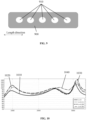
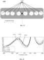
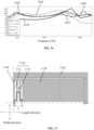
- FIG. 14 is a schematic diagram illustrating frequency response curves of a speaker with a central reinforcing part having different structures according to some embodiments of the present disclosure. As shown in FIG. 14 , the horizontal axis represents frequencies in Hz, and the vertical axis represents sound pressure levels of a sound output by the speaker in dB.
- the output of the speaker in a low-frequency range e.g., frequencies less than 1500 Hz
- a mid-frequency range e.g., 1500 Hz-3000 Hz
- the output of the speaker decreases (e.g., forms a valley) in a relatively high-frequency range (i.e., a frequency range (e.g., 3000 Hz-4500 Hz) in which the central reinforcing part provides a vibration mode), and then increases again at a higher frequency range (e.g., greater than 4500 Hz), which makes the frequency response curve of the speaker not flat enough, and the sound output by the speaker have relatively large fluctuations in sound pressure level.
- a relatively high-frequency range i.e., a frequency range (e.g., 3000 Hz-4500 Hz) in which the central reinforcing part provides a vibration mode
- a higher frequency range e.g., greater than 4500 Hz
- the output of the speaker in the high-frequency range increases as the area ratio ⁇ increases when the central reinforcing part has the non-uniform structure.
- the speaker corresponding to curve 1430 has a lower output at even higher frequencies.
- the valley of the response curve in a high-frequency range i.e., the frequency range in which the central reinforcing part provides the vibration mode
- the valley of the response curve in a high-frequency range may be improved while avoiding a relatively large output at higher frequencies, thereby making the frequency response curve of the speaker flatter over a wider frequency range.
- the vibration transmission part may include a coupling elastic structure and a vibration transmission column (e.g., the vibration transmission column 131 and the coupling elastic structure 132 described above), the driving unit (e.g., a piezoelectric beam) may be connected to one end of the vibration transmission column through the coupling elastic structure, and another end of the vibration transmission column may be connected to the vibrating unit to transmit vibrations, causing the vibrating unit to vibrate, thus causing the speaker to produce sound radiated outward.
- the impedance of the coupling elastic structure is matched with the impedance of the driving unit and the impedance of the vibrating unit, a driving force and a driving displacement of the driving unit may be effectively transferred to the vibrating unit.
- the driving force and the driving displacement of the driving unit may generate a large displacement inside the coupling elastic structure and dissipate energy through thermal losses, failing to transfer the driving force and the driving displacement to the vibrating unit.
- the impedance of the coupling elastic structure is too large (e.g., the stiffness of the coupling elastic structure is too large)
- the driving force and the driving displacement of the driving unit may be limited inside the coupling elastic structure, resulting in reduced driving force and driving displacement transmitted to the vibrating unit. Therefore, the configuration of the coupling elastic structure is crucial in transmitting the driving force and the driving displacement of the driving unit to the vibrating unit.
- the stiffness of the vibration transmission part as a whole may be too large, which is unfavorable for the vibration transmission part to transmit vibrations.
- the stiffness of the vibration transmission part may be adjusted by adjusting a count and a structure (e.g., size, etc.) of the coupling elastic structure, etc., so as to enhance a vibration transmitting effect of the vibration transmission part.
- FIG. 15A is a schematic diagram illustrating an exemplary structure of a coupling elastic structure according to some embodiments of the present disclosure.
- FIG. 15A shows coupling elastic structures 1510, piezoelectric beams 1520, and a vibration transmission column 1530 connected to the coupling elastic structures 1510.
- a count of the piezoelectric beams 1520 may be four and a count of the coupling elastic structures 1510 may be eight.
- Each piezoelectric beam 1520 is connected to two coupling elastic structures 1510.
- one end (also referred to as a fixed end) of the piezoelectric beam 1520 may be connected to a housing (e.g., the back plate 170 described in FIGs.
- a region where the piezoelectric beam 1520 is connected to the back plate may be referred to as a fixed region, and a region on the piezoelectric beam 1520 other than the fixed region may be referred to as a suspended region.
- each piezoelectric beam 1520 may be connected to a vibration transmission column 1530 via two coupling elastic structures 1510, as shown in FIG. 15 A .
- each piezoelectric beam 1520 may be connected to the vibration transmission column 1530 via more than two coupling elastic structures 1510.
- the count of coupling elastic structures 1510 connected to each piezoelectric beam 1520 may be one, three, four, five, etc.
- a material of the coupling elastic structures 1510 may be the same as a material of a substrate. In some embodiments, the material of the coupling elastic structures 1510 may be different from the material of the substrate.
- the coupling elastic structure 1510 may have a straight strip shape (also referred to as a straight-connected coupling elastic structure).
- the coupling elastic structure 1510 may have a straight strip plate shape. Two ends of the straight strip plate-shaped coupling elastic structure along a length direction of the coupling elastic structure may be connected to the free end of the piezoelectric beam 1520 and the vibration transmission column 1530, respectively, to transmit a driving force and a driving displacement of the piezoelectric beam 1520 to the vibrating unit.
- a size (e.g., a length, a thickness) of the coupling elastic structure 1510 may affect a stiffness of the coupling elastic structure 1510, and the stiffness of the coupling elastic structure 1510 may be adjusted by adjusting the size of the coupling elastic structure 1510, such that an impedance of the coupling elastic structure 1510 may match with an impedance of the piezoelectric beam 1520, and the impedance of the coupling elastic structure 1510 may match with an impedance of the vibrating unit.
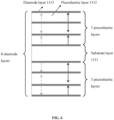
- FIG. 15B is a schematic diagram illustrating a distribution of layers of a piezoelectric beam along a vibration direction according to some embodiments of the present disclosure.
- a vibration direction of the piezoelectric beam 1520 may be the same as a thickness direction of the piezoelectric beam 1520 (and a thickness direction of the coupling elastic structure 1510).
- a thickness h of the piezoelectric beam 1520 and a thickness h o of the coupling elastic structure 1510 are illustrated in FIG. 15B .
- the piezoelectric beam 1520 may include eight electrode layers 1521 and six piezoelectric layers 1522 (e.g., lead zirconate titanate piezoelectric ceramics (PZT)).
- An upper portion and a lower portion of the piezoelectric beam 1520 may include four electrode layers 1521 and three piezoelectric layers 1522, respectively, and the four electrode layers 1521 and the three piezoelectric layers 1522 are distributed alternately.
- a substrate layer 1523 may be located between the two adjacent electrode layers 1521 at a boundary between the upper portion and the lower portion of the piezoelectric beam 1520.
- FIG. 15 B is intended to illustrate the thickness h of the piezoelectric beam 1520 and the thickness h o of the coupling elastic structure 1510. More descriptions of the piezoelectric beam 1520 and the layers thereof may be found in the related descriptions above.
- the size of the coupling elastic structure 1510 may affect a stiffness of the coupling elastic structure 1510.
- the impedance of the coupling elastic structure 1510 may not match the impedance of the piezoelectric beam 1520 and/or the impedance of the vibrating unit.
- a size of the piezoelectric beam 1520 e.g., a length L p of the suspended region of the piezoelectric beam 1520 and the thickness h of the piezoelectric beam 1520 may also affect the impedance matching between the coupling elastic structure 1510 and the piezoelectric beam 1520 (and the vibrating unit).
- the stiffness of the coupling elastic structure 1510 may be adjusted, such that the impedance of the coupling elastic structure 1510 may match with the impedance of the piezoelectric beam 1520, and the impedance of the coupling elastic structure 1510 may match with the impedance of the vibrating unit.
- ⁇ ⁇ (h o /L o 2 )/ ⁇ (h/L p 2 ) may be defined, and a magnitude of ⁇ may determine whether the impedance of the coupling elastic structure 1510 may match with the impedance of the piezoelectric beam 1520 and the impedance of the vibrating unit. For example, if ⁇ is too small, it may indicate that the impedance of the coupling elastic structure 1510 is too small, and the impedance of the coupling elastic structure may not match the impedance of the piezoelectric beam and the impedance of the vibrating unit.
- FIG. 16 is a schematic diagram illustrating frequency response curves of a speaker when a parameter of a coupling elastic structure varies according to some embodiments of the present disclosure.
- the horizontal axis represents frequencies in Hz
- the vertical axis represents sound pressure levels of sound output by the speaker in dB.
- the impedance of the coupling elastic structure is too small compared to the impedance of the piezoelectric beam and the impedance of the vibrating unit, and the impedance of the coupling elastic structure may not match with the impedance of the piezoelectric beam and the impedance of the vibrating unit.
- the driving force and the driving displacement generated by the piezoelectric beam may not be effectively transmitted to the vibrating unit, and the sound pressure level of the sound output by the speaker is relatively low. Therefore, a vlaue of ⁇ may not be less than 0.35.
- the impedance of the coupling elastic structure 1510 may match with the impedance of the piezoelectric beam and the impedance of the vibrating unit, so that the driving force and the driving displacement generated by the piezoelectric beam may be effectively transmitted to the vibrating unit, and the sound pressure level of the sound output by the speaker may be relatively high.
- the impedance of the coupling elastic structure may be too large compared to the impedance of the piezoelectric beam and the impedance of the vibrating unit, so that the impedance of the coupling elastic structure may not match with the impedance of the piezoelectric beam and the impedance of the vibrating unit.
- the value of ⁇ may be in a range of not less than 0.35.
- the value of ⁇ may be in a range of 0.5-40.
- the value of ⁇ may be in a range of 3-36. In some embodiments, the value of ⁇ may be in a range of 5-34.
- the value of ⁇ may be in a range of 7-32. In some embodiments, the value of ⁇ may be in a range of 10-30. In some embodiments, the value of ⁇ may be in a range of 12-28. In some embodiments, the value of ⁇ may be in a range of 15-25.
- a material of the coupling elastic structure 132 may include various anisotropic materials such as metal, a single-layer semiconductor material, a multi-layer semiconductor material, a single-layer polymer material, a multi-layer composite polymer material, a semiconductor and polymer multi-layer composite material, carbon fiber, FR4, or the like.
- a material of the coupling elastic structure 132 may be the same as a material of vibration transmission column 131.
- the impedance of the coupling elastic structure 132 may match the impedance of the vibration transmission column 131, so that vibrations may be effectively transmitted.
- the material of the coupling elastic structure 132 and the material of the vibration transmission column 131 may be the same as a material of a substrate layer (e.g., the substrate layer 1111) of the piezoelectric beam.
- the impedance of the coupling elastic structure 132 may match the impedance of the vibration transmission column 131 and the impedance of the driving unit 110, thereby further facilitating the transmission of the vibrations.
- the coupling elastic structure 132 may be made of the same material as the vibration transmission column 131 to further simplify processing.
- the coupling elastic structure 132 and the vibration transmission column 131 may be made by a one-piece molding process.
- the material of the coupling elastic structure 132 and the material of the vibration transmission column 131 may be different.
- the material of the coupling elastic structure 132 and/or the material of the vibration transmission column 131 may be different from the material of the substrate layer of the piezoelectric beam.
- the use of different materials for the coupling elastic structure 132 and/or the vibration transmission column 131 from the substrate layer of the piezoelectric beam facilitates customization and refinement of parameters of the speaker or performance. It should be noted that the materials used for the coupling elastic structure 132 and the vibration transmission column 131 may be determined based on actual needs and adapted to different application scenarios.
- the size of the coupling elastic structure may be limited, such that the size of the coupling elastic structure may be adjusted only within a permissible area or a limited space to adjust the stiffness of the coupling elastic structure.
- a limited space if the coupling elastic structure has a straight strip shape, a range for adjusting the length of the coupling elastic structure is limited, which in turn limits a range for adjusting the stiffness of the coupling elastic structure.
- the stiffness of the coupling elastic structure may be further adjusted within the limited space, thereby achieving better impedance matching between the coupling elastic structure, the piezoelectric beam, and the vibration unit.
- FIG. 17 is a schematic diagram illustrating another exemplary structure of a coupling elastic structure according to some embodiments of the present disclosure. It may be understood that, compared to FIG. 15A , FIG. 17 only shows a piezoelectric beam 1720, two coupling elastic structures 1710 connected to the piezoelectric beam 1720, and a portion of a vibration transmission column 1730. In addition, a back plate 1740 is shown in FIG.17 , and a fixed end of the piezoelectric beam 1720 is connected to the back plate 1740.
- a projection of the coupling elastic structure 1710 along a vibration direction of the piezoelectric beam 1720 may have at least one bending structure (also referred to as a bending coupling elastic structure). As shown in FIG. 17 , two ends of each of the at least one bending structure (two bending structures in FIG. 17 ) along a length direction of the coupling elastic structure are connected to a free end of the piezoelectric beam 1720 and the vibration transmission column 1730, respectively, and each of the two bending structures bents along a width direction toward the other bending structure connected to the piezoelectric beam 1720.
- the two coupling elastic structures 1710 connected to the same piezoelectric beam 1720 may be denoted as a first coupling elastic structure 1711 and a second coupling elastic structure 1712, respectively.
- Two ends of each of the first coupling elastic structure 1711 and the second coupling elastic structure 1712 along the length direction are connected to the free end of the piezoelectric beam 1720 and the vibration transmission column 1730, respectively.
- the first coupling elastic structure 1711 and the second coupling elastic structure 1712 bent in opposite directions. As shown in FIG.
- a structure formed by the two coupling elastic structures 1710 connected to the same piezoelectric beam 1720 bending once may be referred to as a double-bending coupling elastic structure (or a 2-bending coupling elastic structure).
- the coupling elastic structure 1710 may also be configured as a multi-bending coupling elastic structure, for example, a 4-bending coupling elastic structure, a 6-bending coupling elastic structure, an 8-bending coupling elastic structure, or the like.
- a 4-bending coupling elastic structure as an example, a structure formed by the two coupling elastic structures 1710 connected to the same piezoelectric beam 1720 bending twice (i.e., each of the first coupling elastic structure 1711 and the second coupling elastic structure 1712 bending twice) may be referred to as the 4-bend coupling elastic structure.
- the stiffness of the coupling elastic structure may be adjusted in a limited space, and a better impedance matching between the coupling elastic structure, the piezoelectric beam, and the vibrating unit may be achieved, which is also conducive to the miniaturization of the speaker.
- a count of bendings of the bending coupling elastic structure may be reasonably set according to actual needs (e.g., stiffness requirements), and the present disclosure does not specifically limit this aspect.
- a length L of a region in which the coupling elastic structure 1710 is located may be reduced while ensuring that the impedance of the coupling elastic structure 1710 remains constant, thereby providing more space for the piezoelectric beam structure 1720, increasing the driving force generated by the piezoelectric beam structure 1720, and enhancing the sound pressure level of the sound output by the speaker.
- a length L o of the bending coupling elastic structure 1710 may be set larger in the finite region with the length L, thereby increasing the value of ⁇ , and thus increasing the sound pressure level of the sound output by the speaker.
- the length L o of the coupling elastic structure 1710 refers to a length of a path through which the coupling elastic structure 1710 travels (e.g., the path shown by the arrow in FIG. 17 ).
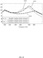
- FIG. 18 is a schematic diagram illustrating frequency response curves of speakers having coupling elastic structures with different structures according to some embodiments of the present disclosure.
- the horizontal axis represents frequencies in Hz
- the vertical axis represents sound pressure levels of sound output by the speaker in dB.
- Curve 1810 represents a frequency response curve of a speaker having a straight-connected coupling elastic structure (e.g., the coupling elastic structure 1510 shown in FIG. 15A ).
- Curve 1820 represents a frequency response curve of a speaker having a 4-bending coupling elastic structure.
- Curve 1830 represents a frequency response curve of a speaker having a 2-bending coupling elastic structure.
- the sound pressure level of the sound output by the speaker with the bending coupling elastic structure is greater (especially in the frequency range of about 1500 Hz-3000 Hz) than the sound pressure level of the sound output by the speaker with the straight-connected coupling elastic structure. Therefore, the bending coupling elastic structure may be configured to reduce the length of the region in which the coupling elastic structure is located while ensuring that the impedance of the coupling elastic structure remains constant, and increase the sound pressure level of the sound output by the speaker.
- the stiffness of the coupling elastic structure may be adjusted by combining the straight-connected coupling elastic structure with the bending coupling elastic structure. In some embodiments, the stiffness of the coupling elastic structure may also be adjusted by adjusting a width of the coupling elastic structure (the straight-connected coupling elastic structure and/or the bending coupling elastic structure).
- a structure or a size of the piezoelectric beam may affect its intrinsic frequency.
- a thickness h of the piezoelectric beam may be positively correlated with a stiffness of the piezoelectric beam
- a length l of the piezoelectric beam may be negatively correlated with the stiffness of the piezoelectric beam, which affects the intrinsic frequency of the piezoelectric beam.
- the thickness h refers to a thickness of the piezoelectric beam along a vibration direction (e.g., the z-direction as shown in FIG. 4 ) of the piezoelectric beam
- the length l refers to a length of the piezoelectric beam along a length direction (e.g., the x-direction as shown in FIG.
- a driving unit (e.g., the piezoelectric beam) of the speaker may be configured so as to enhance the driving capability of the driving unit, and optimize a vibration structure of the speaker, thereby enhancing the sound pressure level of the sound output by the speaker.
- E denotes a material density of the cantilever beam (i.e., the piezoelectric beam)
- l is the length of the cantilever beam (i.e., the piezoelectric beam)
- h denotes the thickness of the cantilever beam (i.e., the piezoelectric beam).
- the piezoelectric beam 1520 may include a fixed region and a suspended region.
- vibration modes of the speaker may be adjusted to achieve mode adjustment of the speaker.
- the intrinsic frequency of the piezoelectric beam 1520 is related to the material density, the length, and the thickness of the piezoelectric beam 1520. Therefore, the vibrational modes of the piezoelectric beam 1520 may be adjusted by adjusting the length and/or the thickness of the piezoelectric beam 1520. As shown in FIGs.
- a length of the suspended region is L p and a thickness of the piezoelectric beam 1520 is h.
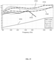
- FIG. 19 is a schematic diagram illustrating frequency response curves of a speaker corresponding to different parameters ⁇ according to some embodiments of the present disclosure.
- the horizontal axis represents frequencies in Hz
- the vertical axis represents sound pressure levels of sound output by the speaker in dB.
- the stiffness of the piezoelectric beam 1520 increases, the frequency of the first resonant peak of the speaker is relatively small, and the speaker outputs a relatively high sound pressure level at low frequencies (e.g., less than 1500 Hz) but outputs a relatively low sound pressure level at mid-and-high frequencies (e.g., greater than 1500 Hz).
- the stiffness of the piezoelectric beam 1520 continues to increase, the frequency of the first resonant peak of the speaker increases, the output sound pressure level of the speaker is relatively high at mid-and-high frequencies but relatively low at low frequencies.
- the stiffness of the piezoelectric beam 1520 is too large, which may cause the frequency of the first resonance peak of the speaker to be too large and limits a displacement output of the piezoelectric beam 1520, and reduce the sound pressure level of the speaker.
- the physical parameter ⁇ of the piezoelectric beam may be relatively large.
- the speaker when the value of ⁇ is in a range of 0.009-0.21, the speaker has a relatively high output sound pressure level over a relatively large frequency range.
- the value of ⁇ may be in a range of 0.01-0.2.
- the value of ⁇ may be in a range of 0.01-0.15.
- the parameter ⁇ may take a value towards a lower end in a range of 0.01-0.2.
- the parameter ⁇ may take a value in a range of 0.01-0.1.
- the parameter ⁇ maybe in a range of 0.02-0.07.
- the parameter ⁇ may be in a range of 0.03-0.06.
- FIG. 20 is a schematic diagram illustrating a structure of a speaker according to some embodiments of the present disclosure.
- a driving force of a speaker 2000 may be positively correlated with an area of a driving unit of the speaker 2000.
- the area of the driving unit refers to a total projection area of one or more piezoelectric beams 2010 in a vibration direction of the driving unit. Therefore, the driving force of the speaker 2000 may be enhanced by increasing the area of the driving unit, thereby enhancing an output sound pressure level of the speaker 2000.
- maximizing an area ratio of the driving unit may significantly enhance the output sound pressure level of the speaker 2000.
- the area of the driving unit in a vibration direction of the piezoelectric beams 2010, is not equivalent to an area of an internal cavity of the back plate 2020 due to a region (region one 2030) occupied by a coupling elastic structure, a region (region two 2040) of a gap between adjacent piezoelectric beams 2010, a region (region three 2050) of a gap between the piezoelectric beams 2010 and the back plate 2020.
- the area of region one 2030 may affect the stiffness of the coupling elastic structure, thus affecting the impedance of the coupling elastic structure and an impedance matching between a driving end and a load end. For example, if the area of region one 2030 is too large, the stiffness of the coupling elastic structure may be too small compared to a stiffness of the drive end and a stiffness of the load end, so that the driving force and displacement are concentrated in the coupling elastic structure, and vibrations generated by the driving unit may not be effectively transmitted to the vibrating unit.
- the stiffness of the coupling elastic structure may be too large compared to the stiffness of the driving end and the stiffness of the load end, and a mass of the coupling elastic structure may be increased, thereby limiting the driving force and displacement output by the driving unit.
- the areas of the two regions may affect processing and manufacturing of the speaker 2000. For example, if the area of region two 2040 and the area of region three 2050 are too small, it may lead to an increase in the difficulty of an etching process or assembly.
- a first projection area of the suspended region of the piezoelectric beam 2010 (i.e., a region outside of region one 2030, region two 2040, and region three 2050) may be defined as S p
- a second projection area of the internal cavity of the back plate 2020 may be defined as S c
- FIG. 21 is a schematic diagram illustrating frequency response curves of a speaker when a physical parameter ⁇ takes different values according to some embodiments of the present disclosure.
- the horizontal axis represents frequencies in Hz and the vertical axis represents sound pressure levels of a sound output by the speaker in dB.
- the driving force of the driving unit may be effectively increased to enhance the output of the speaker.
- ⁇ i.e., the ratio of S p to S c
- the driving force of the driving unit may be effectively increased to enhance the output of the speaker.
- the value of ⁇ approaches 1 an increase in the output of the speaker decreases as the value of ⁇ increases.
- the difficulty of processing the piezoelectric beams 2010 within the internal cavity of the back plate 2020 increases, and the risk of the piezoelectric beams 2010 touching a side wall of the cavity also increases.
- the value of ⁇ may be in a range of 0.35-0.92. In some embodiments, since the speaker requires a certain clearance space for processing and assembling in an actual production process, the value of ⁇ may be in a range of 0.4-0.9. In some embodiments, to further improve the sound pressure level of the speaker, and at the same time reduce the difficulty of processing the piezoelectric beams 2010 within the internal cavity of the back plate 2020 and to avoid the risk of the piezoelectric beams 2010 touching the side wall of the cavity, the value of ⁇ may be in a range of 0.5-0.8.
- a shape of the piezoelectric beam of the speaker has a significant role in modulating the vibration mode of the speaker at mid-and-high frequencies.
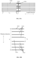
- FIG. 22A and FIG. 22B are schematic diagrams illustrating deformations of piezoelectric beams with different shapes according to some embodiments of the present disclosure.
- FIG.22A shows a deformation of a rectangular piezoelectric beam 2210
- FIG.22 B shows a deformation of a trapezoidal piezoelectric beam 2220.
- the rectangular piezoelectric beam 2210 has a second-order vibration mode at middle frequencies, with relatively small displacements at two ends of the rectangular piezoelectric beam 2210 and a relatively large displacement in the middle of the rectangular piezoelectric beam 2210.
- the shape of the piezoelectric beam may be configured to modulate the output frequency response of the piezoelectric beam of the speaker at mid-and-high frequencies, thereby enhancing the output sound pressure level of the speaker.
- the piezoelectric beam may have at least two different widths at different locations in an extending direction of the piezoelectric beam.
- the piezoelectric beam may have an unequal width in the extending direction.
- the extending direction of the piezoelectric beam may also be understood as a length direction of the piezoelectric beam.
- FIG. 23 is a schematic diagram illustrating a structure of a trapezoidal piezoelectric beam according to some embodiments of the present disclosure. As shown in FIG. 23 , the piezoelectric beam 2220 has gradually varying widths in the extending direction.
- the shape of the piezoelectric beam 2220 By configuring the shape of the piezoelectric beam 2220 to have at least two different widths at different positions, a distribution of mass and a distribution of stiffness of the piezoelectric beam 2220 along the length direction of the piezoelectric beam may be adjusted. As shown in FIG. 22B , the trapezoidal piezoelectric beam 2220 has a relatively small displacement in the middle portion when vibrating at middle frequencies, and the displacement of the piezoelectric beam 2220 may be efficiently transmitted to the coupling elastic structure 2230 and then to the vibrating unit 2240, thereby increasing the vibration of the vibrating unit 2240 and enhancing the output sound pressure level of the speaker.
- a maximum width in different widths (e.g., a width of a wide side of the trapezoidal piezoelectric beam 2220) may be defined as W k
- a minimum width in the different widths (e.g., a width of a narrow side of the trapezoidal piezoelectric beam 2220) may be defined as W z
- the distribution of mass and the distribution of stiffness of the piezoelectric beam 2220 along the length direction may be adjusted to improve the output of the speaker.
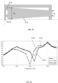
- FIG. 24 is a schematic diagram illustrating frequency response curves of a speaker when a physical parameter ⁇ takes different values according to some embodiments of the present disclosure.
- the horizontal axis represents frequencies in Hz
- the vertical axis represents sound pressure levels of sound output by the speaker in dB.
- the mid-frequency valley is significantly improved. Therefore, in some embodiments, to enhance the output of the speaker in the mid-frequency range, the value of ⁇ may be in a range of 0.5-0.99. In some embodiments, to further enhance the output of the speaker in the mid-frequency range, the value of ⁇ may be in a range of 0.58-0.92. In some embodiments, the value of ⁇ may be in a range of 0.6-0.9.
- the minimum width and the maximum width may be located at two ends of the piezoelectric beam in the extending direction of the piezoelectric beam.
- the piezoelectric beam has a trapezoidal shape, and the minimum width and the maximum width are located at the two ends of the piezoelectric beam in the extension direction of the piezoelectric beam.
- the piezoelectric beam may have other shapes, so as to adjust the distribution of mass and the distribution of stiffness of the piezoelectric beam along the length direction thereof, thereby enhancing the output of the speaker.
- the shape of the piezoelectric beam may include at least one of a rectangular shape, a trapezoidal shape, a stepped shape, or the like.
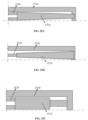
- FIG. 25 A- FIG. 25 F are schematic diagrams illustrating structures of piezoelectric beams with different shapes according to some embodiments of the present disclosure.
- FIG. 25A shows a piezoelectric beam 2510 having a trapezoidal shape and a wide side of the trapezoidal shape being connected to a coupling elastic structure 2520.
- FIG. 25B shows a piezoelectric beam 2510 having a trapezoidal shape and a narrow side of the trapezoidal shape being connected to a coupling elastic structure 2520.
- FIG.25C shows a piezoelectric beam 2510 having two rectangles in a stepped shape and a wide side of the stepped shape being connected to a coupling elastic structure 2520.
- FIG.25 D shows a piezoelectric beam 2510 having two rectangles in a stepped shape and a narrow side of the stepped shape being connected to a coupling elastic structure 2520.
- FIG.25 E shows a piezoelectric beam 2510 having three rectangles in a stepped shape.
- FIG.25 F shows a piezoelectric beam 2510 having two rectangles and one trapezoid in a step shape.
- the piezoelectric beam 2510 may have a trapezoidal shape, the wide side of the trapezoid may be connected to the coupling elastic structure 2520, and a narrow side of the trapezoid may be connected to a back plate 2530 as shown in FIG. 25A .
- the value of the parameter ⁇ of the trapezoidal piezoelectric beam 2510 shown in FIG. 25A may differ from the value of the parameter ⁇ of the trapezoidal piezoelectric beam 2220 shown in FIG. 23 .
- the piezoelectric beam 2510 may have a trapezoidal shape as shown in FIG.
- the piezoelectric beam 2510 may be a combination of a rectangle and a stepped shape, i.e., the piezoelectric beam 2510 may include two rectangles of different sizes and the two rectangles may be connected to form a stepped structure, with a wide side of the stepped structure (i.e., a relatively large rectangle) connected to the coupling elastic structure 2520 and a narrow side of the stepped structure (i.e., a relatively small rectangle) connected to the back plate 2530.
- the piezoelectric beam 2510 may be a combination of a rectangle and a stepped shape, i.e., the piezoelectric beam 2510 may include two rectangles of different sizes and the two rectangles may be connected to form a stepped structure, with a narrow side of the stepped structure (i.e., a relatively small rectangle) connected to the coupling elastic structure 2520 and a wide side of the stepped structure (i.e., a relatively large rectangle) connected to the back plate 2530.
- the minimum width and the maximum width are located at the two ends of the piezoelectric beam in the extending direction of the piezoelectric beam, respectively.
- the minimum width may be disposed in a central region of the piezoelectric beam in the extending direction of the piezoelectric beam.
- FIGs. 25E-25F illustrate embodiments in which the minimum width is located in the central region of the piezoelectric beam in the extending direction thereof.
- the piezoelectric beam 2510 may include three rectangles, the three rectangles may include two relatively large rectangles and one relatively small rectangle, the three rectangles may be sequentially connected and the relatively small rectangle may be disposed between the two relatively large rectangles to form a stepped structure, with two ends of the stepped structure (i.e., the two relatively large rectangles) being connected to coupling elastic structures 2520 and the back plate 2530, respectively.
- FIG. 25E the piezoelectric beam 2510 may include three rectangles, the three rectangles may include two relatively large rectangles and one relatively small rectangle, the three rectangles may be sequentially connected and the relatively small rectangle may be disposed between the two relatively large rectangles to form a stepped structure, with two ends of the stepped structure (i
- the piezoelectric beam 2510 may include two rectangles and one trapezoid, the two rectangles may include two rectangles of different sizes, the two rectangles and the one trapezoid may be sequentially connected, and a relatively small rectangle may be disposed between a relatively large rectangle and the trapezoid to form a stepped structure.
- a wide side of the trapezoid may be connected to the relatively small rectangle, one end of the stepped structure (the relatively large rectangle) may be connected to the coupling elastic structure 2520, and the other end of the stepped structure (a narrow side of the trapezoid) may be connected to the back plate 2530.
- the value of the parameter ⁇ (the ratio of the minimum width W z to the maximum width W k ) of the piezoelectric beam may still be in the range of 0.5-0.99.
- a count of piezoelectric beams may also be configured to adjust the stiffness of the driving unit, thereby improving the vibration mode of the speaker at middle frequencies and enhancing the output of the speaker.
- FIG. 26 is a schematic diagram illustrating a structure including a plurality of piezoelectric beams according to some embodiments of the present disclosure.
- a speaker may include a plurality of piezoelectric beams 2610, and the plurality of piezoelectric beams 2610 may be spaced apart in a width direction.
- Each of the plurality of piezoelectric beams 2610 may include a fixed region 2611 and a suspended region 2612.
- each piezoelectric beam 2610 may be connected to a back plate at its fixed region 2611, and a free end of each piezoelectric beam 2610 may be connected to a coupling elastic structure 2620.
- the stiffness of the driving unit may be adjusted so as to improve the output of the speaker.
- the vibration mode of the speaker at mid-and-high frequencies may be adjusted, and the second-order vibration mode of the piezoelectric beam of the speaker that occurs at middle frequencies may be effectively adjusted, thereby improving the valley of the frequency response of the speaker.
- the piezoelectric beam may include a piezoelectric layer and an electrode layer, the piezoelectric layer may be configured to deform in response to an electrical signal, and the deformation may drive the piezoelectric beam to generate vibrations.
- the mid-frequency vibration mode of the piezoelectric beam may be modulated by adjusting an electrode distribution (or referred to as the electrode layer) of the piezoelectric beam, which improves the valley of the frequency response of the speaker.
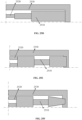
- FIG. 27A and FIG. 27B are schematic diagrams illustrating deformations of piezoelectric beams with different electrode distributions according to some embodiments of the present disclosure.
- a surface of the piezoelectric beam 2710 shown FIG. 27A is fully covered by an electrode 2720, and the piezoelectric beam 2710 shown in FIG.27B is partially covered by the electrode 2720 at an end of the piezoelectric beam 2710 near a fixed region 2711.
- FIG. 27A and FIG. 27B are schematic diagrams illustrating deformations of piezoelectric beams with different electrode distributions according to some embodiments of the present disclosure.
- a surface of the piezoelectric beam 2710 shown FIG. 27A is fully covered by an electrode 2720
- the piezoelectric beam 2710 shown in FIG.27B is partially covered by the electrode 2720 at an end of the piezoelectric beam 2710 near a fixed region 2711.
- FIG. 27A and FIG. 27B are schematic diagrams illustrating deformations of piezoelectric beams with different electrode distributions
- the piezoelectric beam 2710 when the surface of the piezoelectric beam 2710 is fully covered by the electrode 2720, the piezoelectric beam 2710 is subjected to a bending deformation at all positions of the piezoelectric beam 2710 along a length direction thereof when a voltage is applied to the piezoelectric beam 2710. As in FIG.
- the vibration mode of the piezoelectric beam 2710 may be effectively regulated in different frequency ranges, thereby improving the output effect of the speaker.
- the surface of the piezoelectric beam being fully (or partially) covered by electrodes refers to an area of the piezoelectric layer being equal to an area of the substrate layer, with the electrode layer fully (or partially) covering the piezoelectric layer; or refer to the piezoelectric layer and the electrode layer fully (or partially) covering the substrate layer, which is not limited in the present disclosure.
- the aforementioned situations are referred to as the surface of the piezoelectric beam being fully (or partially) covered by electrodes.
- FIG. 28 is a schematic diagram illustrating a distribution of electrodes on a piezoelectric beam according to some embodiments of the present disclosure.
- FIG. 29A and FIG. 29B are schematic diagrams illustrating simulated deformations of piezoelectric beams with different electrode distributions according to some embodiments of the present disclosure.
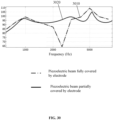
- FIG.30 is a schematic diagram illustrating frequency response curves of a speaker corresponding to the two electrode distributions shown in FIG.29 A and FIG.29 B.
- FIG. 29A is a schematic diagram illustrating a simulated deformation of a piezoelectric beam 2710 fully covered by electrodes 2720 in a length direction of the piezoelectric beam 2710.
- FIG.29 B is a schematic diagram illustrating a simulated deformation of a piezoelectric beam 2710 partially covered by electrodes 2720 near a fixed end of the piezoelectric beam 2710.
- the horizontal axis represents frequencies in Hz
- the vertical axis represents sound pressure levels of sound output by the speaker in dB.
- Curve 3010 represents a frequency response curve of a speaker when the piezoelectric beam 2710 is fully covered by the electrodes 2720
- curve 3020 represents a frequency response curve of the speaker when the piezoelectric beam 2710 is partially covered by the electrodes 2720.
- the piezoelectric beam 2710 that is partially covered by the electrodes 2720 near the fixed end better improves the valley in the frequency response curve in a mid-frequency range (e.g., around 2500 Hz), resulting in a flatter frequency response curve and improved speaker output.
- a mid-frequency range e.g., around 2500 Hz
- partial coverage of the piezoelectric layer can flatten the frequency response curve of the speaker, thereby enhancing the output effect of the speaker.
- an end (i.e., the free end) of the piezoelectric beam 2710 opposite to the fixed region 2711 in the extending direction of the piezoelectric beam 2710 may be connected to the vibration transmission part.
- a distance between a center of the electrode layer and the fixed region 2711 may be less than a distance from the center of the electrode layer to the end of the piezoelectric beam 2710 connected to the vibration transmission part.
- the electrode may be provided at a position of the piezoelectric beam 2710 near the fixed end.
- a size of the electrode distributed on the piezoelectric beam may be configured so that the vibration mode of the piezoelectric beam may be effectively modulated.
- a relationship between a length of the electrode distributed on the piezoelectric beam and a length of the piezoelectric beam may have an important effect in modulating the vibration mode of the piezoelectric beam.
- the electrode 2720 may be rectangular, a length of the electrode 2720 covering a suspended region 2712 of the piezoelectric beam 2710 may be defined as L a and a length of the suspended region 2712 may be defined as L p .
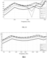
- FIG. 31 is a schematic diagram illustrating frequency response curves of a speaker when a physical parameter ⁇ takes different values according to some embodiments of the present disclosure.
- ⁇ gradually decreases (e.g., from 1 to 0.06), the mid-frequency valley of the speaker is improved, but the low-frequency output decreases.
- the value of ⁇ may be in a range of 0.1-0.9. In some embodiments, to make the speaker have a relatively flat output at mid-frequencies, the value of ⁇ may be in a range of 0.2-0.6. In some embodiments, to reduce a difference between the low-frequency output and the mid-frequency output of the speaker, the value of ⁇ may be in a range of 0.3-0.6. In some embodiments, the value of ⁇ may be in a range of 0.3-0.6. In some embodiments, the value of ⁇ may be in a range of 0.3-0.5.
- a width of the electrode may affect a size of a deformation region on the piezoelectric beam. Therefore, the width of the electrode on the piezoelectric beam may be adjusted to regulate the driving force generated by the piezoelectric beam, thereby improving the output of the speaker.
- the width of the electrode 2720 on the suspended region 2712 may be defined as W a
- FIG. 32 is a schematic diagram illustrating frequency response curves of a speaker when a physical parameter ⁇ takes different values according to some embodiments of the present disclosure.
- the value of the physical parameter ⁇ increases (e.g., the value of ⁇ gradually increases from 0.2 to 1)
- the width W a of the electrode 2720 and the width W p of the suspended region of the piezoelectric beam 2710 gradually approach each other, and the output sound pressure level of the speaker gradually increases.
- the value of ⁇ may be in a range of 0.3-1 to ensure that the speaker has a relatively high output sound pressure level. In some embodiments, the value of ⁇ may be in a range of 0.4-1. In some embodiments, the value of ⁇ may be in a range of 0.5-1.
- the electrode layer may include a first region (or first electrode) near a fixed region (or referred to as a fixed end) and a second region (or second electrode) near a coupling elastic structure (or referred to as a free end).
- a width of the second electrode provided near the free end of the piezoelectric beam is too large, the mid-frequency vibration mode of the piezoelectric beam may tend to have an effect of the piezoelectric beam being fully covered by the electrode, resulting in an obvious mid-frequency valley in the frequency response curve of the speaker.
- the electrode distribution may be gradient.
- the width of the first region may be greater than the width of the second region. This configuration may effectively modulate the vibration mode of the piezoelectric beam, thereby improving the output sound pressure level while improving the mid-frequency valley.
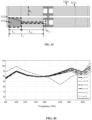
- FIG. 33 is a schematic diagram illustrating a distribution of electrodes on a piezoelectric beam according to some embodiments of the present disclosure.
- a piezoelectric beam 3310 may be provided with a first electrode 3321 having a relatively large width and a second electrode 3322 having a relatively small width.
- the first electrode 3321 and the second electrode 3322 may both be rectangular structures. It should be noted that the distribution of the electrodes (the first electrode 3321 and the second electrode 3322) on only one piezoelectric beam 3310 is shown in FIG. 33 , and the distribution of the electrodes on other piezoelectric beams 3310 may refer to the above-described distribution, which will not be repeated herein.
- the width of the second electrode 3322 may be defined as W af
- a width of a suspended region 3312 (or the piezoelectric beam 3310) may be defined as W p
- FIG. 34 is a schematic diagram illustrating frequency response curves of a speaker when a physical parameter ⁇ takes different values according to some embodiments of the present disclosure.
- the value of ⁇ may be in a range of 0.01-0.89. In some embodiments, to enhance the output of the speaker in the full-frequency range, the value of ⁇ may be in a range of 0.01-0.7. In some embodiments, to reduce a difference between the output of the speaker at the low and mid frequencies and the output of the speaker at the mid and high frequencies, the value of ⁇ may be in a range of 0.1-0.7. In some embodiments, the value range of ⁇ may also be selected according to the needs of different application scenarios.
- the value of ⁇ may be in a range of 0.01-0.4.
- the value of ⁇ may be in a range of 0.4-0.9.
- a length of the second electrode 3322 on the piezoelectric beam 3310 near a free end may be defined as L af
- a length of the suspended region 3312 may be defined as L p
- the length L af of the second electrode 3322 may affect a length of a region on the piezoelectric beam 3310 that is involved in generating a driving force.
- the larger the L af is the closer the deformation of the piezoelectric beam 3310 at a middle frequency is to the case in which the piezoelectric beam 3310 is fully covered by electrodes, which results in the mid-frequency valley in the output frequency response curve of the speaker being more obvious.
- FIG. 35 is a schematic diagram illustrating frequency response curves of a speaker when a physical parameter x takes different values according to some embodiments of the present disclosure.
- the value of x may be in a range of 0.01- 0.69. In some embodiments, to further enhance the output of the speaker in the full frequency range, the value of x may be in a range of 0.1-0.5. In some embodiments, to reduce a difference between the output of the speaker at the low and mid frequencies and the output of the speaker at the mid and high frequencies, the value of x may be in a range of 0.2-0.45. In some embodiments, the value range of x may be selected according to the needs of different application scenarios. For example, in a scenario with a high requirement for mid-and-high frequencies, the value of ⁇ may be in a range of 0-0.4. As another example, in a scenario with a high requirement for low-and-mid frequencies, the value of ⁇ may be in a range of 0.4-0.7.
- FIG. 36 is a schematic diagram illustrating another distribution of electrodes on a piezoelectric beam according to some embodiments according to the present disclosure.
- the electrodes provided on the piezoelectric beam 3610 may include a trapezoidal electrode and a rectangular electrode.
- an electrode layer may include a first region 3621 (or referred to as a first electrode 3621) near a fixed region and a second region 3622 (or referred to as a second electrode 3622) near a coupling elastic structure.
- the first electrode 3621 may be a rectangle electrode with a relatively large width
- the second electrode 3622 may be a trapezoid electrode with a relatively small width.
- the width of the rectangular first electrode 3621 may be the same width as a width of a wide side of the trapezoidal second electrode 3622. It should be noted that only one distribution of the electrodes on the piezoelectric beam is shown in FIG. 36 , and the distribution of the electrodes on other piezoelectric beams may refer to the above-described distribution, and will not be repeated herein.
- a vibration mode of the piezoelectric driver may be effectively modulated, a mid-frequency valley of the speaker may be improved, and an output sound pressure level of the speaker may be improved.
- the length of the rectangular first electrode 3621 covering a suspended region 3612 may be defined as L aj
- the length of the second electrode 3622 may be defined as L at
- a length of the suspended region 3612 may be defined as L p
- FIG. 37 is a schematic diagram illustrating frequency response curves of a speaker when a physical parameter z takes different values according to some embodiments of the present disclosure.
- a mid-frequency (e.g., near 3000 Hz) valley of the speaker moves to high frequencies and the sound pressure level at the valley gradually increases.
- an output of the speaker at low frequencies decreases.
- the value of z may be in a range of 0.05-0.9.
- the value of z may be in a range of 0.05-0.6. In some embodiments, to ensure the output of the speaker at low frequencies and to better reduce the effect of the mid-frequency valley on the output of the speaker at middle frequencies, the value of z may be in a range of 0.1-0.5.
- a width of a narrow side of the second electrode 3622 may be defined as W a2
- a width of the suspended region 3612 may be defined as W p
- FIG. 38 is a schematic diagram illustrating frequency response curves of a speaker when a physical parameter m takes different values according to some embodiments of the present disclosure.
- the value of m may be in a range of 0.1-0.9.
- the value of m may be in a range of 0.1-0.7. In some embodiments, to improve the output of the speaker at low frequencies and reduce the effect of the mid-frequency valley on the output of the speaker at mid frequencies, the value of m may be in a range of 0.3-0.7.
- the length of the second electrode 3622 may be defined as L at
- FIG. 39 is a schematic diagram illustrating frequency response curves of a speaker when a physical parameter y takes different values according to some embodiments of the present disclosure.
- an effect of the physical parameter y on the output sound pressure level of the speaker is opposite to an effect of the physical parameter z on the output sound pressure level of the speaker.
- the value of y gradually increases, for example, from 0 to 0.95, the mid-frequency (e.g., around 2500 Hz) valley of the speaker moves to high frequencies, and the sound pressure level at the valley gradually increases.
- the output of the speaker at low frequencies decreases.
- the value of y may be in a range of 0.1-0.95. In some embodiments, to achieve a relatively flat output of the speaker over a wider range of low-and-mid frequencies, the value of y may be in a range of 0.3-0.95. In some embodiments, to ensure the output of the speaker at low frequencies and to better reduce the effect of the mid-frequency valley on the output of the speaker at middle frequencies, the value of y may be in a range of 0.5-0.8.
- FIG. 40 is a schematic diagram illustrating another distribution of an electrode on a piezoelectric beam according to some embodiments of the present disclosure.
- the electrode 4020 may have a trapezoidal structure.
- a wide side of the trapezoidal electrode 4020 may be provided on the piezoelectric beam 4010 near a fixed end, and a narrow side of the trapezoidal electrode 4020 may be provided on the piezoelectric beam 4010 near a free end (i.e., an end near a coupling elastic structure).
- the distribution of the electrode on only one piezoelectric beam is shown in FIG.40 , and the distribution of the electrodes on other piezoelectric beams may refer to the above distribution, which will not be repeated here.
- a vibration mode of the piezoelectric beam may be effectively modulated, thereby improving the mid-frequency valley of the speaker and improving the output sound pressure level of the speaker.
- a width of the trapezoidal electrode 4020 near the coupling elastic structure (or referred to as a narrow-side width) may be defined as W a2 '
- a width of a suspended region 4012 may be defined as W p
- FIG. 41 is a schematic diagram illustrating frequency response curves of a speaker when a physical parameter ⁇ ' takes different values according to some embodiments of the present disclosure.
- a physical parameter ⁇ ' decreases, e.g., from 1 to 0.005
- a mid-frequency (e.g., near 2500 Hz) valley of the speaker gradually moves to high frequencies, the sound pressure level at the valley gradually increases, and an output of the speaker at mid-and-high frequencies increases.
- the output of the speaker at low frequencies decreases.
- the value of ⁇ ' may be in a range of 0.05-0.8. In some embodiments, to achieve a relatively flat output of the speaker over a wider range of low-and-mid frequencies, the value of ⁇ ' may be in a range of 0.05-0.6. In some embodiments, to ensure the output of the speaker at low frequencies and to better reduce an effect of the mid-frequency valley on the output of the speaker at middle frequencies, the value of ⁇ ' may be in a range of 0.2-0.5.
- a length of the trapezoidal electrode 4020 covering the suspended region 4012 may be defined as L aj1
- a length of the suspended region 4012 may be defined as L p
- FIG. 42 is a schematic diagram illustrating frequency response curves of a speaker when a physical parameter ⁇ ' takes different values according to some embodiments of the present disclosure.
- a mid-frequency (e.g., near 4000 Hz) valley of the speaker becomes more obvious (e.g., the sound pressure level at the valley decreases) as the value of ⁇ ' increases, e.g., from 0.05 to 1.
- the output of the speaker at low frequencies increases as the value of ⁇ ' increases.
- the value of ⁇ ' may be in a range of 0.1-0.9.
- the value of ⁇ ' may be in a range of 0.1-0.7. In some embodiments, to enhance the output of the speaker at mid-and-high frequencies while ensuring the output of the speaker at low frequencies, the value of ⁇ ' may be in the range of 0.2-0.6.
- FIG. 43 is a schematic diagram illustrating frequency response curves of a speaker corresponding to different electrode shapes according to some embodiments of the present disclosure.
- a piezoelectric beam partially covered by a trapezoidal electrode and a piezoelectric beam partially covered by a trapezoidal electrode and a rectangular electrode better realize the modulation of a vibration pattern of the piezoelectric beam at middle frequencies (e.g., near 2,500 Hz), thereby enhancing an output sound pressure level of the speaker and improving a mid-frequency valley of the speaker.
- middle frequencies e.g., near 2,500 Hz
- the piezoelectric beam partially covered by a trapezoidal electrode and a rectangular electrode achieves the best effect.
- the distribution of electrodes on the piezoelectric beam may be configured in the form of a combination of a trapezoidal shape and a rectangular shape. It should be noted that the distribution of the electrodes on the piezoelectric beam may also be configured based on actual needs, which is not limited by the present disclosure.
- an electrode layer may include a first region (or referred to as a first electrode) near a fixed region, a second region (or referred to as a second electrode) near a coupling elastic structure, and a third region (or referred to as a third electrode) connecting the first region and the second region, wherein a width of the third region may be smaller than a width of the first region and a width of the second region.
- FIG. 44 is a schematic diagram illustrating another distribution of electrodes on a piezoelectric beam according to some embodiments of the present disclosure.
- a piezoelectric beam 4410 may be provided with a first electrode 4421, a second electrode 4422, and a third electrode 4423 having varying widths, and the first electrode 4421, the second electrode 4422, and the third electrode 4423 are all rectangular structures.
- the first electrode 4421 with the largest width may be disposed at an end of the piezoelectric beam 4410 near a fixed region 4411
- the second electrode 4422 with a medium width may be disposed at an end of the piezoelectric beam 4410 near a coupling elastic structure 4430
- the third electrode 4423 with the smallest width may be disposed in a middle region of the piezoelectric beam 4410.
- the third electrode 4423 is disposed between the first electrode 4421 and the second electrode 4422, and the first electrode 4421, the second electrode 4422, and the third electrode 4423 form a double-step structure. It should be noted that the distribution of the electrodes (the first electrode 4421, the second electrode 4422, and the third electrode 4423) on only one piezoelectric beam 4410 is shown in FIG. 44 , and the distribution of the electrodes on other piezoelectric beams may refer to the above-described distribution, which will not be repeated herein.
- a vibration mode of the piezoelectric beam 4410 at middle frequencies may be close to a vibration mode of the piezoelectric beam fully covered by electrodes, so that the output sound pressure level of the speaker has an obvious mid-frequency valley. If the width and the length of the second electrode 4422 of the piezoelectric beam 4410 near the free end are too small, an area of a portion of the piezoelectric beam 4410 that is covered by the second electrode 4422 and involved in generating a driving force may be too small, and thus the enhancement of the output sound pressure level of the speaker is not obvious.
- a length of the second electrode 4422 may be defined as L af1
- a length of a suspended region 4412 may be defined as L p
- FIG. 45 is a schematic diagram illustrating frequency response curves of a speaker when a physical parameter ⁇ takes different values according to some embodiments of the present disclosure.
- ⁇ decreases gradually (e.g., from 1 to 0)
- a mid-frequency (e.g., near 2500 Hz) valley of the speaker gradually increases, and thus an output of the speaker at mid-and-high frequencies is improved while an output of the speaker at low frequencies is reduced.
- the value of ⁇ may be in a range of 0.1-0.8.
- the value of ⁇ may be in a range of 0.1-0.6. In some embodiments, to further enhance the output of the speaker at low frequencies while reducing the effect of the mid-frequency valley on the mid-frequency output of the speaker, the value of ⁇ may be in a range of 0.2-0.5.
- the vibration mode of the piezoelectric beam 4410 at middle frequencies may be close to the vibration mode of the piezoelectric beam fully covered by electrodes, which makes the mid-frequency valley of the speaker obvious. If the width W af1 of the second electrode 4422 is too small, the area of the portion of the piezoelectric beam 4410 that is covered by the second electrode 4422 and involved in generating the driving force may be too small, so that the enhancement of the output sound pressure level of the speaker is not obvious.
- a range of a ratio of the width W af1 of the second electrode 4422 to the width W p of the suspended region 4412 may be the same as a range of the ratio ⁇ of the width W af of the third electrode 4423 (or the second electrode 3322 shown in FIG. 33 ) to the width W p of the suspended region 4412 (or the suspended region 3312 shown in FIG. 33 ), i.e., the ratio of W af1 to W p may be in a range of 0.01-0.89.
- the ratio of W af1 to W p may be in a range of 0.01-0.7.
- the ratio of W af1 to W p may be in a range of 0.1-0.7. In some embodiments, the ratio of W af1 to W p may be determined according to the needs of different application scenarios. For example, in a scenario with a high requirement for mid-and-high frequencies, the ratio of W af1 to W p may be in a range of 0.01-0.4. As another example, in a scenario with a high requirement for low-and-mid frequencies, the ratio of W af1 to W p may be in a range of 0.4 to 0.9.
- FIG. 46 is a schematic diagram illustrating another distribution of electrodes on a piezoelectric beam according to some embodiments of the present disclosure.
- the electrodes provided on the piezoelectric beam may have a particular shape.
- the second region may be arc-shaped.
- the electrode provided on the piezoelectric beam 4610 may be double-arc shaped.
- the electrode 4620 may have an arc-shaped groove at each of the two ends of the piezoelectric beam 4610.
- a shape of the arc-shaped groove may include a circular arc, an elliptical arc, a hyperbolic arcs, or the like. It should be noted that the distribution of electrodes on only one of the piezoelectric beam 4610 is shown in FIG. 46 , and the distribution of electrodes on other piezoelectric beams may refer to the above-mentioned distribution, which will not be repeated herein.
- FIG. 47 is a schematic diagram illustrating frequency response curves of a speaker provided with a double-arc electrode and a fully-covered electrode, respectively, according to some embodiments of the present disclosure.
- a mid-frequency (e.g., around 3000 Hz) valley moves to high frequencies and the sound pressure level at the valley is improved when the piezoelectric beam is provided with the double-arc electrode. Therefore, the speaker with a piezoelectric beam provided with the double-arc electrode may better adjust the mid-frequency valley.
- FIG. 48 is a schematic diagram illustrating a structure of an electrode lead-out manner on a piezoelectric beam according to some embodiments of the present disclosure.
- the piezoelectric beam includes a plurality of piezoelectric layers 4810 which may be configured to deform in response to an electrical signal, the deformation of the plurality of piezoelectric layers may drive the piezoelectric beam to generate vibrations.
- each piezoelectric layer 4810 of the plurality of piezoelectric layers 4810 may be provided with an electrode layer 4820 (or referred to as an electrode) on each side of the piezoelectric layer, including a positive electrode layer 4821 and a negative electrode layer 4822.
- the positive electrode layer 4821 may be connected to a positive voltage pole and the negative electrode layer 4822 may be connected to a negative voltage pole.
- corresponding voltages may be applied to the electrodes 4820 of different piezoelectric layers 4810 such that the piezoelectric layers 4810 may deform under a piezoelectric action. Therefore, a plurality of electrode layers 4820 (the positive electrode layers 4821) may be connected to the positive pole of a power supply, and a plurality of electrode layers 4820 (the negative electrode layers 4822) may be connected to the negative pole of the power supply. In some embodiments, the plurality of electrode layers 4820 may be led out using techniques such as soldering wires or bonding a flexible printed circuit (FPC) using solder or conductive adhesive.
- FPC flexible printed circuit
- the lead-out of the electrode layer(s) may be completed quickly and easily.
- soldering wires to each layer may result in too many solder wires, a complex process, poor product yields and stability, and larger product sizes. The above problems may be effectively improved by configuring electrode leads.
- FIG. 49A and FIG. 49B are schematic diagrams illustrating electrodes on a piezoelectric beam according to some embodiments of the present disclosure.
- FIG. 49A shows an electrode layer (or referred to as a positive electrode layer) to which a positive voltage is applied
- FIG. 49B shows an electrode layer (or referred to as a negative electrode layer) to which a negative voltage is applied.
- FIG. 49A and FIG. 49B are illustrative only, and in some embodiments, the polarity of the electrodes shown in FIG. 49A and FIG. 49B may be reversed.
- FIG. 49A may show an electrode layer (or referred to as the negative electrode layer) to which a negative voltage is applied
- FIG. 49A may show an electrode layer (or referred to as the negative electrode layer) to which a negative voltage is applied
- each piezoelectric layer on the piezoelectric beam may include a positive electrode layer and a negative electrode layer, and along a vibration direction of the piezoelectric beam 4910, the positive electrode layer and the negative electrode layer may be disposed on two sides of the piezoelectric layer, respectively.
- the piezoelectric beam 4910 may include a fixed region 4911 and a suspended region 4912.
- the piezoelectric beam 4910 may be connected to a back plate 4930 in the fixed region 4911, which does not have, or has a minor contribution to providing a driving force due to the fixed configuration of the fixed region 4911. Therefore, in some embodiments, the structure of the electrodes may be configured in the fixed region 4911 without affecting the vibration of the piezoelectric beam 4910.
- a negative electrode layer 4920 may include a first electrode 4921 disposed on the fixed region 4911, a lead structure 4922 disposed on a side of the piezoelectric beam 4910, and a second electrode 4923 disposed on the suspended region 4912, wherein the side of the piezoelectric beam 4910 on which the lead structure 4922 is provided refers to a side of the piezoelectric beam 4910 that extends along a width direction of the piezoelectric beam 4910.
- the first electrode 4921 thereon may lead out the second electrode 4923 disposed on the suspended region 4912 and connect the second electrode 4923 to the lead structure 4922.
- the lead structure 4922 may lead the electrodes of each layer that are required to be applied with the same voltage.
- the lead structure 4922 of each piezoelectric layer may be interconnected to conduct the negative electrode layer of each piezoelectric layer.
- the positive electrode layer shown in FIG. 49A may have the same or similar configuration as the electrode layer shown in FIG. 49 B .
- the positive electrode layer 4920' shown in FIG. 49A may include a first electrode 4921', a lead structure 4922', and a second electrode 4923', and the lead structure 4922' of each piezoelectric layer may be connected so as to conduct the positive electrode layer of each piezoelectric layer.
- the side of the piezoelectric beam may be provided with two lead structures, one of the two lead structures may be electrically connected to a plurality of positive electrode layers of the plurality of piezoelectric layers, and the other of the two lead structures may be electrically connected to a plurality of negative electrode layers of the plurality of piezoelectric layers.
- electrode layers applied with different voltages may not be electrically connected.
- the first electrode 4921' of each positive electrode layer and the first electrode 4921 of the negative electrode layer may not be interconnected.
- the conduction structure 4922' of each positive electrode layer and the lead structure 4922 of each negative electrode layer may also not be overlapped, so that the positive electrodes and the negative electrodes do not conduct.
- a width of the lead structure of each positive electrode layer and a width of the lead structure of each negative electrode layer may both be less than half of a width of the piezoelectric beam.
- the half-width of the piezoelectric beam 4910 may be defined as W j
- a width of the electrode layer covering the fixed region may be defined as W a
- the physical parameter WW may be not less than 5 ⁇ m. In some embodiments, to further reduce the risk of conduction between the positive electrodes and the negative electrodes, the physical parameter WW may be not less than 10 ⁇ m.
- the two lead structures may be disposed on a side of the piezoelectric beam that extends along the width direction of the piezoelectric beam. In some embodiments, the two lead structures may be disposed on two sides of the piezoelectric beam that extend along a length direction of the piezoelectric beam, respectively.
- FIG. 50A and FIG. 50B are schematic diagrams illustrating structures of a piezoelectric beam according to some embodiments of the present disclosure.
- FIG.50A shows the two structures shown in FIG.49A and FIG.49B
- FIG.50 B shows an enlarged view of the C region in FIG.50A
- FIG.50C shows a cross-section view of the piezoelectric beam shown in FIG. 50A along section A-A
- FIG.50D shows a cross-section view of the piezoelectric beam shown in FIG. 50A along section B-B.
- the first electrode 4921 may connect electrode layers of each piezoelectric layer that require a voltage of a same polarity (e.g., a negative voltage) through a lead structure 4922 located on the side of the piezoelectric beam 4910 that extends along the width direction of the piezoelectric beam 4910 (or on a side of the width direction of the piezoelectric beam that corresponds to the fixing region 4911), and the first electrode 4921' may connect electrode layers of each piezoelectric layer that require a voltage of a same polarity (e.g., a negative voltage) through a lead structure 4922' located on the side of the piezoelectric beam 4910 that extends along the width direction of the piezoelectric beam 4910 (or on a side of the width direction of the piezoelectric beam that corresponds to the fixing region 4911).
- the lead structure 4922 may be referred to as a side negative electrode and the lead structure 4922' may be referred to as a side positive electrode.
- the first electrode 4921 may not overlap with the first electrode 4921' in a projection plane along the vibration direction of the piezoelectric beam 4910, and correspondingly, the side negative electrode may not overlap with the side positive electrode.
- a plurality of negative electrode layers 4920 and a plurality of positive electrode layers 4920' may be disposed on the piezoelectric beam 4910 along the vibration direction of the piezoelectric beam 4910 (or along a thickness direction of the fixed region 4911). Within a projection range of the fixed region 4911, the plurality of negative electrode layers 4920 and the plurality of positive electrode layers 4920' may also be provided with avoidance regions, respectively. As shown in FIG.
- the positive electrode layers 4920' which require to be applied with a positive voltage
- the negative electrode layers 4920 which require to be applied with a negative voltage
- avoidance regions each of which has a length of L k such that the negative electrode layers 4920 do not conduct with the side positive electrodes.
- avoidance regions each of which has a length of L k may be provided between the positive electrode layers 4920' which require to be applied with a positive voltage and the side negative electrode, so that the positive electrode layers 4920' do not conduct with the side negative electrodes.
- the length L k needs to be within a preset range to ensure that the positive electrode layers 4920' and the negative electrode layers 4920 are connected to the corresponding side electrodes, respectively.
- the value of L k may be not less than 2 ⁇ m. In some embodiments, the value of L k may be not less than 5 ⁇ m. In some embodiments, the value of L k may be not less than 10 ⁇ m.
- connection between the fixed region 4911 of the piezoelectric beam 4910 and the back plate may be achieved by gluing, mechanical snap-fits, bonding, or the like.
- the fixed region 4911 of the piezoelectric beam 4910 and the back plate may be electrically connected by soldering wires, binding, or the like.
- the piezoelectric beam 4910 may also be electrically and mechanically connected to the back plate through solder joints.
- the piezoelectric beam 4910 may be electrically connected to the back plate through solder joints while using adhesive for mechanical reinforcement.
- the first electrode 4921 and the first electrode 4921' in the fixed region 4911 may serve as electrical connection solder points.
- the first electrode 4921 and the first electrode 4921' on the top surface of the piezoelectric beam 4910 may be used as electrical connection solder points, achieving both electrical and mechanical connection between the piezoelectric beam 4910 and the back plate.
- FIG. 51A is a schematic diagram illustrating another structure of a piezoelectric beam according to some embodiments of the present disclosure.
- FIG.51B is a schematic diagram illustrating an enlarged view of region D in FIG.51A .
- FIG.51C is a schematic diagram illustrating a cross-section view of the piezoelectric beam shown in FIG.51A along section A-A.
- FIG.51A shows positive electrodes and negative electrodes to which positive and negative voltages are applied, respectively. In some embodiments, as shown in FIGs.
- the lead structure 4922' of the positive electrode layers 4920 (or referred to as side positive electrodes) and the lead structure 4922 of the negative electrode layers 4920' (or referred to as side negative electrodes) may be located on two sides of the piezoelectric beam 4910 that extend along a length of the piezoelectric beam 4910, respectively.
- the negative electrode layers 4920 and the positive electrode layers 4920' may also be provided with an avoidance region, respectively. As shown in FIG.
- the positive electrode layers 4920' which require to be applied with a positive voltage may be connected to the side positive electrodes, and avoidance regions each of which has a length of L k may be provided between the side positive electrodes and the negative electrode layers 4920 which require to be applied with a negative voltage, such that the negative electrode layers 4920 do not conduct with the side positive electrodes.
- avoidance regions each of which has a length of L k may be provided between the side negative electrodes and the positive electrode layer 4920' which require to be applied with a positive voltage, such that the positive electrode layer 4920' does not conduct with the side negative electrodes.
- the numbers expressing quantities or properties configured to describe and claim certain embodiments of the present disclosure are to be understood as being modified in some instances by the term "about,” “approximate,” or “substantially.” For example, “about,” “approximate,” or “substantially” may indicate ⁇ 20% variation of the value it describes, unless otherwise stated. Accordingly, in some embodiments, the numerical parameter set forth in the written description and attached claims are approximations that may vary depending upon the desired properties sought to be obtained by a particular embodiment. In some embodiments, the numerical parameter should be construed in light of the number of reported significant digits and by applying ordinary rounding techniques. Notwithstanding that the numerical ranges and parameter setting forth the broad scope of some embodiments of the present disclosure are approximations, the numerical values set forth in the specific examples are reported as precisely as practicable.
Landscapes
- Engineering & Computer Science (AREA)
- Physics & Mathematics (AREA)
- Acoustics & Sound (AREA)
- Signal Processing (AREA)
- Multimedia (AREA)
- Health & Medical Sciences (AREA)
- Otolaryngology (AREA)
- Piezo-Electric Transducers For Audible Bands (AREA)
Applications Claiming Priority (2)
| Application Number | Priority Date | Filing Date | Title |
|---|---|---|---|
| CN202211392438 | 2022-11-08 | ||
| PCT/CN2023/125459 WO2024099045A1 (zh) | 2022-11-08 | 2023-10-19 | 一种扬声器 |
Publications (2)
| Publication Number | Publication Date |
|---|---|
| EP4468742A1 true EP4468742A1 (de) | 2024-11-27 |
| EP4468742A4 EP4468742A4 (de) | 2025-07-02 |
Family
ID=90945165
Family Applications (1)
| Application Number | Title | Priority Date | Filing Date |
|---|---|---|---|
| EP23887737.7A Pending EP4468742A4 (de) | 2022-11-08 | 2023-10-19 | Lautsprecher |
Country Status (6)
| Country | Link |
|---|---|
| US (1) | US20240397252A1 (de) |
| EP (1) | EP4468742A4 (de) |
| JP (1) | JP7789434B2 (de) |
| KR (1) | KR20240140954A (de) |
| CN (6) | CN118018922A (de) |
| WO (1) | WO2024099045A1 (de) |
Cited By (1)
| Publication number | Priority date | Publication date | Assignee | Title |
|---|---|---|---|---|
| EP4496345A4 (de) * | 2023-04-14 | 2025-12-10 | Shenzhen Shokz Co Ltd | Lautsprecher |
Families Citing this family (1)
| Publication number | Priority date | Publication date | Assignee | Title |
|---|---|---|---|---|
| KR20240177257A (ko) * | 2023-06-19 | 2024-12-27 | 엘지디스플레이 주식회사 | 음향 장치 및 이를 포함하는 운송 장치 |
Family Cites Families (11)
| Publication number | Priority date | Publication date | Assignee | Title |
|---|---|---|---|---|
| JPS577298U (de) * | 1980-06-12 | 1982-01-14 | ||
| JPS59139799A (ja) * | 1983-01-31 | 1984-08-10 | Sony Corp | 平板型スピ−カ |
| KR101561663B1 (ko) | 2009-08-31 | 2015-10-21 | 삼성전자주식회사 | 피스톤 다이어프램을 가진 압전형 마이크로 스피커 및 그 제조 방법 |
| KR101561660B1 (ko) * | 2009-09-16 | 2015-10-21 | 삼성전자주식회사 | 환형 고리 형상의 진동막을 가진 압전형 마이크로 스피커 및 그 제조 방법 |
| CN102111703B (zh) * | 2009-12-28 | 2013-03-20 | 精拓丽音科技(北京)有限公司 | 一种振膜打孔型压电平板扬声器 |
| CN203378032U (zh) * | 2013-07-10 | 2014-01-01 | 瑞声光电科技(常州)有限公司 | 发声器 |
| DE102014217798A1 (de) | 2014-09-05 | 2016-03-10 | Fraunhofer-Gesellschaft zur Förderung der angewandten Forschung e.V. | Mikromechanische piezoelektrische Aktuatoren zur Realisierung hoher Kräfte und Auslenkungen |
| DE102015116707A1 (de) * | 2015-10-01 | 2017-04-06 | USound GmbH | Flexible MEMS-Leiterplatteneinheit sowie Schallwandleranordnung |
| CN206302567U (zh) * | 2016-11-24 | 2017-07-04 | 歌尔科技有限公司 | 压电扬声器 |
| CN110442907B (zh) * | 2019-07-02 | 2023-04-28 | 浙江中科电声研发中心 | 压电式mems扬声器基本特性的数值仿真分析方法 |
| CN215773557U (zh) * | 2021-06-30 | 2022-02-08 | 上海思立微电子科技有限公司 | Mems压电扬声器 |
-
2023
- 2023-10-19 CN CN202311369915.5A patent/CN118018922A/zh active Pending
- 2023-10-19 CN CN202311375663.7A patent/CN118018923A/zh active Pending
- 2023-10-19 CN CN202311362020.9A patent/CN118018931A/zh active Pending
- 2023-10-19 EP EP23887737.7A patent/EP4468742A4/de active Pending
- 2023-10-19 KR KR1020247028851A patent/KR20240140954A/ko active Pending
- 2023-10-19 CN CN202311375035.9A patent/CN118018932A/zh active Pending
- 2023-10-19 CN CN202311362068.XA patent/CN118018921A/zh active Pending
- 2023-10-19 CN CN202380015541.9A patent/CN118451729A/zh active Pending
- 2023-10-19 WO PCT/CN2023/125459 patent/WO2024099045A1/zh not_active Ceased
- 2023-10-19 JP JP2024552055A patent/JP7789434B2/ja active Active
-
2024
- 2024-08-07 US US18/797,459 patent/US20240397252A1/en active Pending
Cited By (1)
| Publication number | Priority date | Publication date | Assignee | Title |
|---|---|---|---|---|
| EP4496345A4 (de) * | 2023-04-14 | 2025-12-10 | Shenzhen Shokz Co Ltd | Lautsprecher |
Also Published As
| Publication number | Publication date |
|---|---|
| CN118018923A (zh) | 2024-05-10 |
| US20240397252A1 (en) | 2024-11-28 |
| CN118018931A (zh) | 2024-05-10 |
| JP7789434B2 (ja) | 2025-12-22 |
| CN118018921A (zh) | 2024-05-10 |
| JP2025506942A (ja) | 2025-03-13 |
| CN118018922A (zh) | 2024-05-10 |
| WO2024099045A1 (zh) | 2024-05-16 |
| KR20240140954A (ko) | 2024-09-24 |
| CN118451729A (zh) | 2024-08-06 |
| EP4468742A4 (de) | 2025-07-02 |
| CN118018932A (zh) | 2024-05-10 |
Similar Documents
| Publication | Publication Date | Title |
|---|---|---|
| US20240397252A1 (en) | Speakers | |
| JP5977473B1 (ja) | 振動伝達構造、及び圧電スピーカ | |
| CN101313628B (zh) | 电声变换器 | |
| KR101630353B1 (ko) | 질량체를 가진 압전 스피커 및 그 제조 방법 | |
| US8116512B2 (en) | Planar speaker driver | |
| CN116419136B (zh) | 具有多重振动部的微机电装置 | |
| EP4418687A1 (de) | Lautsprecher | |
| CN104918193B (zh) | 压电电声换能器 | |
| US9473856B2 (en) | Piezoelectric electroacoustic transducer | |
| US20250344025A1 (en) | Loudspeakers | |
| EP4373136A1 (de) | Vibrationsanordnung und lautsprecher | |
| CN111405434B (zh) | 一种扬声组件 | |
| CN117981355A (zh) | 多层静电换能器 | |
| US20230363281A1 (en) | Drive devices and acoustic output devices containing the drive devices | |
| WO2026090866A1 (zh) | 一种扬声器 | |
| JP2025090667A (ja) | 音響装置 | |
| KR20250049625A (ko) | 마이크로 스피커 진동판 및 성능 개선 방법 | |
| CN116723446A (zh) | 扬声器及电子设备 | |
| CN120957069A (zh) | 发声单体及电子设备 | |
| CN111770421A (zh) | 一种压电振膜及压电扬声器 | |
| JPS5856319B2 (ja) | スピ−カ− | |
| HK1050455A (en) | Vibration actuator having an elastic member between a suspension plate and a magnetic circuit device |
Legal Events
| Date | Code | Title | Description |
|---|---|---|---|
| STAA | Information on the status of an ep patent application or granted ep patent |
Free format text: STATUS: THE INTERNATIONAL PUBLICATION HAS BEEN MADE |
|
| PUAI | Public reference made under article 153(3) epc to a published international application that has entered the european phase |
Free format text: ORIGINAL CODE: 0009012 |
|
| STAA | Information on the status of an ep patent application or granted ep patent |
Free format text: STATUS: REQUEST FOR EXAMINATION WAS MADE |
|
| 17P | Request for examination filed |
Effective date: 20240820 |
|
| AK | Designated contracting states |
Kind code of ref document: A1 Designated state(s): AL AT BE BG CH CY CZ DE DK EE ES FI FR GB GR HR HU IE IS IT LI LT LU LV MC ME MK MT NL NO PL PT RO RS SE SI SK SM TR |
|
| REG | Reference to a national code |
Ref country code: DE Ref legal event code: R079 Free format text: PREVIOUS MAIN CLASS: H04R0009060000 Ipc: H04R0017000000 |
|
| A4 | Supplementary search report drawn up and despatched |
Effective date: 20250528 |
|
| RIC1 | Information provided on ipc code assigned before grant |
Ipc: H04R 7/18 20060101ALN20250523BHEP Ipc: H04R 7/04 20060101ALN20250523BHEP Ipc: H04R 1/02 20060101ALI20250523BHEP Ipc: H04R 17/00 20060101AFI20250523BHEP |
|
| DAV | Request for validation of the european patent (deleted) | ||
| DAX | Request for extension of the european patent (deleted) |