EP4468746A1 - Système de dispositif auditif - Google Patents
Système de dispositif auditif Download PDFInfo
- Publication number
- EP4468746A1 EP4468746A1 EP24177530.3A EP24177530A EP4468746A1 EP 4468746 A1 EP4468746 A1 EP 4468746A1 EP 24177530 A EP24177530 A EP 24177530A EP 4468746 A1 EP4468746 A1 EP 4468746A1
- Authority
- EP
- European Patent Office
- Prior art keywords
- controller
- hearing
- narrowband
- connection
- communication device
- Prior art date
- Legal status (The legal status is an assumption and is not a legal conclusion. Google has not performed a legal analysis and makes no representation as to the accuracy of the status listed.)
- Pending
Links
Images
Classifications
-
- H—ELECTRICITY
- H04—ELECTRIC COMMUNICATION TECHNIQUE
- H04R—LOUDSPEAKERS, MICROPHONES, GRAMOPHONE PICK-UPS OR LIKE ACOUSTIC ELECTROMECHANICAL TRANSDUCERS; ELECTRIC HEARING AIDS; PUBLIC ADDRESS SYSTEMS
- H04R25/00—Electric hearing aids
- H04R25/55—Electric hearing aids using an external connection, either wireless or wired
- H04R25/554—Electric hearing aids using an external connection, either wireless or wired using a wireless connection, e.g. between microphone and amplifier or using Tcoils
-
- H—ELECTRICITY
- H04—ELECTRIC COMMUNICATION TECHNIQUE
- H04R—LOUDSPEAKERS, MICROPHONES, GRAMOPHONE PICK-UPS OR LIKE ACOUSTIC ELECTROMECHANICAL TRANSDUCERS; ELECTRIC HEARING AIDS; PUBLIC ADDRESS SYSTEMS
- H04R25/00—Electric hearing aids
-
- H—ELECTRICITY
- H04—ELECTRIC COMMUNICATION TECHNIQUE
- H04R—LOUDSPEAKERS, MICROPHONES, GRAMOPHONE PICK-UPS OR LIKE ACOUSTIC ELECTROMECHANICAL TRANSDUCERS; ELECTRIC HEARING AIDS; PUBLIC ADDRESS SYSTEMS
- H04R1/00—Details of transducers, loudspeakers or microphones
- H04R1/10—Earpieces; Attachments therefor ; Earphones; Monophonic headphones
- H04R1/1025—Accumulators specially adapted for earpieces; Arrangements specially adapted for charging thereof
-
- H—ELECTRICITY
- H04—ELECTRIC COMMUNICATION TECHNIQUE
- H04R—LOUDSPEAKERS, MICROPHONES, GRAMOPHONE PICK-UPS OR LIKE ACOUSTIC ELECTROMECHANICAL TRANSDUCERS; ELECTRIC HEARING AIDS; PUBLIC ADDRESS SYSTEMS
- H04R25/00—Electric hearing aids
- H04R25/55—Electric hearing aids using an external connection, either wireless or wired
- H04R25/558—Remote control, e.g. of amplification, frequency
-
- H—ELECTRICITY
- H04—ELECTRIC COMMUNICATION TECHNIQUE
- H04R—LOUDSPEAKERS, MICROPHONES, GRAMOPHONE PICK-UPS OR LIKE ACOUSTIC ELECTROMECHANICAL TRANSDUCERS; ELECTRIC HEARING AIDS; PUBLIC ADDRESS SYSTEMS
- H04R1/00—Details of transducers, loudspeakers or microphones
- H04R1/10—Earpieces; Attachments therefor ; Earphones; Monophonic headphones
- H04R1/1091—Details not provided for in groups H04R1/1008 - H04R1/1083
-
- H—ELECTRICITY
- H04—ELECTRIC COMMUNICATION TECHNIQUE
- H04R—LOUDSPEAKERS, MICROPHONES, GRAMOPHONE PICK-UPS OR LIKE ACOUSTIC ELECTROMECHANICAL TRANSDUCERS; ELECTRIC HEARING AIDS; PUBLIC ADDRESS SYSTEMS
- H04R2225/00—Details of deaf aids covered by H04R25/00, not provided for in any of its subgroups
- H04R2225/43—Signal processing in hearing aids to enhance the speech intelligibility
-
- H—ELECTRICITY
- H04—ELECTRIC COMMUNICATION TECHNIQUE
- H04R—LOUDSPEAKERS, MICROPHONES, GRAMOPHONE PICK-UPS OR LIKE ACOUSTIC ELECTROMECHANICAL TRANSDUCERS; ELECTRIC HEARING AIDS; PUBLIC ADDRESS SYSTEMS
- H04R2225/00—Details of deaf aids covered by H04R25/00, not provided for in any of its subgroups
- H04R2225/55—Communication between hearing aids and external devices via a network for data exchange
-
- H—ELECTRICITY
- H04—ELECTRIC COMMUNICATION TECHNIQUE
- H04R—LOUDSPEAKERS, MICROPHONES, GRAMOPHONE PICK-UPS OR LIKE ACOUSTIC ELECTROMECHANICAL TRANSDUCERS; ELECTRIC HEARING AIDS; PUBLIC ADDRESS SYSTEMS
- H04R2420/00—Details of connection covered by H04R, not provided for in its groups
- H04R2420/07—Applications of wireless loudspeakers or wireless microphones
-
- H—ELECTRICITY
- H04—ELECTRIC COMMUNICATION TECHNIQUE
- H04R—LOUDSPEAKERS, MICROPHONES, GRAMOPHONE PICK-UPS OR LIKE ACOUSTIC ELECTROMECHANICAL TRANSDUCERS; ELECTRIC HEARING AIDS; PUBLIC ADDRESS SYSTEMS
- H04R2460/00—Details of hearing devices, i.e. of ear- or headphones covered by H04R1/10 or H04R5/033 but not provided for in any of their subgroups, or of hearing aids covered by H04R25/00 but not provided for in any of its subgroups
- H04R2460/07—Use of position data from wide-area or local-area positioning systems in hearing devices, e.g. program or information selection
Definitions
- the invention relates to a hearing aid system.
- Hearing aids are usually used to output a sound signal to the hearing of the person wearing the hearing aid.
- the output is made by means of an output transducer, usually acoustically via airborne sound using a loudspeaker (also referred to as a "receiver” or “earpiece”).
- a loudspeaker also referred to as a "receiver” or “earpiece”
- hearing aids are often used as so-called hearing aids (also called hearing aids for short).
- the hearing aids normally comprise an acoustic input transducer (in particular a microphone) and a signal processor that is set up to process the input signal (also called a microphone signal) generated by the input transducer from the ambient sound using at least one signal processing algorithm that is usually stored for the specific user in such a way that any hearing loss of the person wearing the hearing aid is at least partially compensated.
- the output transducer can be a loudspeaker or alternatively a so-called bone conduction receiver or a cochlear implant, which are set up to mechanically or electrically couple the sound signal into the hearing of the person wearing the hearing aid.
- hearing aids also includes devices such as so-called tinnitus maskers, headsets, headphones and the like.
- Typical designs of hearing aids are behind-the-ear (“BTE”) and in-the-ear (“ITE” or “ITE”) hearing aids. These terms refer to the intended wearing position.
- Behind-the-ear hearing aids have a (main) housing that is behind the Auricle.
- In-the-ear hearing aids on the other hand, have a housing that is worn in the auricle or even completely in the ear canal.
- hearing aids especially hearing aids, have in common is that, like many other products, they are subject to miniaturization, in particular to make it as inconspicuous as possible to wear. Their weight is also constantly being reduced. However, this increases the risk that a loss of a hearing aid is often not noticed immediately and/or that it is difficult to find again.
- the invention is based on the object of simplifying the retrieval of a hearing device.
- the hearing device system has a hearing device with a first broadband communication device, a first narrowband communication device and a first controller connected to these. This means that the first controller is linked (in particular in terms of data transmission technology) to the first broadband communication device and the first narrowband communication device.
- the hearing device system also has a mobile terminal with a second broadband communication device, a second narrowband communication device, a position detection system and a second controller connected to these.
- the first and second controllers are designed to Normal operation (of the hearing device system) by means of the first or second narrowband communication device to establish and maintain a narrowband connection (in particular for mutual communication) between the hearing device and the mobile terminal.
- the second controller is set up to determine and store a current position of the mobile terminal as the lost position of the hearing device by means of the position detection system if the narrowband connection to the hearing device is interrupted.
- the second controller is set up to display the stored lost position to a user at least in a search mode activated by a user input.
- the second controller is set up to establish a broadband connection to the hearing device by means of the second broadband communication device as part of the search mode and to derive an indication of an actual position of the hearing device on the basis of this broadband connection and to output it to the user.
- the indication and/or the loss position is displayed optically, in particular the loss position by means of a (digital) map, preferably on a display of the mobile terminal device formed, for example, by a smartphone.
- an indication of the presence or absence of the hearing device is derived by the second controller on the basis of the narrowband connection.
- the indication is based in particular on whether the narrowband connection exists or not, so that the presence of the hearing device is inferred if the narrowband connection exists. Accordingly, the absence of the hearing device - at least a position of the hearing device outside the (connection) range of the narrowband connection - is inferred if the narrowband connection no longer exists. If the absence of the hearing device is detected, the current position of the mobile device is then stored as the loss position of the hearing device.
- the use of the narrowband connection has the advantage that such a connection through modern hearing devices often exists to a mobile device anyway, for example in order to enter control inputs into the mobile device.
- the hearing device and the terminal thus form the hearing device system described above.
- the position of the terminal stored as the lost position at the time the hearing device is detected to be absent can form a useful starting point when the hearing device is searched for at a later point in time (or immediately, e.g. when the first controller expediently issues a warning message in addition to determining the lost position).
- the second controller is set up to conclude that the hearing device is absent (and to determine and store the loss position accordingly) when the hearing device is (still) within the connection range of the narrowband connection (i.e. the narrowband connection still exists), but the narrowband connection is used to determine a distance value between the mobile device and the hearing device that is greater than a predetermined limit value (e.g. two or 1.5 meters). This distance value is determined by the second controller in particular based on the signal strength of a signal received by the hearing device. This procedure is particularly useful for cases in which the narrowband connection can in principle be maintained over a distance of, for example, more than three, four or five meters (with a free transmission path).
- a predetermined limit value e.g. two or 1.5 meters
- the second controller is set up to re-establish the narrowband connection between the hearing device and the mobile terminal using the second narrowband communication device as part of the search mode - in particular when the narrowband connection no longer exists - if the mobile terminal is within a predetermined range of the determined loss position.
- the second controller is set up to send a request signal within this range, e.g. three to five meters, which triggers the first controller to use the first narrowband communication device to to attempt (and, if possible, to carry out) a coupling of the hearing aid with the second narrowband communication device (i.e. to re-establish the narrowband connection).
- the second controller is set up to derive a rough indication of the actual position of the hearing device based on the narrowband connection.
- the second controller uses this narrowband connection to determine how large the distance is between the terminal device and the hearing device, in particular based on the detected signal strength of a signal from the hearing device (i.e. its first narrowband communication device). Since determining a distance based on the signal strength is often subject to comparatively large uncertainties due to environmental influences (e.g. signal-dampening "obstacles" in the signal path), the distance (or distance) determined in this way is used as a rough indication.
- a direction indication is preferably also determined and output as an indication and/or rough indication.
- the direction indication can be determined by the user of the mobile device and the hearing aid being asked by the end device (specifically its controller) (e.g. via audio output or screen display) to stretch the device away from them and rotate around its own axis (e.g. at least once). This causes the end device to at least cover a circle (or a partial circle if it does not rotate completely) so that the distance to the hearing aid varies over the rotation. The rotation position with the smallest determined distance can then be used as a direction indication.
- the second controller is set up to establish the broadband connection in response to a user-specific input within the scope of the search mode.
- the user can therefore, in particular if based on the If the hearing aid cannot be found via the narrowband connection, request that the broadband connection with the hearing aid, specifically between the first and second broadband communication device, be established by means of an input on the mobile device and that this broadband connection be used for further searching.
- the second controller is configured to send a trigger signal to the hearing device to establish the broadband connection using the narrowband connection as part of the search mode.
- the first controller is preferably configured to activate the first broadband communication device upon receipt of this trigger signal and thus enable the broadband connection to be established.
- the trigger signal can also be output in a time-controlled manner (additionally or alternatively) if the second controller determines a high probability that the hearing device has not yet been found on the basis of the narrowband connection and a predetermined period of time has elapsed. This can be done, for example, by starting a timer after entering search mode (e.g.
- the second controller continues to determine the distance to the hearing aid and concludes that the hearing aid has not been found if the determined distance value is more than, for example, 50 cm or one meter (or if such a small distance value is only present for a short period of time, e.g. less than 30 seconds, e.g. if the terminal device comes close to the hearing aid during the search but the user still cannot see the latter).
- the first and second narrowband communication devices are designed to operate using a radio technology known as Bluetooth Low Energy.
- This radio technology is characterized by particularly low power consumption.
- the first and second broadband communication devices are designed to send signals with a frequency width of at least 500 MHz and/or at least 20% of a center frequency of the signals, in particular with a pulse duration of less than or equal to 3 ns.
- Such broadband communication is also referred to as ultra-wideband communication or "UWB" (ultra wide band) communication.
- the first and second broadband communication devices are therefore ultra-wideband or "UWB” communication devices.
- the respective broadband connection is an ultra-wideband (UWB) connection.
- the center frequency is to be understood in particular as the mean value of the upper and lower limit frequencies of the corresponding frequency band.
- conventional radio technologies intended for such purposes use significantly narrower frequency widths, in particular less than half (WLAN, for example, with a maximum of around 160 MHz in the 5 GHz band, otherwise less than 100 MHz; Bluetooth also with less than 100 MHz).
- the first and second broadband communication devices are preferably set up to send only single signal pulses (preferably in the range of less than 10 ns, sometimes in the range of around 1 ns).
- no modulation of a carrier signal specifically its carrier frequency, is used, but in particular so-called pulse modulation techniques.
- the second controller is set up to determine a distance between the terminal and the hearing device based on a signal propagation time measurement.
- a broadband connection is particularly suitable for this, since the broadband signals enable particularly short pulse durations compared to the narrowband connection. These short pulse durations in turn enable a comparatively precise determination of distances based on the signal propagation time measurement.
- the determination of a direction indication can in principle also be carried out using the broadband connection in accordance with the procedure described above for the narrowband connection (rotation around its own axis). Due to the Due to the comparatively higher spatial resolution of the broadband connection, a panning of, for example, 45 to 90 or 180 degrees around one's own axis may be sufficient.
- the second controller is set up to determine the distance between the terminal and the hearing device based on a so-called angle of arrival of a signal transmitted as part of the (ultra) broadband connection.
- This can be used in particular if the hearing device and/or the mobile terminal have two (ultra) broadband communication devices or at least two (ultra) broadband antennas.
- the distance of the transmitter can be deduced, for example, based on a phase shift of the signal detected by these two communication devices or antennas.
- the hearing device system has a charger for the hearing device in addition to the hearing device described above and also in addition to the terminal.
- the hearing device expediently has a rechargeable battery.
- the charger has, comparable to the hearing device or the terminal described above, a third broadband communication device (which is preferably also set up and constructed in a similar way to the (ultra) broadband communication device described above), a third narrowband communication device and a third controller connected to these.
- the second and the third controller are set up to interact with each other in accordance with the procedure described above with regard to the first and the second controller.
- the second and the third controller are set up to establish and maintain a narrowband connection between the mobile terminal and the charger during normal operation (of the hearing device system) using the second and the third narrowband communication device.
- the second controller is set up to interrupt the narrowband connection with the charger if the connection is interrupted. to use the position detection system to determine and store a current position of the mobile device as the lost position of the charger.
- the second controller is set up to display the stored lost position (of the charger) to the user at least in a search mode activated by a user input.
- the second controller is set up to establish a broadband connection to the charger using the second broadband communication device as part of the search mode and to derive an indication of an actual position of the charger on the basis of this broadband connection and to output it to the user.
- the hearing device can also be equipped without the broadband communication device in the case described above, optionally also without the narrowband communication device.
- the hearing device system is therefore only designed to find the charger using the search mode described above.
- the third controller is therefore particularly designed to provide and, if necessary, execute the functionality described above for the possibly required search for the charger in a similar way to the first controller (the hearing device).
- the second controller is accordingly designed to execute the functionality described above for the second controller for searching for and finding the hearing device in a similar way to searching for and finding the charger.
- the third controller, the third narrowband communication device and also the third broadband communication device therefore have the same features and advantages described above as the first controller, the first narrowband communication device and also the first broadband communication device.
- At least one software application is installed on the second controller in an executable manner, which sets up the mobile terminal when executed on the second controller to carry out the steps described above, in particular automatically, optionally in cooperation with the user.
- this software application is designed to implement the above described search mode.
- another software application is designed to determine the presence or absence of the hearing aid or charger during normal operation.
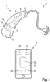
- a hearing device system 1 is shown schematically.
- This has a hearing device 2 (specifically in the form of a hearing aid) and a mobile terminal, here specifically in the form of a smartphone 4.
- the hearing device 2 has a signal processor 6 as a first controller and two microphones 8, a loudspeaker 10 and a (e.g. rechargeable) battery 12 as further electronic and electrical components.
- the hearing device 2 has a first narrowband communication device in the form of a Bluetooth Low Energy module (“BLE module 14") and a first ultra-wideband communication device (“UWB module 16”) as further components, which are also connected to the signal processor 6 for data transmission purposes.
- BLE module 14 Bluetooth Low Energy module
- UWB module 16 first ultra-wideband communication device
- the smartphone 4 has a controller 20, as a second narrowband communication device, a (second) BLE module 22, as a second
- Ultra-wideband communication device has a (second) UWB module 24 and a position detection system 26, which are interconnected with the controller 20 for data transmission purposes (not shown in detail).
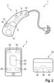
- FIG. 2 A further embodiment of the hearing device system 1 is shown.
- the hearing device system 1 also has a charger 30.
- the charger 30 has a third controller 32 and a (third) BLE module 34 as a third narrowband communication device and a (third) UWB module 36 as a third ultra-wideband communication device.
- the hearing device 2 is according to Fig. 2 without the UWB module 16 (and optionally without the BLE module 14).
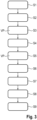
- Fig. 3 is a schematic representation of the hearing aid system 1 of the embodiment according to Fig. 1
- the signal processor 6 and the controller 20 of the smartphone 4 establish and maintain a narrowband connection using the respective BLE module 14 or 22 in a first method step S1.
- the controller 20 checks whether the narrowband connection between the hearing device 2 and the smartphone 4 (specifically between both BLE modules 14 or 22) still exists or whether it has been interrupted.
- the controller 20 of the smartphone 4 determines a current position in a third method step S3 using the position detection system 26 (e.g. satellite-based) and sets this as the lost position VP.
- the second controller 20 stores the lost position VP in a data memory (not shown) of the smartphone 4.
- the second controller 20 also issues a warning message, visually via a display 40 of the smartphone 4 and/or acoustically.
- a search mode This can occur automatically due to the absence of the hearing device 2 detected as described here or due to a user input.
- the user of the hearing device 2 if he himself notices its absence, can start the search mode in an application 42 installed on the smartphone 4.
- the second controller 20 first loads the loss position VP.
- the second controller 20 checks whether the smartphone 4 is within a predetermined distance value around the lost position VP. If this is not the case, the second controller 20 shows the user the lost position VP or at least a direction and distance to it so that the user can go there. If the smartphone 4 is within the predetermined distance value around the lost position, the second controller 20 sends a first trigger signal using the BLE module 22 in a seventh method step S7 in order to resume the narrowband connection with the hearing device 2. If the BLE module 14 of the hearing device 2 responds and thus resumes the narrowband connection, the second controller 20 uses the respective BLE signals, specifically their signal strength, to determine a distance value between the hearing device 2 and the smartphone 4 as a rough indication and also outputs this to the user.
- the second controller activates the UWB module 24 in an eighth method step S8 and sends a second trigger signal using the BLE module 22, which triggers the signal processor 6 of the hearing device 2 to activate the UWB module 16 of the hearing device 2.
- the signal processor 6 and the second controller 20 then establish a broadband connection with the UWB modules 16 and 24, respectively.
- the second controller 20 determines a distance value between the smartphone 4 and the hearing device 2 as well as a direction by means of a signal propagation time measurement of the UWB signals, for example by second controller 20 prompts the user to rotate or swivel the smartphone 4 around its own axis.
- the rotation position at which the smallest distance to the hearing device 2 is determined is used as a direction indication and the direction indication and the distance value are displayed to the user. Since the local resolution based on the signal runtime measurement is particularly precise, a particularly high probability is achieved that the user will find the hearing device 2 again.
- Fig. 2 In the case of Fig. 2 In the embodiment shown, this is done using Fig. 1 and 3
- the procedure described above also applies if the user has misplaced the charger 30.
- the charger 30, its third controller 32 and its BLE and UWB modules 34 and 36 then take the place of the hearing device 2, the signal processor 6 and the BLE and UWB modules 14 and 16 in an analogous manner.
- the position determination using the position detection system 26 can also be supported by additional measures, e.g. a recognized connection to a WLAN router or other devices. This can increase the spatial resolution within enclosed spaces in a manner known per se.
Landscapes
- Engineering & Computer Science (AREA)
- Computer Networks & Wireless Communication (AREA)
- Physics & Mathematics (AREA)
- Acoustics & Sound (AREA)
- Signal Processing (AREA)
- Health & Medical Sciences (AREA)
- General Health & Medical Sciences (AREA)
- Neurosurgery (AREA)
- Otolaryngology (AREA)
- Mobile Radio Communication Systems (AREA)
Applications Claiming Priority (1)
| Application Number | Priority Date | Filing Date | Title |
|---|---|---|---|
| DE102023204980.5A DE102023204980A1 (de) | 2023-05-26 | 2023-05-26 | Hörvorrichtungssystem |
Publications (1)
| Publication Number | Publication Date |
|---|---|
| EP4468746A1 true EP4468746A1 (fr) | 2024-11-27 |
Family
ID=91248999
Family Applications (1)
| Application Number | Title | Priority Date | Filing Date |
|---|---|---|---|
| EP24177530.3A Pending EP4468746A1 (fr) | 2023-05-26 | 2024-05-23 | Système de dispositif auditif |
Country Status (4)
| Country | Link |
|---|---|
| US (1) | US20240397270A1 (fr) |
| EP (1) | EP4468746A1 (fr) |
| CN (1) | CN119031314A (fr) |
| DE (1) | DE102023204980A1 (fr) |
Cited By (1)
| Publication number | Priority date | Publication date | Assignee | Title |
|---|---|---|---|---|
| US20240248163A1 (en) * | 2021-09-30 | 2024-07-25 | Huawei Technologies Co., Ltd. | Method for directing user and electronic device |
Citations (5)
| Publication number | Priority date | Publication date | Assignee | Title |
|---|---|---|---|---|
| US20180220241A1 (en) * | 2017-01-30 | 2018-08-02 | Sivantos Pte. Ltd. | Method for operating a hearing aid apparatus and hearing aid apparatus |
| US20190035256A1 (en) * | 2012-01-06 | 2019-01-31 | Iii Holdings 4, Llc | System and method for locating a hearing aid |
| CN212486738U (zh) * | 2020-03-11 | 2021-02-05 | 深圳市三嘉立信科技有限公司 | 一种追踪型无线耳机充电盒 |
| EP4152769A1 (fr) * | 2021-09-15 | 2023-03-22 | Sonova AG | Chargeur pour un dispositif auditif |
| US20230088534A1 (en) * | 2021-09-22 | 2023-03-23 | Jose Granados | Waterproof Hearing Aid |
Family Cites Families (2)
| Publication number | Priority date | Publication date | Assignee | Title |
|---|---|---|---|---|
| CN116097667A (zh) * | 2020-08-04 | 2023-05-09 | 三星电子株式会社 | 通过使用uwb和ar来搜索丢失装置的方法及其设备 |
| KR102564696B1 (ko) * | 2021-02-04 | 2023-08-08 | 주식회사 아모센스 | 무선 이어폰 |
-
2023
- 2023-05-26 DE DE102023204980.5A patent/DE102023204980A1/de active Pending
-
2024
- 2024-05-23 EP EP24177530.3A patent/EP4468746A1/fr active Pending
- 2024-05-24 CN CN202410652597.1A patent/CN119031314A/zh active Pending
- 2024-05-28 US US18/675,417 patent/US20240397270A1/en active Pending
Patent Citations (5)
| Publication number | Priority date | Publication date | Assignee | Title |
|---|---|---|---|---|
| US20190035256A1 (en) * | 2012-01-06 | 2019-01-31 | Iii Holdings 4, Llc | System and method for locating a hearing aid |
| US20180220241A1 (en) * | 2017-01-30 | 2018-08-02 | Sivantos Pte. Ltd. | Method for operating a hearing aid apparatus and hearing aid apparatus |
| CN212486738U (zh) * | 2020-03-11 | 2021-02-05 | 深圳市三嘉立信科技有限公司 | 一种追踪型无线耳机充电盒 |
| EP4152769A1 (fr) * | 2021-09-15 | 2023-03-22 | Sonova AG | Chargeur pour un dispositif auditif |
| US20230088534A1 (en) * | 2021-09-22 | 2023-03-23 | Jose Granados | Waterproof Hearing Aid |
Non-Patent Citations (1)
| Title |
|---|
| SCHOBER MICHAEL: "Implementation and Design of a UWB-Based Network Simulation Platform for Indoor Localization Systems", 30 April 2019 (2019-04-30), XP093214277, Retrieved from the Internet <URL:https://repository.tugraz.at/publications/8szgj-1v368> [retrieved on 20241010] * |
Cited By (1)
| Publication number | Priority date | Publication date | Assignee | Title |
|---|---|---|---|---|
| US20240248163A1 (en) * | 2021-09-30 | 2024-07-25 | Huawei Technologies Co., Ltd. | Method for directing user and electronic device |
Also Published As
| Publication number | Publication date |
|---|---|
| US20240397270A1 (en) | 2024-11-28 |
| CN119031314A (zh) | 2024-11-26 |
| DE102023204980A1 (de) | 2024-11-28 |
Similar Documents
| Publication | Publication Date | Title |
|---|---|---|
| EP2506603B1 (fr) | Système d'aide auditive avec système de microphone directif et procédé de fonctionnement dudit système d'aide auditive avec système de microphone directif | |
| EP2180726B2 (fr) | Localisation du son avec des prothèses auditives binauriculaires | |
| EP3451705B1 (fr) | Procédé et dispositif de reconnaissance rapide de voix propre | |
| DE102017201457B3 (de) | Verfahren zum Betreiben einer Hörhilfevorrichtung und Hörhilfevorrichtung | |
| EP1915031A2 (fr) | Système auditif doté d'une commande à distance servant de station de base et procédé de communication correspondant | |
| DE102013215131A1 (de) | Verfahren zur Verfolgung einer Schallquelle | |
| DE102014207311A1 (de) | Automatisches Auswählen von Hörsituationen | |
| EP4468746A1 (fr) | Système de dispositif auditif | |
| EP3116237B1 (fr) | Procédé d'exploitation d'un système d'appareil auditif et système d'appareil auditif | |
| EP2595414B1 (fr) | Dispositif auditif avec un système pour réduire un bruit de microphone et procédé de réduction d'un bruit de microphone | |
| EP3585071A1 (fr) | Procédé de commande de la transmission de données entre au moins un appareil auditif et un périphérique d'un système d'appareil auditif ainsi qu'appareil auditif | |
| DE102009021855A1 (de) | Verfahren zur Akklimatisierung einer programmierbaren Hörvorrichtung und zugehörige Hörvorrichtung | |
| DE112020006403T5 (de) | Nachverfolgung von drahtlosen peripherievorrichtungen | |
| EP2239963A1 (fr) | Procédé et dispositif auditif destinés au réglage d'un appareil auditif doté de dotées enregistrées dans une unité externe | |
| EP2373063A1 (fr) | Dispositif auditif et procédé de réglage de celui-ci pour un fonctionnement sans contre-réaction | |
| EP2822300A1 (fr) | Reconnaissance de situations d'écoute à l'aide de différentes sources de signal | |
| DE102019207680B3 (de) | Hörgerät, Receivereinheit sowie Verfahren zum Betrieb eines Hörgerätes | |
| EP2793488B1 (fr) | Adaptation de microphone binaurale au moyen de sa propre voix | |
| EP4149121A1 (fr) | Procédé de fonctionnement d'un appareil auditif | |
| DE102020201608B4 (de) | Verfahren zum automatischen Einstellen eines Parameters einer Signalverarbeitung eines Hörgerätes | |
| DE102019201879B3 (de) | Verfahren zum Betrieb eines Hörsystems und Hörsystem | |
| EP2590437B1 (fr) | Adaptation périodique d'un dispositif de suppression de l'effet Larsen | |
| DE102009024577A1 (de) | Verfahren zur Ermittlung einer Frequenzantwort einer Hörvorrichtung und zugehörige Hörvorrichtung | |
| EP3876555A1 (fr) | Procédé de transfert d'un ensemble de données de réglage de l'appareil auditif d'un premier appareil auditif à un second appareil auditif, système d'appareil auditif et appareil auditif | |
| DE102023204982A1 (de) | Betrieb einer Hörvorrichtung in einem Audiodarbietungssystem |
Legal Events
| Date | Code | Title | Description |
|---|---|---|---|
| PUAI | Public reference made under article 153(3) epc to a published international application that has entered the european phase |
Free format text: ORIGINAL CODE: 0009012 |
|
| STAA | Information on the status of an ep patent application or granted ep patent |
Free format text: STATUS: THE APPLICATION HAS BEEN PUBLISHED |
|
| AK | Designated contracting states |
Kind code of ref document: A1 Designated state(s): AL AT BE BG CH CY CZ DE DK EE ES FI FR GB GR HR HU IE IS IT LI LT LU LV MC ME MK MT NL NO PL PT RO RS SE SI SK SM TR |
|
| STAA | Information on the status of an ep patent application or granted ep patent |
Free format text: STATUS: REQUEST FOR EXAMINATION WAS MADE |
|
| 17P | Request for examination filed |
Effective date: 20250527 |