EP4470431A1 - Système de récipients - Google Patents
Système de récipients Download PDFInfo
- Publication number
- EP4470431A1 EP4470431A1 EP24156823.7A EP24156823A EP4470431A1 EP 4470431 A1 EP4470431 A1 EP 4470431A1 EP 24156823 A EP24156823 A EP 24156823A EP 4470431 A1 EP4470431 A1 EP 4470431A1
- Authority
- EP
- European Patent Office
- Prior art keywords
- container
- locking
- trigger
- lid
- sliding
- Prior art date
- Legal status (The legal status is an assumption and is not a legal conclusion. Google has not performed a legal analysis and makes no representation as to the accuracy of the status listed.)
- Pending
Links
- 230000007246 mechanism Effects 0.000 claims abstract description 80
- 239000011521 glass Substances 0.000 claims description 8
- 235000013305 food Nutrition 0.000 claims description 6
- XEEYBQQBJWHFJM-UHFFFAOYSA-N Iron Chemical compound [Fe] XEEYBQQBJWHFJM-UHFFFAOYSA-N 0.000 claims description 4
- 240000007594 Oryza sativa Species 0.000 claims description 2
- 235000007164 Oryza sativa Nutrition 0.000 claims description 2
- 238000010438 heat treatment Methods 0.000 claims description 2
- 229910052742 iron Inorganic materials 0.000 claims description 2
- 239000008267 milk Substances 0.000 claims description 2
- 210000004080 milk Anatomy 0.000 claims description 2
- 235000013336 milk Nutrition 0.000 claims description 2
- 235000009566 rice Nutrition 0.000 claims description 2
- 235000012773 waffles Nutrition 0.000 claims description 2
- 238000013461 design Methods 0.000 description 7
- 230000001960 triggered effect Effects 0.000 description 5
- 230000006378 damage Effects 0.000 description 4
- 239000000463 material Substances 0.000 description 3
- 238000012544 monitoring process Methods 0.000 description 3
- 208000027418 Wounds and injury Diseases 0.000 description 2
- 238000004140 cleaning Methods 0.000 description 2
- 208000014674 injury Diseases 0.000 description 2
- 238000003780 insertion Methods 0.000 description 2
- 230000037431 insertion Effects 0.000 description 2
- 239000002184 metal Substances 0.000 description 2
- 229910052751 metal Inorganic materials 0.000 description 2
- 230000008878 coupling Effects 0.000 description 1
- 238000010168 coupling process Methods 0.000 description 1
- 238000005859 coupling reaction Methods 0.000 description 1
- 230000001419 dependent effect Effects 0.000 description 1
- 238000011161 development Methods 0.000 description 1
- 230000018109 developmental process Effects 0.000 description 1
- 238000006073 displacement reaction Methods 0.000 description 1
- 238000011022 operating instruction Methods 0.000 description 1
- 238000012545 processing Methods 0.000 description 1
- XLYOFNOQVPJJNP-UHFFFAOYSA-N water Substances O XLYOFNOQVPJJNP-UHFFFAOYSA-N 0.000 description 1
Images


Classifications
-
- A—HUMAN NECESSITIES
- A47—FURNITURE; DOMESTIC ARTICLES OR APPLIANCES; COFFEE MILLS; SPICE MILLS; SUCTION CLEANERS IN GENERAL
- A47J—KITCHEN EQUIPMENT; COFFEE MILLS; SPICE MILLS; APPARATUS FOR MAKING BEVERAGES
- A47J43/00—Implements for preparing or holding food, not provided for in other groups of this subclass
- A47J43/04—Machines for domestic use not covered elsewhere, e.g. for grinding, mixing, stirring, kneading, emulsifying, whipping or beating foodstuffs, e.g. power-driven
- A47J43/07—Parts or details, e.g. mixing tools, whipping tools
- A47J43/075—Safety devices
- A47J43/0761—Safety devices for machines with tools driven from the lower side
- A47J43/0772—Safety devices for machines with tools driven from the lower side activated by the proper positioning of the cover
- A47J43/0777—Safety devices for machines with tools driven from the lower side activated by the proper positioning of the cover in which the activating element on the cover transmits a signal to a safety device in the base element via the mixing bowl removably seated on this base element, e.g. pin on the cover moves a pushrod in the bowl handle to operate safety switch in the base element
-
- A—HUMAN NECESSITIES
- A47—FURNITURE; DOMESTIC ARTICLES OR APPLIANCES; COFFEE MILLS; SPICE MILLS; SUCTION CLEANERS IN GENERAL
- A47J—KITCHEN EQUIPMENT; COFFEE MILLS; SPICE MILLS; APPARATUS FOR MAKING BEVERAGES
- A47J43/00—Implements for preparing or holding food, not provided for in other groups of this subclass
- A47J43/04—Machines for domestic use not covered elsewhere, e.g. for grinding, mixing, stirring, kneading, emulsifying, whipping or beating foodstuffs, e.g. power-driven
- A47J43/07—Parts or details, e.g. mixing tools, whipping tools
- A47J43/0727—Mixing bowls
Definitions
- the present invention relates to a container system comprising a container and a lid for closing the container.
- the container system comprises at least one electrically operable device, a first locking mechanism for locking the lid to the container at at least one first locking point and a second locking mechanism for locking the lid to the container at at least one second locking point that is different from the at least one first locking point.
- the lid also comprises a sliding mechanism with a sliding element that has a trigger element for triggering a release of the at least one electrically operable device and a receiving area for receiving an upper part of the container.
- the container system according to the invention has increased safety. In particular, the risk of goods in the container escaping during operation of the at least one electrically operable device can be substantially avoided or at least significantly reduced.
- Container systems in which the lid is only attached to the container via the lid seal and which are therefore completely unsecured are essentially no longer found in Europe.
- Container systems with a circumferential closure can also be found.
- a secure lid closure is usually implemented using a so-called bayonet closure.
- the rotating movement causes different segments to overlap, creating a good, secure mechanical connection.
- the container is preferably made of plastic here, as this can be implemented without great effort.
- Glass containers could also be designed with corresponding segments, but this is much more complex to implement and therefore very expensive.
- plastic systems significantly limit the design requirements. The effort required for cleaning is increased, and the durability of the material due to the hardening of the plastic is significantly worse, especially when used in the dishwasher. Likewise, with premium products, a plastic container is not the requirement in terms of food safety. Glass, on the other hand, meets these requirements.
- the locks or safety devices of existing container systems cannot prevent the lid from being opened or lifted on one side.
- the lid can still be lifted on one side.
- the one-sided safety device is activated and the lid is not opened further than a finger or hand can get into the opening, the system is considered safe according to the currently valid legal safety requirements.
- this cannot prevent food from being thrown out of the container or suddenly escaping before the safety device is activated.
- the lid can be opened "a finger's width" without the one-sided safety device being activated.
- the device can be put into operation without the area of the lid opposite the one-sided safety system being properly closed. This is particularly true for systems with lid systems that overlap the container spout: The device can be put into operation without the lid system overlapping the spout. This is all the more dangerous because the customer feels a false sense of security.
- the one-sided safety device cannot prevent extreme cases, so there is an increased risk of damage to property and personal injury. This can also be found in the warnings in the device's operating instructions, especially when processing heated foods.
- the object of the present invention was to provide a container system comprising a container, a lid for closing the container and at least one electrically operable device, in which a correct placement of the lid is possible in a simple manner and which has increased safety.
- the first locking mechanism comprises at least one first locking element located on the lid, which can be brought into engagement with at least one first counter-element located on the container at the at least one first locking point in order to lock the lid to the container.
- the second locking mechanism comprises at least one second locking element located on the lid, which can be brought into engagement with at least one second counter-element located on the container at the at least one second locking point in order to lock the lid to the container.
- the lid comprises a sliding mechanism with a sliding element, which has a trigger element for triggering a release of the at least one electrically operable device and a receiving area for receiving an upper part of the container.
- the at least one first locking point is understood to mean the at least one point of the container system at which the at least one first locking element is (or is) in engagement with the at least one first counter element when the lid is locked to the container via the at least one first locking mechanism.
- the at least one second locking point is understood to mean the at least one point of the container system at which the at least one second locking element is (or is) in engagement with the at least one second counter element when the lid is locked to the container via the at least one second locking mechanism.
- the container system according to the invention has two locking mechanisms by which the lid is locked to the container at different locking points. This alone means that the container system has increased security compared to known container systems with only one locking mechanism.
- the container system according to the invention is therefore very user-friendly.
- the coordinated function of the sliding mechanism with the first and second locking mechanism means that the lid can be placed correctly on the container in a simple manner, whereby the lid is (inevitably) locked to the container via both locking mechanisms. Incorrectly placing the lid on, however, is significantly more difficult and is also easily recognizable by the fact that the electrically operated device cannot be put into operation.
- the safety of the container system according to the invention is also increased by the fact that the trigger element is positioned relative to the at least one first locking element in such a way that the trigger element cannot be brought into the trigger position at the trigger point of the container when the sliding element is in the basic position.
- the container system according to the invention has significantly increased safety, both with regard to possible personal injuries and with regard to possible material damage caused by the escape of goods from the container during operation of the at least one electrically operated device.
- the risk of a sudden opening of the lid during operation of the at least one electrically operated device can also be more easily avoided or significantly reduced.
- a further advantage of the container system according to the invention is that the first locking mechanism, the second locking mechanism and also the sliding mechanism can be designed purely mechanically. This does not pose any additional risk of, for example, electrical short circuits or similar due to dirt and water. No additional current-carrying devices are required either.
- An essential element of the container system according to the invention is the special sliding mechanism.
- This has a sliding element which, on the one hand, has a trigger element for triggering a release of the at least one electrically operable device and, on the other hand, has a receiving area for receiving an upper part of the container, preferably comprising the entire circumference of the container at the upper end of the container.
- the sliding element can be moved from a basic position to a displaced position in a direction parallel to a base area of the lid by locking the second locking mechanism.
- the sliding element can thus assume a basic position or a displaced position, wherein the sliding element can be moved from the basic position to the displaced position by locking the second locking mechanism.
- the movement from the basic position to the displaced position takes place in a direction parallel to a base area of the lid.
- the base area is understood to be the main extension plane of the lid.
- the displacement of the sliding element in a direction parallel to a base surface (or main extension plane) of the lid from a basic position into a displaced position is achieved by bringing the at least one second locking element into engagement with the at least one second counter element.
- the sliding element is displaced from the basic position into the displaced position by bringing the at least one second locking element into engagement with the at least one second counter element in a direction parallel to a base surface (or main extension plane) of the lid.
- the position of the sliding element is of crucial importance for triggering the release of the at least one electrically operable device by the triggering element.
- the triggering element is positioned relative to the at least one first locking element in such a way that when (or by) the upper part of the container is received in the receiving area, both the at least one first locking element is brought into engagement with the at least one first counter element and the triggering element is brought into a triggering position at a triggering point of the container, in which it triggers a release of the at least one electrically operable device.
- the triggering element When the sliding element is in the basic position, the triggering element, on the other hand, is positioned relative to the at least one first locking element in such a way that the triggering element cannot be brought into the triggering position at the triggering point of the container (when attempting to receive the upper part of the container in the receiving area). This ensures that the release of the at least one electrically operable device cannot occur when the sliding element is in the home position. Instead, the sliding element must be moved (by engaging the at least one second locking element with the at least one second counter element in the moved position) so that the release of the at least one electrically operable device can be triggered.
- the sliding element is moved from the home position to the moved position by engaging the at least one second locking element with the at least one second counter element, the risk of the release of the at least one electrically operable device being triggered when the at least one second locking element is not engaged with the at least one second counter element can be substantially avoided or at least significantly reduced.
- both the at least one first locking element is brought into engagement with the at least one first counter element and the trigger element is brought into a trigger position at a trigger point of the container, and in addition, when the sliding element is in the basic position, the trigger element is positioned relative to the at least one first locking element such that the trigger element (when attempting to receive the upper part of the container in the receiving area) cannot be brought into the trigger position at the trigger point of the container, it is ensured that the release of the at least one electrically operable device is only triggered when the at least one first locking element is brought into engagement with the at least one first counter element.
- the risk that the release of the at least one electrically operated device is triggered or that the at least one electrically operated device can be activated unless both the at least one first locking element is engaged with the at least one first counter element and the at least one second locking element is engaged with the at least one second counter element can be essentially avoided or at least significantly reduced.
- the risk of operating the device when the lid is not correctly placed on the container or when both locking mechanisms are not fully locked can thus be further minimized.
- the risk of goods in the container escaping during operation of the at least one electrically operated device can be further reduced or essentially avoided.
- the triggering element can thus only be inserted into the second recess and brought into the triggering position at the triggering point of the container when the sliding element is in the displaced position, since the first locking element can then be inserted into the first recess at the same time.
- the distance between the trigger element and the first locking element is too small to insert them into the respective recesses.
- the trigger element cannot be inserted into the second recess because the first locking element cannot be inserted into the first recess and thus blocks the insertion of the trigger element into the second recess.
- a further preferred embodiment of the container system according to the invention is characterized in that the at least one second locking element is designed in the form of at least one undercut on the edge of the lid and the at least one second counter element is at least one protruding section of the upper part of the container, preferably a spout arranged on the container or a part of a spout arranged on the container.
- the at least one second locking element comprises a plurality of second locking elements and/or the at least one second counter element comprises a plurality of second counter elements.
- a further preferred embodiment of the container system according to the invention is characterized in that the sliding mechanism has a spring element which is in a relaxed state when the sliding element is in the basic position and which is in a tensioned state when the sliding element is in the displaced position.
- the spring element is designed in such a way that when the sliding element is moved from the basic position to the displaced position (by engaging the second locking element with the second counter element), it is transferred from the relaxed state to the tensioned state and that when it changes from the tensioned state to the relaxed state, it moves the sliding element (from the displaced position) to the basic position.
- the spring element thus automatically causes the sliding element to move back (from the displaced position) to the basic position when the second locking element is removed from engagement with the second counter element.
- the container has a band element, preferably a metal band, which extends from the trigger point of the container to the at least one electrically operable device and is displaced, preferably pressed downwards, by bringing the trigger element into the trigger position at the trigger point, whereby it releases a safety element, e.g. a safety switch, in the at least one electrically operable device so that it can be operated electrically.
- a safety element e.g. a safety switch
- the trigger element can trigger the release of the at least one electrically operable device when it is brought into the trigger position at the trigger point of the container.
- a further preferred embodiment of the container system according to the invention is characterized in that the sliding element has a lever device which comprises a rotating mechanism by means of which the trigger element is rotated when the sliding element is moved from the basic position to the moved position (or is rotated into an active position from which it can be brought into the trigger position), wherein when the sliding element is in the basic position, the trigger element is recessed in a recess in a base body of the lid.
- the trigger element is rotated by the rotation mechanism when the sliding element is moved from the basic position to the moved position by an angle of 10° to 170°, particularly preferably by an angle of 45° to 135°, very particularly preferably by an angle of 80° to 100°, for example by 90°.
- the sliding element has an attachment element on a side facing the at least one second locking element, to which the at least one second counter element can be attached, wherein the attachment element is arranged next to the at least one second locking element in the basic position of the sliding element in such a way that by pressing the at least one second counter element attached to the attachment element against the attachment element, the at least second locking element can be brought into engagement with the at least second counter element.
- a glass container By using a glass container, higher design demands can be met. In addition, the effort required for cleaning is significantly lower and the durability of the material is significantly higher than with plastic, especially when used in the dishwasher. Furthermore, a glass container meets high demands in terms of food safety.
- a further preferred embodiment of the container system according to the invention is characterized in that the container system is a mixer, in particular a stand mixer; a combination of mixing bowl and lid, in particular for a food processor; an electric chopper; a kettle; a coffee machine, in particular a brewing coffee machine; a grinding device, in particular a coffee grinder; a rice cooker; a steamer; a milk frother; an egg cooker; a sandwich maker; a grill device, in particular a contact grill; a waffle iron; a deep fryer; or a pressure cooker.
- the container system is a mixer, in particular a stand mixer; a combination of mixing bowl and lid, in particular for a food processor; an electric chopper; a kettle; a coffee machine, in particular a brewing coffee machine; a grinding device, in particular a coffee grinder; a rice cooker; a steamer; a milk frother; an egg cooker; a sandwich maker; a grill device, in particular a contact grill; a waffle iron;
- a further preferred embodiment of the container system according to the invention is characterized in that only when the at least one second locking element is engaged with the at least one second counter element (and the sliding element is therefore in the displaced position), the trigger element is positioned relative to the at least one first locking element such that when the upper part of the container is received in the receiving area, both the at least one first locking element can be brought into engagement with the at least one first counter element and the trigger element can be brought into a trigger position at a trigger point of the container, in which it triggers a release of the at least one electrically operable device.
- a particularly preferred embodiment of the container system according to the invention is characterized in that the trigger element can only be in the trigger position at the trigger point of the container in which it enables the release of the at least one electrically operable device triggers when both the at least one first locking element is engaged with the at least one first counter element and the at least one second locking element is engaged with the at least one second counter element.
- additional locking positions could preferably be checked by coupling the sliding mechanism accordingly.
- This design could also be used as a safety check for lid closures with bayonet closures, e.g. as a check on the pouring spout or another raised area on the glass container. The same raised area that is used for the bayonet mechanism could also be used.
- a hook device is available. It can also be combined with a known locking mechanism with an opening button, an actuating button with a sliding or lifting mechanism or other linear or rotating locking mechanisms.
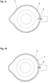
- FIG. 1a to 1d various representations of a first exemplary embodiment of the container system according to the invention are shown.
- the container system is shown in the closed state, where Fig. 1a a side view and Fig. 1c shows a top view.
- Fig. 1b and 1d the container system is shown in the open or non-closed state, whereby Fig. 1b a side view and Fig. 1d shows a top view.
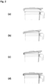
- Fig. 2 the correct placement of the lid on the container of this first exemplary embodiment of the container system according to the invention is illustrated. For reasons of clarity, Fig. 2 on the Representation of the reference symbols is omitted.
- the container system comprises a container 1, e.g. a glass container, and a lid 2 for closing the container 1.
- the container system further comprises an electrically operable device (not shown in the figures), e.g. a motor, a first locking mechanism for locking the lid 2 to the container 1 at a first locking point and a second locking mechanism for locking the lid 2 to the container 1 at a second locking point different from the first locking point.
- the first locking mechanism is a hook mechanism.
- the first locking mechanism comprises a first locking element 3 in the form of a hook located on the lid 2, which can be brought into engagement with a first counter element 4 located on the container 1 in order to lock the lid 2 to the container 1 at the first locking point.
- the container also has a handle 10, which is arranged on the same side of the container system as the first locking element 3 and the first counter element 4.
- the first counter element 4 is arranged on the handle 10.
- the second locking mechanism comprises a second locking element 5 located on the lid 2, which can be brought into engagement with a second counter element 6 located on the container 1 at the second locking point in order to lock the lid 2 to the container 1.
- the second locking element 5 is designed in the form of an undercut on the edge of the lid 2.
- the second counter element 6 is a spout arranged on the container 1 or a part of this spout.
- Fig. 1b which shows the container system in the closed state
- both the first locking element 3 is or is in engagement with the first counter element 4
- the second locking element 5 is or is in engagement with the second counter element 6, ie the lid is here both via the first locking mechanism at the first locking point and via the second locking mechanism at the second locking point with the container.
- the first locking point is located on a first side of the container system and the second locking point is located on a second side of the container system opposite the first side of the container system.
- the lid 2 further comprises a sliding mechanism with a sliding element 7, which has a trigger element 8 for triggering a release of the electrically operable device and a receiving area for receiving an upper part of the container 1.
- the trigger element 8 is designed in the form of a pin and is arranged on a side of the receiving area facing the first locking element 3.
- the sliding element 7 can be moved from a basic position to a displaced position by engaging the second locking element 5 with the second counter element 8 in a direction parallel to a base surface of the lid 2. In Fig. 1a and 1c the sliding element is in the shifted position, whereas in Fig. 1b and 1d is in the basic position.
- the sliding element 7 has an attachment element 12 on a side facing the second locking element 5, to which the second counter element 6 can be attached.
- the attachment element 12 is arranged next to the second locking element 5 in such a way that by pressing the second counter element 6 attached to the attachment element 12 against the attachment element 12, the second locking element 5 is brought into engagement with the second counter element 6.
- the sliding mechanism has a spring element 9, which is in a relaxed state when the sliding element 7 is in the basic position, and which is in a tensioned state when the sliding element 7 is in the displaced position.
- the spring element 9 is designed in such a way that when the sliding element 7 is displaced from the basic position to the displaced position - by engaging the second locking element 5 with the second counter element 6 - it is transferred from the relaxed state to the tensioned state and that when it changes from the tensioned state to the relaxed state state, the sliding element 7 moves (from the displaced position) into the basic position.
- the spring element 9 thus automatically moves the sliding element 7b back (from the displaced position) into the basic position when the second locking element 5 is removed from engagement with the second counter element 6.
- FIG. 2 The correct placement of the lid on the container of the first exemplary embodiment of the container system according to the invention is illustrated.
- illustration (a) of the Fig. 2 The container system is shown in the open or non-closed state. This representation corresponds to that in Fig. 1b .
- the second counter element 6 is now first attached to the attachment element 12, as shown in illustration (b) of the Fig. 2 is shown. Then, by pressing the second counter element 6 attached to the attachment element 12 against the attachment element 12, the second locking element 5 is brought into engagement with the second counter element 6, whereby the sliding element 7 is simultaneously moved in a direction parallel to the base surface of the lid 2 from the basic position to the displaced position and the spring element 9 is transferred from the relaxed state to the tensioned state.
- the trigger element 8 is positioned relative to the first locking element 3 such that when the upper part of the container 1 is received in the receiving area both the first locking element 3 is brought into engagement with the first counter element 4 and the trigger element 8 is brought into the trigger position at the trigger point of the container 1, in which it triggers a release of the at least one electrically operable device. If, however, the sliding element 7 is in the basic position, as in the illustrations (a) and (b) of the Fig.
- the trigger element 8 is positioned relative to the first locking element 3 in such a way that neither the trigger element 8 can be brought into the trigger position at the trigger point of the container 1, nor can the first locking element 3 be brought into engagement with the first counter element 4.
- the trigger element 8 and the at least one first locking element 3 are at a greater distance from one another when the sliding element 7 is in the displaced position than when the sliding element 7 is in the basic position.
- the first locking element 3 protrudes further from a base body of the lid 2 than the trigger element 8 in a direction perpendicular to the base area of the lid 2.
- the container 1 also has a first recess for the first locking element and a second recess for the trigger element.
- the first locking element 3 is inserted into the first recess when the first locking element 3 is brought into engagement with the first counter element 4.
- the trigger element 8 is inserted into the second recess when the trigger element 8 is brought into the trigger position at the trigger point of the container 1.
- the trigger element 8 and the first locking element 3 are spaced apart by a distance that corresponds to the distance between the first recess and the second recess, whereas when the sliding element 7 is in the basic position, the trigger element 8 and the first locking element 3 are spaced apart by a distance that is smaller than the distance between the first recess and the second recess.
- the trigger element 8 can only be inserted into the second recess and brought into the trigger position at the trigger point of the container 1 when the sliding element 7 is in the displaced position, since the first locking element 3 can then be inserted into the first recess at the same time.
- the distance between the trigger element 8 and the first locking element 3 is too small to insert them into the respective recesses.
- the trigger element 8 cannot be inserted into the second recess because the first locking element 3 cannot be inserted into the first recess and thus blocks the insertion of the trigger element 8 into the second recess.
- the container 1 further comprises a band element 13, e.g. a metal band, which extends from the trigger point of the container 1 to the electrically operable device and is pressed downwards by bringing the trigger element 8 into the trigger position at the trigger point, thereby releasing a safety switch in the electrically operable device so that it can be operated electrically.
- the trigger element 8 can trigger the release of the electrically operable device when it is brought into the trigger position at the trigger point of the container.
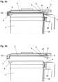
- FIG. 3a to 3d show various representations of a second exemplary embodiment of the container system according to the invention.
- the container system is shown in the closed state, where Fig. 3a a side view and Fig. 3c shows a top view.
- Fig. 3b and 3d the container system is shown in the open and non-closed state, respectively, where Fig. 3b a side view and Fig. 3d a top view.
- Fig. 4 the correct placement of the lid on the container of this second exemplary embodiment of the container system according to the invention.
- Fig. 4 the representation of reference symbols is omitted.
- the container system according to the second exemplary embodiment differs from the container system according to the first exemplary embodiment in that the sliding element 7 has a lever device 11 which comprises a rotation mechanism by which the trigger element 8 is rotated by 90° when the sliding element 7 is moved from the basic position to the moved position, wherein, when the sliding element 7 is in the basic position, the trigger element 8 is sunk into a recess located in a base body of the lid 2.
- the sliding element 7 has a lever device 11 which comprises a rotation mechanism by which the trigger element 8 is rotated by 90° when the sliding element 7 is moved from the basic position to the moved position, wherein, when the sliding element 7 is in the basic position, the trigger element 8 is sunk into a recess located in a base body of the lid 2.
- the operation of the container system according to the second exemplary embodiment corresponds to that of the container system according to the first exemplary embodiment, wherein the reference numerals correspond to the same elements.
- FIG. 4 The correct placement of the lid on the container of the second exemplary embodiment of the container system according to the invention is illustrated.
- the container system is shown in the open or non-closed state. This representation corresponds to that in Fig. 3b
- the release element 8 is recessed in a recess in the base body of the cover 2.
- the second counter element 6 is first attached to the attachment element 12, as shown in illustration (b) of the Fig. 4 is shown.
- the upper part of the container 1 can then be received in the receiving area, whereby both the at least one first locking element 3 is brought into engagement with the at least one first counter element 4 and the trigger element 9 is brought into a trigger position at a trigger point of the container 1, in which it triggers a release of the at least one electrically operable device.
- the container system is now in the closed state, as shown in illustration (d) of the Fig. 4 This representation corresponds to that in Fig. 3a .
Landscapes
- Engineering & Computer Science (AREA)
- Mechanical Engineering (AREA)
- Food Science & Technology (AREA)
- Closures For Containers (AREA)
Applications Claiming Priority (1)
| Application Number | Priority Date | Filing Date | Title |
|---|---|---|---|
| DE102023205031.5A DE102023205031A1 (de) | 2023-05-30 | 2023-05-30 | Behältersystem |
Publications (1)
| Publication Number | Publication Date |
|---|---|
| EP4470431A1 true EP4470431A1 (fr) | 2024-12-04 |
Family
ID=89900720
Family Applications (1)
| Application Number | Title | Priority Date | Filing Date |
|---|---|---|---|
| EP24156823.7A Pending EP4470431A1 (fr) | 2023-05-30 | 2024-02-09 | Système de récipients |
Country Status (2)
| Country | Link |
|---|---|
| EP (1) | EP4470431A1 (fr) |
| DE (1) | DE102023205031A1 (fr) |
Citations (4)
| Publication number | Priority date | Publication date | Assignee | Title |
|---|---|---|---|---|
| EP0063241A1 (fr) * | 1981-04-03 | 1982-10-27 | Braun Aktiengesellschaft | Dispositif d'entraînement à moteur électrique pour robots de cuisine |
| DE4414822A1 (de) * | 1994-04-28 | 1995-11-02 | Vorwerk Co Interholding | Küchenmaschine |
| US20140217216A1 (en) * | 2010-07-27 | 2014-08-07 | Euro-Pro Operating Llc | Food processor with attachment |
| EP3245923B1 (fr) * | 2016-05-18 | 2020-04-22 | Home Culture Appliance (Shenzhen) Limited | Dispositif à couvercle d'un robot de cuisine |
Family Cites Families (6)
| Publication number | Priority date | Publication date | Assignee | Title |
|---|---|---|---|---|
| FR2874806B1 (fr) * | 2004-09-09 | 2006-12-01 | Seb Sa | Appareil de cuisson sous pression a securite amelioree |
| FR2953390B1 (fr) * | 2009-12-03 | 2012-01-06 | Seb Sa | Appareil electromenager de preparation culinaire comportant un recipient de travail comprenant une resistance electrique |
| DE102011052745A1 (de) * | 2011-08-16 | 2013-02-21 | Vorwerk & Co. Interholding Gmbh | Elektrisch betriebene Küchenmaschine |
| DE102013206000A1 (de) * | 2013-04-04 | 2014-10-09 | Gero Vertriebs-Gmbh | Kochtopf |
| DE102014115787A1 (de) * | 2014-10-30 | 2016-05-04 | Vorwerk & Co. Interholding Gmbh | Küchenmaschine mit Verriegelungseinrichtung |
| FR3082717B1 (fr) * | 2018-06-26 | 2020-07-03 | Seb S.A. | Autocuiseur muni d'une butee pour couvercle |
-
2023
- 2023-05-30 DE DE102023205031.5A patent/DE102023205031A1/de active Pending
-
2024
- 2024-02-09 EP EP24156823.7A patent/EP4470431A1/fr active Pending
Patent Citations (4)
| Publication number | Priority date | Publication date | Assignee | Title |
|---|---|---|---|---|
| EP0063241A1 (fr) * | 1981-04-03 | 1982-10-27 | Braun Aktiengesellschaft | Dispositif d'entraînement à moteur électrique pour robots de cuisine |
| DE4414822A1 (de) * | 1994-04-28 | 1995-11-02 | Vorwerk Co Interholding | Küchenmaschine |
| US20140217216A1 (en) * | 2010-07-27 | 2014-08-07 | Euro-Pro Operating Llc | Food processor with attachment |
| EP3245923B1 (fr) * | 2016-05-18 | 2020-04-22 | Home Culture Appliance (Shenzhen) Limited | Dispositif à couvercle d'un robot de cuisine |
Also Published As
| Publication number | Publication date |
|---|---|
| DE102023205031A1 (de) | 2024-12-05 |
Similar Documents
| Publication | Publication Date | Title |
|---|---|---|
| DE69707300T2 (de) | Haushaltsgerät mit rotierendem messer zur zubereitung von lebensmitteln versehen mit sicherheitsvorrichtung | |
| DE2945000C2 (fr) | ||
| EP2484250B1 (fr) | Couvercle doté d'un dispositif de verrouillage | |
| EP3875003B1 (fr) | Récipient de préparation doté d'un dispositif de verrouillage | |
| EP4233653B1 (fr) | Récipient de préparation pour une base de robot de cuisine et robot de cuisine | |
| EP1875022A1 (fr) | Appareil menager comprenant un dispositif de verrouillage | |
| DE602005003281T2 (de) | Druckkochgerät mit verbesserter Sicherheit | |
| DE2900987A1 (de) | Sicherungsanordnung fuer verriegelungshebel fuer den becher von mixgeraeten, insbesondere kochmixgeraeten | |
| DE4040489C2 (fr) | ||
| DE3540370A1 (de) | Sicherheitsvorrichtung fuer kuechengeraete | |
| DE102023205031A1 (de) | Behältersystem | |
| DE60003394T2 (de) | Elektrisches gerät des typs waffeleisen mit automatischer öffnung | |
| DE19960267A1 (de) | Gerät zum Schneiden von Lebensmittelprodukten mit einer Sicherheitseinrichtung gegen ein versehentliches Einschalten | |
| EP3880049B1 (fr) | Récipient à fixation de poignée pouvant être universellement insérée destiné à l'utilisation avec des appareils électroménagers | |
| EP1269898B1 (fr) | Appareil menager | |
| EP3754680B1 (fr) | Dispositif de commutation pour un appareil de cuisson doté d'un espace de cuisson pouvant être fermé par une porte et appareil de cuisson | |
| DE3837961C2 (de) | Küchenmaschine mit aufsetzbarem Elektro-Handquirl als Antrieb | |
| EP3287057B1 (fr) | Dispositif de verrouillage destinée à contenir une unité de traitement | |
| EP3273164A2 (fr) | Appareil de cuisson comprenant un dispositif de verrouillage | |
| EP3771386B1 (fr) | Robot de cuisine à système de verrouillage | |
| DE3027064C2 (fr) | ||
| EP4137019A1 (fr) | Base de robot de cuisine, module de préparation et robot de cuisine | |
| EP4643733A1 (fr) | Module de préparation pour un appareil de cuisine, boîtier et appareil de cuisine | |
| EP3771380A1 (fr) | Fermeture de sécurité pour la cuve d'une machine de cuisine, cuve avec fermeture de sécurité et machine de cuisine | |
| EP3910245B1 (fr) | Plaque de cuisson avec un dispositif de réception pour un robot ménager |
Legal Events
| Date | Code | Title | Description |
|---|---|---|---|
| PUAI | Public reference made under article 153(3) epc to a published international application that has entered the european phase |
Free format text: ORIGINAL CODE: 0009012 |
|
| STAA | Information on the status of an ep patent application or granted ep patent |
Free format text: STATUS: REQUEST FOR EXAMINATION WAS MADE |
|
| 17P | Request for examination filed |
Effective date: 20240209 |
|
| AK | Designated contracting states |
Kind code of ref document: A1 Designated state(s): AL AT BE BG CH CY CZ DE DK EE ES FI FR GB GR HR HU IE IS IT LI LT LU LV MC ME MK MT NL NO PL PT RO RS SE SI SK SM TR |