EP4470458A1 - Elektrodenentladung an einer messvorrichtung - Google Patents
Elektrodenentladung an einer messvorrichtung Download PDFInfo
- Publication number
- EP4470458A1 EP4470458A1 EP23176230.3A EP23176230A EP4470458A1 EP 4470458 A1 EP4470458 A1 EP 4470458A1 EP 23176230 A EP23176230 A EP 23176230A EP 4470458 A1 EP4470458 A1 EP 4470458A1
- Authority
- EP
- European Patent Office
- Prior art keywords
- measurement
- electrode
- discharging
- circuit
- electrodes
- Prior art date
- Legal status (The legal status is an assumption and is not a legal conclusion. Google has not performed a legal analysis and makes no representation as to the accuracy of the status listed.)
- Pending
Links
Images



Classifications
-
- A—HUMAN NECESSITIES
- A61—MEDICAL OR VETERINARY SCIENCE; HYGIENE
- A61B—DIAGNOSIS; SURGERY; IDENTIFICATION
- A61B5/00—Measuring for diagnostic purposes; Identification of persons
- A61B5/05—Detecting, measuring or recording for diagnosis by means of electric currents or magnetic fields; Measuring using microwaves or radio waves
- A61B5/053—Measuring electrical impedance or conductance of a portion of the body
- A61B5/0531—Measuring skin impedance
- A61B5/0533—Measuring galvanic skin response
-
- A—HUMAN NECESSITIES
- A61—MEDICAL OR VETERINARY SCIENCE; HYGIENE
- A61B—DIAGNOSIS; SURGERY; IDENTIFICATION
- A61B5/00—Measuring for diagnostic purposes; Identification of persons
- A61B5/05—Detecting, measuring or recording for diagnosis by means of electric currents or magnetic fields; Measuring using microwaves or radio waves
- A61B5/053—Measuring electrical impedance or conductance of a portion of the body
- A61B5/0537—Measuring body composition by impedance, e.g. tissue hydration or fat content
-
- A—HUMAN NECESSITIES
- A61—MEDICAL OR VETERINARY SCIENCE; HYGIENE
- A61B—DIAGNOSIS; SURGERY; IDENTIFICATION
- A61B5/00—Measuring for diagnostic purposes; Identification of persons
- A61B5/24—Detecting, measuring or recording bioelectric or biomagnetic signals of the body or parts thereof
- A61B5/30—Input circuits therefor
- A61B5/307—Input circuits therefor specially adapted for particular uses
- A61B5/308—Input circuits therefor specially adapted for particular uses for electrocardiography [ECG]
-
- A—HUMAN NECESSITIES
- A61—MEDICAL OR VETERINARY SCIENCE; HYGIENE
- A61B—DIAGNOSIS; SURGERY; IDENTIFICATION
- A61B5/00—Measuring for diagnostic purposes; Identification of persons
- A61B5/24—Detecting, measuring or recording bioelectric or biomagnetic signals of the body or parts thereof
- A61B5/316—Modalities, i.e. specific diagnostic methods
- A61B5/318—Heart-related electrical modalities, e.g. electrocardiography [ECG]
-
- A—HUMAN NECESSITIES
- A61—MEDICAL OR VETERINARY SCIENCE; HYGIENE
- A61B—DIAGNOSIS; SURGERY; IDENTIFICATION
- A61B5/00—Measuring for diagnostic purposes; Identification of persons
- A61B5/68—Arrangements of detecting, measuring or recording means, e.g. sensors, in relation to patient
- A61B5/6801—Arrangements of detecting, measuring or recording means, e.g. sensors, in relation to patient specially adapted to be attached to or worn on the body surface
- A61B5/6813—Specially adapted to be attached to a specific body part
- A61B5/6829—Foot or ankle
-
- A—HUMAN NECESSITIES
- A61—MEDICAL OR VETERINARY SCIENCE; HYGIENE
- A61B—DIAGNOSIS; SURGERY; IDENTIFICATION
- A61B5/00—Measuring for diagnostic purposes; Identification of persons
- A61B5/68—Arrangements of detecting, measuring or recording means, e.g. sensors, in relation to patient
- A61B5/6887—Arrangements of detecting, measuring or recording means, e.g. sensors, in relation to patient mounted on external non-worn devices, e.g. non-medical devices
-
- G—PHYSICS
- G01—MEASURING; TESTING
- G01G—WEIGHING
- G01G19/00—Weighing apparatus or methods adapted for special purposes not provided for in the preceding groups
- G01G19/44—Weighing apparatus or methods adapted for special purposes not provided for in the preceding groups for weighing persons
- G01G19/50—Weighing apparatus or methods adapted for special purposes not provided for in the preceding groups for weighing persons having additional measuring devices, e.g. for height
Definitions
- the present disclosure relates to devices configured to perform physiological measurements of a user body using a direct excitation source (called "DC measurements"), such as an electrochemical skin conductance (ESC) of a user.
- DC measurements direct excitation source
- ESC measurements enable to estimate a neurologic state of the user, and for example to detect diabetes.
- the present disclosure relates to such devices that may be used at home, on a regular basis, notably bathroom scales.
- the ESC measurement typically includes applying, at a pair of electrodes in contact with the human body (e.g., two feet) a direct voltage at an anode and measuring a voltage at a cathode to determine a current going through the body using a measurement resistor.
- Body Scan TM and Body Comp TM launched new body scales called Body Scan TM and Body Comp TM , which were able to measure in a single measurement session - i.e. during which the user is standing on the body scale - a weight, an ESC measurement, body impedance (so called BIA, for fat and muscle mass notably), Pulse Wave Velocity (PWV) using a ballistocardiograph (BCG) and an impedance plethysmogram (IPG), and even an electrocardiogram (ECG).
- BIA body impedance
- IPG impedance plethysmogram
- ECG electrocardiogram
- the ESC measurement in particular is responsible for the electrochemical reactions occurring at the electrodes, given that direct current is applied, while alternative current or voltage is used for BIA or IPG.
- the present invention is aimed at improving the measurement quality and precision, and particularly of the BIA measurements and/or ECG measurements.
- the present description relates to a measurement device (notably a body scale) and a method of measurement, wherein one of the measurements uses a source of direct excitation (and not alternative excitation such as an alternative current in BIA), for example the measurement is the electrochemical skin conductance (ESC) of the user's foot or feet.
- a source of direct excitation and not alternative excitation such as an alternative current in BIA
- the measurement is the electrochemical skin conductance (ESC) of the user's foot or feet.
- the disclosure relates to a measurement device configured to perform a physiological measurement of a user body using a direct excitation source, referred to as a DC measurement, or a physiological measurement of a user body using an alternative excitation source, referred to as an AC measurement, or an ECG (electrocardiogram) measurement.
- the measurement device may be a body scale. More specifically, the measurement device comprises:
- the pair is electrodes is therefore discharged of electric charges so that a same pair of electrodes can carry out a DC measurement and an AC or ECG measurement without deteriorating the latter.
- the measurement device typically includes a measurement plate on which the pair of electrodes is placed. In use, the user steps on the measurement plate. When the measurement device is a body scale, the same pair of electrodes is therefore often used to carry out measurements (up to several times a day for a family).
- the measurement device is configured to discharge before and/or after performing a DC measurement.
- the measurement device may further include an AC measurement circuit comprising an alternative excitation source configured to apply an alternative voltage or current to the left electrode or the right electrode.
- the measurement device is further configured to perform an AC measurement using the AC measurement circuit connected to at least one electrode of the pair of electrodes (both electrodes in one implementation).
- the measurement device may further include an ECG measurement circuit, configured to be connected to at least one electrode of the pair of electrodes.
- the measurement circuit is further configured to perform an ECG measurement using the ECG measurement circuit connected to at least one electrode of the pair of electrodes.
- the measurement device is configured to discharge before and/or after performing an AC or ECG measurement.
- the measurement device is configured to perform an AC or ECG measurement after discharging and/or before the DC measurement.
- the pair of electrodes may be made of indium tin oxide (ITO).
- the discharging circuit comprises a ground.
- the ground may be a ground of control circuit (such as a processor of control circuitry).
- the DC measurement circuit further comprises a measurement resistor connected to the ground and configured to determine a current value flowing through the user body, wherein an electrical resistance value (Rm) of the measurement resistor is variable amongst a zero value and predetermined range, wherein the discharging circuit comprises the measurement resistor set to the zero value.
- the predetermined range may be between 3kOhms and 500kOhms.
- the discharging circuit comprises an excitation source, for example the direct excitation source of the DC measurement circuit, wherein the excitation source is set to a zero voltage.
- the discharging circuit comprises a ground and the direct voltage source.
- the measurement device is configured to perform in the following order: the discharge then the AC measurement and then the DC measurement and then optionally another discharge.
- the measurement device further comprises a commutator configured to selectively connect at least one of the left electrode and the right electrode to:
- the set of discharging positions may include an inversion between the left electrode and the right electrode.
- the measurement device comprises control circuitry configured to control the commutator, the direct excitation source and the alternative excitation source.
- the set of discharging positions are included in the set of DC positions.
- the measurement device includes a weight sensor and is further configured to acquire weight data using the weigh sensor.
- the measurement device is also configured to discharge at least partially during the acquiring weight data. This allows to shorten the duration of the measurements.
- the measurement device is further configured to associate a user profile of the measurement device to a user standing on the measurement device, where the measurement device is configured to discharge at least partially during identifying (804), wherein associating is performed using weight data.
- the measurement device includes a measurement plate on which the pair of electrodes is placed. In use, the user steps on the measurement plate.
- the weight sensor are configured to measure a load from the measurement plate.
- the disclosure relates to a method to perform a physiological measurement of a user body using a direct excitation source, referred to as a DC measurement.
- the method may be carried out using a measurement device as disclosed above.
- the method comprises:
- the discharging is carried out before and/or after the performing the DC measurement.
- the discharging is carried out before and/or after performing the AC measurement.
- performing an AC measurement is carried out after discharging and/or before performing the DC measurement.
- discharging is carried out by instructing the commutator to connect at least one of the left electrode and the right electrode to the discharging circuit.
- performing the DC measurement by instructing the commutator to connect the pair of electrodes to the DC measurement circuit;
- Performing the DC measurement includes instructing the direct excitation source to generate DC excitation.
- Discharging may last between 2 and 8s, even between 5 and 7s.
- discharging includes:
- Discharging may further include:
- the excitation source during discharging, applies a zero voltage.
- discharging involves selecting the zero value for the electrical resistance value.
- the method further comprises acquiring weight data using the weigh sensor, and discharging is performed at least partially during the acquiring weight data,
- the method may further comprise identifying a user profile on the measurement device, and discharging is performed at least partially during identifying. For example, identifying is performed using weight data.
- the disclosure also relates to a computer program comprising instructions for control circuitry of a measurement device to carry out a method as defined above.
- the DC measurement may be an electrochemical skin conductance, ESC, measurement.
- the ESC measurement comprises:
- the measurement resistor is connected between the cathode and a reference voltage.
- the predetermined range is between 3kOhms and 500kOhms, or between 9,6kOhms and 300kOhms.
- the predetermined range may include a plurality of discrete values, wherein the plurality is comprised between 4 and 32, preferably between 4 and 16 and preferably 8.
- control circuitry measures the voltage value at the cathode.
- FIG. 1 illustrates a measurement device 100 configured to evaluate a physiological measurement of a user body using a direct excitation source (direct current source or direct voltage source). Such measurement will be referred to as a DC measurement.
- a DC measurement may be an electrochemical skin conductance, ESC, value of a user.
- This measurement device 100 is disclosed in further detail in document FR2114739 filed on 31 December 2021 .
- the previously cited SudoScan TM documents disclosed another example of a measurement device. The rest of the description will be exemplified using the ESC measurement but it can be applied to any DC measurement.
- the measurement device 100 may also be configured to evaluate a physiological measurement of a user body using an alternative excitation source (alternative current source or alternative voltage source). Such measurement will be referred to as an AC measurement.
- an AC measurement may be a body impedance analysis, BIA, or an impedance plethysmogram, IPG.
- BIA usually includes fat mass and muscle mass.
- An IPG may be used to compute a pulse wave velocity, PWV.
- the measurement device 100 may also be configured to obtain an electrocardiogram, ECG, of the user.
- the measurement device 100 comprises a base 102 on which the user may stand with his feet.
- the base 102 resembles a body scale.
- the measurement device 100 may be an electronic bathroom scale, or body scale, or personal scale, on which a user can position himself or herself to notably measure his or her weight.
- the measurement device 100 is configured to measure weights, for example in the range between 5 kg and 300 kg, in particular within the range between 30 kg and 200 kg. Even if such a device is known as "bathroom scale", it may be used in a bedroom or in another room of a house.
- the measurement device 100 may also be configured to measure a body composition, an electrocardiogram (ECG), a Pulse Wave Velocity (PWV), a ballistocardiogram (BCG), etc.
- ECG electrocardiogram
- PWV Pulse Wave Velocity
- BCG ballistocardiogram
- the measurement device 100 includes a pair of electrodes, called the left electrode 104L, and the right electrode 104R, configured to be respectively in contact with the left foot and the right foot of the user.
- the pair of electrodes 104L, 104R may be located on a measurement plate 106, configured to receive the feet of the user. Therefore, to evaluate an ESC value, in one implementation, all the user needs to do is to stand on the measurement plate 106 and wait for a few seconds to let an ESC evaluation method be performed by the measurement device 100.
- the same pair of electrodes may be used for a DC measurement, an AC measurement and an ECG measurement (although only one electrode may be used for the ECG measurement).
- the measurement device 100 may also include at least one additional electrode 108, called reference electrode or HiZ electrode (high impedance electrode).
- reference electrode HiZ electrode
- all the electrodes on the base 102 includes strips. Some of the strips may be the electrode 104L, 104R, while other strips may be the reference electrode 108.
- the reference electrode is connected to a high-impedance component, namely a resistor with a high resistance value, so that the current escaping the body through the reference electrode is negligible. More details about this configuration may be found in document FR2114739 .
- the base 102 may include a display 110 (e.g., a screen).
- a display 110 e.g., a screen
- the measurement device 100 may comprise a handle 112, configured to be held by at least one hand of the user.
- the handle 112 may be connected to the base via a cable (not illustrated) or wireless, via Bluetooth for example.
- the handle 112 may include the reference electrode (not visible on the drawings). Again, more details about this configuration may be found in FR2114739 .
- a hand device may be used, as disclosed in the SudoScan TM documents.
- the handle 112 may include the pair of electrodes used for the ESC measurement.
- the reference electrode 108 may thus be on the base 102.
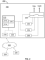
- Figure 2 illustrates a schematic representation 200 of the measurement device 100.
- the measurement device 100 includes a discharging circuit 202.
- the role of the discharging circuit 202 is to cause the pair of electrodes 104L, 104R to eliminate electric charges that could be stored thereon after previous DC measurements. It will be disclosed in further detail later.
- the measurement device 100 also includes a DC measurement circuit 204.
- the DC measurement circuit 204 is configured to carry out a DC measurement as disclosed previously and in particular an ESC measurement.
- the DC measurement circuit 204 will be disclosed in further detail later.
- the measurement device 100 also includes an AC measurement circuit 206.
- the AC measurement circuit 206 is configured to carry out an AC measurement as disclosed previously and in particular a BIA or an IPG.
- the AC measurement circuit 206 will be disclosed in further detail.
- the measurement device 100 also includes an ECG (electrocardiogram) measurement circuit (not represented on the drawings).
- the ECG measurement circuit is configured to carry out an ECG measurement.
- the ECG measurement circuit may include a reference electrode on the measurement plate and other acquisition electrodes on the handle.
- the measurement device 100 includes a commutator 208 to selectively connect or disconnect the pair of electrodes 104L, 104R to the discharging circuit 202. Indeed, the same pair of electrodes 104L, 104R is used for different measurements, such as one or more AC measurements and one or more DC measurements, and also the discharge. However, electronics may differ between AC and DC measurement circuits, the discharge circuit and also ECG measurement circuit.
- the commutator 208 is also configured to selectively connect or disconnect the pair of electrodes to the DC measurement circuit 204 and/or the AC measurement circuit 206 and/or to selectively connect or disconnect at least one electrode of the pair of electrodes to the ECG measurement circuit.
- the discharging circuit 202 may be included in the DC measurement circuit 204.
- the commutator 208 includes an open position, in which the electrodes are left floating.
- the commutator 208 may include switches to create physical connection between electrically conductive material.
- the measurement 100 includes a control circuitry 210.
- Control circuitry 210 may include a processor 212, a memory 214 storing instructions for the processor 212 and an I/O interface 216 to receive and send data.
- Control circuitry 210 may also include an analog to digital converter (ADC) and a digital to analog converter (DAC).
- ADC analog to digital converter
- DAC digital to analog converter
- Control circuit 210 is configured to instruct the commutator 208 to selectively connect the pair of electrodes 104L, 104R to the discharging circuit 202, the DC measurement circuit 204, the AC measurement circuit 206 and/or to switch to the open position.
- Control circuity 210 is further configured to control the DC measurement circuit 204 and/or the AC measurement circuit 206.
- control circuitry 210 is further configured to control the discharging circuit 202.
- the measurement device 100 may include a weight sensor 218.
- the weight sensor 218 may include load cells.
- the weight sensor 218 is configured to send weight data to control circuitry 210 which then is configured to determine a weight of the user based on the weight data.
- the weight sensor 2018 is typically arranged to receive a load from the measurement plate. It may be placed between the measurement plate and a mainframe or feet.
- Control circuitry 210 may also be configured to identify a user stepping on the body scale amongst a plurality of registered users.
- a registered user is a user for which the body scale stores a user profile containing data about the user. For example, such data includes weight data, age data and/or sex data.
- One way to identify a user is to use weight, for example to compare weight data obtained by the weight sensor 218 with weight data of the stored user profile and determines whether the weight data is to be attributed to the user profile.
- the measurement device 100 may further include a wireless module 220 to send and receive data from a communications network 222, which may be hybrid (wireless and/or wired, such as Bluetooth, Wi-Fi, Ethernet, etc.). Those data may be received from or sent to a remote server 224 and/or to a personal mobile phone 226 (e.g., smartphone, tablet, etc.). For example, the DC measurement values may be sent by control circuitry 210 to the server 224, which then forwards those data to the personal mobile phone 226.
- a wireless module 220 to send and receive data from a communications network 222, which may be hybrid (wireless and/or wired, such as Bluetooth, Wi-Fi, Ethernet, etc.). Those data may be received from or sent to a remote server 224 and/or to a personal mobile phone 226 (e.g., smartphone, tablet, etc.).
- the DC measurement values may be sent by control circuitry 210 to the server 224, which then forwards those data to the personal mobile phone 226.
- Figure 3 illustrates a more detailed version 300 of Figure 2 .
- Figure 4 illustrates some parts of the measurement device 100 in relation to a user body (e.g., the feet only, the hands only, the feet and the hands).
- the DC measurement circuit 202 may comprise a direct excitation source 302, such as a direct voltage source.
- the direct excitation source 302 may be connected to either one of the electrodes 104L, 104R of the pair of electrodes, which is thus called the anode Ea, through the commutator 208, controlled by control circuitry 210.
- the other electrode of the electrodes 104L, 104R which is not connected to the direct excitation source 302 is called the cathode Ec.
- the anode is the "left electrode 104L” and the "right electrode 104R" is the cathode Ec.
- the left electrode 104L may be the cathode Ec and the right electrode 104R may be the anode Ea.
- Control circuitry 210 is configured to control the direct excitation source 302, that is to say to send a voltage instruction to the direct excitation source 302.
- the voltage instruction may be for a constant direct voltage or for a series of decreasing steps.
- Voltage at the anode Ea is referred to as Va. This voltage usually corresponds to the instructed voltage to the direct excitation source 302.
- the DC measurement circuit 204 may also comprise a voltage sensor 304, configured to measure a voltage value. Voltage measured at the cathode Ec is referred to as Vc.
- the commutator 208 allows to change the electrical connection of the electrodes by switching some electrical connections between the electrodes 104L, 104R and other elements, and in particular the direct excitation source 202.
- the commutator 208 may be configured to invert the anode Ea and the cathode Ec on the pair of electrodes 104L, 104R.
- the commutator 208 may have further functions, as presented in document FR2114739 , for bioimpedance analysis for example.
- the commutator 208 has at least the following positions: an open position (electrodes 104L, 104R are left floating), a set of AC positions (in which the electrodes 104L, 104R are connected to the AC measurement circuit 206), a set of DC positions (in which the electrodes 104L, 104R are connected to the DC measurement circuit 204).
- Other positions such as ECG (electrocardiogram) positions are needed when the measurement device 100 is configured to perform an ECG.
- the set of AC positions may include several positions, depending on the AC measurement to be carried out (several BIAs, IPG, etc.). Document PCT/EP2022/086492 shows some examples.
- the set of DC positions may include a left DC position in which the left electrode 104L is connected to the DC excitation source 302 (usually called anode) and a right DC position in which the right electrode 104R is connected to the DC excitation source 302.
- the commutator 208 has also a set of discharging positions (in which the electrodes are connected to the discharging circuit 202). This set includes at least one position.
- the DC measurement circuit 204 also includes a measurement resistor 306 configured to compute a current value flowing through the body.
- the measurement resistor 306 is connected between a reference voltage and one electrode of the pair of electrodes 104L, 104R, e.g., that which is not connected to the direct excitation source 302, i.e. the cathode Ec.
- the commutator 208 may be used to switch the connection between on the one hand the measurement resistor 306 and on the other hand the left electrode 104L or the right electrode 104R so as to switch from an anode/cathode configuration to a cathode/anode configuration.
- the reference voltage may be a ground voltage of a ground of the measurement device 100.
- the measurement resistor 306 has an electrical resistance value Rm known from control circuitry 210.
- the electrical resistance value Rm is variable among a predetermined range and may be changed by control circuitry 210.
- the predetermined range goes from 3kOhms to 500kOhms or even between 9,6kOhms and 300kOhms.
- the measurement resistor 306 may include an array of resistors connected together with switches, so that to the predetermined range is constituted by a plurality of discrete values.
- the switches may be operated by control circuitry 210.
- the plurality is comprised between 4 and 32, even between 4 and 16, and may be 8.
- control circuitry 210 may determine a current iMes flowing through the user body. Conversely, as the reference electrode 108 is high impedance, the current therein is negligible, therefore generating no loss.
- the electrical resistance value Rm is variable among the predetermined range and zero.
- the measurement resistor 306 becomes equivalent to a wire when the value Rm is set to zero.
- the AC measurement circuit 206 includes an alternative excitation source 308 configured to generate an alternative current or voltage at the electrodes 104L, 104R.
- the alternative excitation source 308 may be used for bioimpedance such as BIA, for bioimpedance analysis - fat mass, water, bone, etc. or such as impedance plethysmography, IPG, etc.), as described in detail in document FR2114739 .
- the alternative excitation source 308 may be an alternative current source.
- the electrodes are connected to the alternative excitation source 308 through the commutator 208.
- the commutator 208 is activated by control circuitry 210.
- excitation source shall mean the direct excitation source or the alternative excitation source.
- the discharging circuit 202 includes at least one ground 310, which may be the same ground as that of the measurement resistance 306.
- the ground 310 causes the electrical charges to get or lose electrons to become electronically inactive.
- the pair of electrodes 104L, 104R is connected to the discharging circuit 202, the left electrode 104L and the right electrode 104R are both connected to the ground 310 or to two different grounds.
- the ground 310 is designed to be at a potential of 0V.
- Ground 310 may be a ground of control circuitry 210 (for example a ground of the processor 212).
- the ground 310 may be a signal ground and not an earth ground.
- the ground 310 may be that of control circuitry 210.
- the ground is a reference point for the whole electronic components linked to the ground 204. It carries a potential of 0V.
- At least one of the left electrode 104L and the right electrode 104R may be connected to the ground 310 though the commutator 208.
- the ground mentioned in relation to the resistance measurement and the ground 310 may be the same physical ground.
- ground 310 by connected to the ground 310, it is meant directly connected to the ground 310, with no impedance therebetween (only wires or near-zero impedance elements), as they would hinder the evacuation of the electrical charges.
- the discharging circuit 202 with the ground 310 is a dedicated circuit, which is not included in the DC measurement circuit 204. As disclosed before, the commutator 208 therefore has a set of dedicated discharging positions.
- a solution (called “bypass embodiment") is to set the resistance value Rm of the measurement resistor 306 to the zero value.
- control circuitry 210 may instruct the measurement resistor 306 to set the resistance value Rm to zero so that the measurement resistor 306 becomes a wire; the position of the commutator 208 is therefore one of the set of DC positions.
- the discharging circuit 202 includes the measurement resistor 306 set to the lowest value of the predetermined range and the ground 310 of the measurement resistance 306.
- control circuitry 210 may instruct the measurement resistor 306 to set the resistance value Rm to the lowest value of the predetermined range; the position of the commutator 208 is therefore one of the set of DC positions.
- the discharging circuit 202 includes an excitation source, such as the direct excitation source 302 or the alternative excitation source 308, set at a zero voltage.
- an excitation source such as the direct excitation source 302 or the alternative excitation source 308, set at a zero voltage.
- the pair of electrodes 104L, 104R is connected to the discharging circuit 202, the left electrode 104L and the right electrode 104R are both connected to one of the direct excitation source 302 and the alternative excitation source 308, or are both connected to one of them, with a voltage set by control circuity 210 close to zero or being equal to zero.
- the use of a low or zero voltage causes the electrical charges to get or lose electrons to become electronically inactive.
- the discharging circuit 202 combines the active discharging circuit and the ground passive discharging circuit or resistance passive discharging circuit.
- the hybrid discharging circuit includes the ground 310 and at least one of the direct excitation source 302 and the alternative excitation source 308.
- the discharging circuit 202 includes the ground 310 and one excitation source, such as the direct excitation source 302.
- one of the left electrode 104L and the right electrode 104R is connected to the ground and the other of the left electrode 104L and the right electrode 104R is connected to one of the direct excitation source 302 and the alternative excitation source 308 with a voltage set by control circuity 210 close to zero or being equal to zero.
- the hybrid discharging circuit 202 may include two configurations, typically enabled by the commutators 208 and therefore forms two positions of the sets of DC positions: one position in which the left electrode 104L is connected to the ground 310 and the right electrode 104R is connected to excitation source and one in which the left electrode 104L is connected to the excitation source and the right electrode 104R is connected to the ground 310.
- the connection to the ground 310 may be carried out using the bypass embodiment disclosed above.
- the position(s) of the commutator 208 is (are) therefore one(s) of the sets of DC positions.
- the hybrid discharging circuit includes the same as above except that the ground 310 is replaced by both the measurement resistor 308 at the lowest value of the predetermined range and the ground 310 of the measurement resistor 308.
- the electrodes 104L, 104R may be made of stainless steel, titanium, brass, nickel or an alloy thereof, or even conductive plastics.
- the electrodes 104L, 104R are made of indium tin oxide, known as ITO. ITO has different properties from stainless steel which favors electro-chemical reactions.
- the electrodes 104L, 104R may be a coating on the measurement plate 106.
- the coating is made of ITO and the measurement plate 106 is made of glass.
- the left electrode 104L is the anode Ea and the right electrode 104R is the cathode Ec.
- the left electrode 104L may be the cathode Ec and the right electrode 104R may be the anode Ea.
- Figure 4 illustrates a simplified representation 400 of a user on the measurement system.
- the user is represented in dots as the "user body".
- the left foot (or hand) may be in contact with the left electrode 104L which is the anode Ea, connected to the direct excitation source 302.
- the right foot (or hand) may be in contact with the right electrode 104R which is the cathode Ec, connected to the measurement resistor 306.
- Each foot (or hand) may also be connected to a reference electrode 108, which is the HiZ electrode, whose impedance is high thanks to one or more resistors 402.
- a measurement device without the reference electrodes 108 is also possible.
- Figure 5 illustrates a measurement method 500 to measure an ESC value, performed during a measurement period.
- a calibration method of the electrical resistance value Rm of the measurement resistor 306 may be performed before the measurement period.
- the calibration is aimed at setting the electrical resistance value Rm at an appropriate value, called calibration value Rcalib for acceptability ranges of the electronic components of control circuitry 210.
- Rm is chosen amongst the predetermined range.
- Control circuity 210 applies a first measurement voltage Va1 at the anode Ea using the direct excitation source 302 and obtain a first measured voltage Vc1 at the cathode Ec, using the voltage sensor 304.
- Control circuitry 210 may, at 504, in similar manner to 502, apply a second measurement voltage Va2 at the anode Ea and obtain a second measured voltage Vc2 at the cathode Ec.
- the second measurement voltage Va2 is different from the first measurement voltage Va1. Steps 502 and 504 are distinct and usually follow each other.
- the applied voltages Va at the anode Ea may be comprised between 0 and 5V, for example between 1V and 4V.
- control circuitry 204 may determine a measured current value iMes flowing through the user body. Therefore using data of step 402 and 404, control circuitry 204 may obtain two sets of data: (Va1 ; Vc1 ; iMes1) and (Va2 ; Vc2 ; iMes2).
- control circuitry 204 may obtain Vc or Vz (Vz being the voltage value of the HiZ electrode) and instead of Vc, control circuitry 210 may obtain Va or Vz.
- Vc is needed to determine the current flowing through the measurement resistor 306.
- Control circuitry 210 may generate, at 506, further sets of data using different voltages values (dashed lines on figure 4 ). For example, one additional set of data is generated.
- Control circuitry 210 determines, at 508, an ESC value, using the sets of data of 402 and 404 (and 406 if applicable).
- Measurement method 500 may be carried a second time with an anode-cathode inversion, to build the second curve on Figure 6 and the average of the slope may be carried out.
- the inversion is typically carried out using the commutator 208, with the left DC position and the right DC position.
- Va-Vz allows to have the ESC value of one foot (the left foot here is contacting the anode Ea), while Vc-Vz allows to have the ESC value of the other foot (the right foot here is contacting the cathode C).
- Control circuitry 210 may compute averages of those ESC values to output a single ESC value.
- a similar approach may be carried out without Vz, using Va1 and Va2, such that no high-Z electrode 108 is needed.
- control circuitry 210 may apply direct voltage steps of decreasing value. Each step may last between 300ms and 5s, preferably between 300ms and 700ms to reduce the length of the ESC measurement. In particular, this reduced duration is permitted by the pre-stabilization method that will be disclosed later.
- a direct voltage is applied to the electrodes 104 L, 104R at some point. This may lead to the stacking of electrical charges at the electrodes 104 L, 104R.
- the goal of the discharge is to reduce the influence of previous DC measurements on other measurements involving the electrodes.
- ESC measurements are generated using direct voltage and displacements of charges between the electrodes and the user's body (feet), notably through sweat generated upon stimulation of the sudoral glands by direct voltage. However, the sweat remaining on the electrodes may be electrically charged and such charges may alter the other measurements.
- Method 700 comprises, regardless of the order, discharging 702 at least one of the pair of electrodes 104 L, 104R (although preferably both) and carrying out a DC measurement 704.
- discharging 702 is performed before carrying out the DC measurement 704, so that the pair of electrodes is discharged before the DC measurement.
- discharging 702 is performed after carrying out the DC measurement 704, so that the pair of electrodes 104 L, 104R is put back into its former state, and is therefore ready for a new DC measurement 704 the next time the user steps on the scale.
- discharging 702 is performed before and after carrying out the DC measurement 704.
- the commutator 208 Before discharging 702, the commutator 208 may be in the open position, that is to say the pair of electrodes 104 L, 104R may be left floating.
- Carrying out an AC measurement 706 comprises control circuitry 210 to instruct the commutator 208 to connect the pair of electrodes 104L, 104R to the AC measurement circuit 206 and to instruct the alternative excitation source 308 to generate AC excitation.
- AC measurement 706 may include BIA or IPG (to compute PWV for example).
- Carrying out a DC measurement 704 comprises control circuitry 210 to instruct the commutator 208 to connect the electrodes 104L, 104R (or at least one) to the DC measurement circuit 204 and to instruct the direction excitation source 302 to generate a DC excitation.
- the commutator 208 may be therefore in the left DC position or the right DC position.
- Discharging 702 comprises control circuitry 210 to instruct the commutator 208 to a position of the set of discharging positions, that is to say to connect the electrodes 104L, 104R (or at least one) to the discharging circuit 202.
- the discharging circuit 202 is a ground passive discharging circuit, the electrical charges will naturally be neutralized thanks to the ground 310 that sets a zero potential to the electrodes 104 L, 104R.
- control circuitry 210 sets the resistance value of the measurement resistor 306 to zero.
- the discharging circuit is the resistance passive discharging circuit, the electrical charges will naturally be neutralized, but at a slower rate thanks to the ground 310 and the measurement resistor 306.
- control circuitry 210 sets the resistance value of the measurement resistor 306 to the lowest value of the predetermined range.
- discharge 702 further comprises control circuitry 210 to instruct the excitation source 302 to set a low or zero voltage.
- control circuitry 210 instructs the direct excitation source 302 to set a zero voltage.
- discharging 702 may further include inverting between the left/right configuration to the right/left configuration, so that each of the left electrode 104L and right electrode 104R is successively connected to the ground 310 and the excitation source 302 set at a low or zero voltage. This ensures a better symmetry in the discharging process. For example, such inversion can be done by switching between the right DC position and the left DC position, in the embodiment in which the discharging circuit is included in the DC measurement circuit.
- method 700 further includes, before or after discharging 702, carrying out an AC measurement 706.
- discharging 702 is performed before, to discharge the electrodes for the AC measurement.
- AC measurement 706 is carried out before the DC measurement 704, to avoid having to discharge the electrodes before the AC measurement 706.
- Discharging 702 may last between 2s and 8s, even between 5s and 7s.
- Discharging 702 takes some time. However, the user must spend as little time as possible on the measurement device. To improve to measurement flow, the discharging may be carried out during the weighing and/or identification steps of the measurement device.
- method 700 may further comprise acquiring weight data 802 by control circuit 210 using the weigh sensor.
- Acquiring weight data 802 may last between 1s and 4s.
- Discharging 702 may be carried out during acquiring weight data 802, or at least partially during, so that the overall duration of the measurement sequence is not increased or only slightly increased.
- method 700 may further comprise identifying 804 a user profile stored in the measurement device 100. Discharging 702 may be carried out during identifying 804, or at least partially during.
- discharging 702 is performed at least before performing a DC measurement.
- the embodiment of identifying 804 may be carried out using other data than weight data (impedance data, proximity sensor, Bluetooth detection, etc.).
- the measurement may be any type of measurement using a direct source of excitation, such a direct voltage source used for the ESC measurement or a direct source of current.
Landscapes
- Health & Medical Sciences (AREA)
- Life Sciences & Earth Sciences (AREA)
- Physics & Mathematics (AREA)
- Surgery (AREA)
- General Health & Medical Sciences (AREA)
- Engineering & Computer Science (AREA)
- Biomedical Technology (AREA)
- Heart & Thoracic Surgery (AREA)
- Medical Informatics (AREA)
- Molecular Biology (AREA)
- Biophysics (AREA)
- Animal Behavior & Ethology (AREA)
- Pathology (AREA)
- Public Health (AREA)
- Veterinary Medicine (AREA)
- Dermatology (AREA)
- Nuclear Medicine, Radiotherapy & Molecular Imaging (AREA)
- Radiology & Medical Imaging (AREA)
- Cardiology (AREA)
- General Physics & Mathematics (AREA)
- Measurement And Recording Of Electrical Phenomena And Electrical Characteristics Of The Living Body (AREA)
Priority Applications (2)
| Application Number | Priority Date | Filing Date | Title |
|---|---|---|---|
| EP23176230.3A EP4470458A1 (de) | 2023-05-30 | 2023-05-30 | Elektrodenentladung an einer messvorrichtung |
| US18/673,047 US20240398251A1 (en) | 2023-05-30 | 2024-05-23 | Electrode discharge on a measurement device |
Applications Claiming Priority (1)
| Application Number | Priority Date | Filing Date | Title |
|---|---|---|---|
| EP23176230.3A EP4470458A1 (de) | 2023-05-30 | 2023-05-30 | Elektrodenentladung an einer messvorrichtung |
Publications (1)
| Publication Number | Publication Date |
|---|---|
| EP4470458A1 true EP4470458A1 (de) | 2024-12-04 |
Family
ID=86609460
Family Applications (1)
| Application Number | Title | Priority Date | Filing Date |
|---|---|---|---|
| EP23176230.3A Pending EP4470458A1 (de) | 2023-05-30 | 2023-05-30 | Elektrodenentladung an einer messvorrichtung |
Country Status (2)
| Country | Link |
|---|---|
| US (1) | US20240398251A1 (de) |
| EP (1) | EP4470458A1 (de) |
Citations (13)
| Publication number | Priority date | Publication date | Assignee | Title |
|---|---|---|---|---|
| FR2114739A5 (de) | 1970-11-16 | 1972-06-05 | Dusenbery Co John | |
| EP1091215B1 (de) * | 1999-09-30 | 2005-03-16 | Tanita Corporation | Vorrichtung zur bioelektrischen Impedanzmessung |
| WO2006136598A2 (fr) | 2005-06-22 | 2006-12-28 | Annick Nicole Lydie Tournefier | Systeme et procede d'analyse electrophysiologique |
| US20080015641A1 (en) * | 2006-07-12 | 2008-01-17 | Cyberonics, Inc. | Implantable Medical Device Charge Balance Assessment |
| WO2008107324A1 (fr) | 2007-02-23 | 2008-09-12 | Impeto Medical | Systeme d'analyse electrophysiologique |
| WO2013075963A1 (fr) | 2011-11-21 | 2013-05-30 | Impeto Medical | Procede d'analyse physiologique de fiabilite accrue |
| WO2014033105A1 (fr) | 2012-08-28 | 2014-03-06 | Impeto Medical | Systeme d'analyse electrophysiologique ameliore |
| US20140257119A1 (en) * | 2011-11-18 | 2014-09-11 | Charles LeMay | Patient Electrode Impedance Measurement |
| WO2015036530A1 (fr) | 2013-09-12 | 2015-03-19 | Impeto Medical | Procede d'analyse physiologique par stabilisation d'une surtension |
| WO2016083432A1 (fr) | 2014-11-25 | 2016-06-02 | Impeto Medical | Dispositif de releve de donnees electrophysiologiques de fiabilite accrue |
| US20170105646A1 (en) * | 2014-06-26 | 2017-04-20 | Biopeak Corporation | Multi-parameter sensor system for measuring physiological signals |
| CN110840454B (zh) * | 2019-12-21 | 2021-03-23 | 深圳市杰纳瑞医疗仪器股份有限公司 | 一种脑电信号采集装置和方法 |
| US20210321893A1 (en) * | 2018-03-29 | 2021-10-21 | Hangzhou Megasens Technologies Co., Ltd. | Electrode Multiplexed Physiological Parameter Monitoring Finger Ring |
Family Cites Families (3)
| Publication number | Priority date | Publication date | Assignee | Title |
|---|---|---|---|---|
| US10610159B2 (en) * | 2012-10-07 | 2020-04-07 | Rhythm Diagnostic Systems, Inc. | Health monitoring systems and methods |
| US10092203B2 (en) * | 2015-08-21 | 2018-10-09 | Verily Life Sciences Llc | Using skin resistance measurements to determine timing of bio-telemetry measurements |
| US10342492B2 (en) * | 2016-01-05 | 2019-07-09 | Tosense, Inc. | Floormat physiological sensor |
-
2023
- 2023-05-30 EP EP23176230.3A patent/EP4470458A1/de active Pending
-
2024
- 2024-05-23 US US18/673,047 patent/US20240398251A1/en active Pending
Patent Citations (13)
| Publication number | Priority date | Publication date | Assignee | Title |
|---|---|---|---|---|
| FR2114739A5 (de) | 1970-11-16 | 1972-06-05 | Dusenbery Co John | |
| EP1091215B1 (de) * | 1999-09-30 | 2005-03-16 | Tanita Corporation | Vorrichtung zur bioelektrischen Impedanzmessung |
| WO2006136598A2 (fr) | 2005-06-22 | 2006-12-28 | Annick Nicole Lydie Tournefier | Systeme et procede d'analyse electrophysiologique |
| US20080015641A1 (en) * | 2006-07-12 | 2008-01-17 | Cyberonics, Inc. | Implantable Medical Device Charge Balance Assessment |
| WO2008107324A1 (fr) | 2007-02-23 | 2008-09-12 | Impeto Medical | Systeme d'analyse electrophysiologique |
| US20140257119A1 (en) * | 2011-11-18 | 2014-09-11 | Charles LeMay | Patient Electrode Impedance Measurement |
| WO2013075963A1 (fr) | 2011-11-21 | 2013-05-30 | Impeto Medical | Procede d'analyse physiologique de fiabilite accrue |
| WO2014033105A1 (fr) | 2012-08-28 | 2014-03-06 | Impeto Medical | Systeme d'analyse electrophysiologique ameliore |
| WO2015036530A1 (fr) | 2013-09-12 | 2015-03-19 | Impeto Medical | Procede d'analyse physiologique par stabilisation d'une surtension |
| US20170105646A1 (en) * | 2014-06-26 | 2017-04-20 | Biopeak Corporation | Multi-parameter sensor system for measuring physiological signals |
| WO2016083432A1 (fr) | 2014-11-25 | 2016-06-02 | Impeto Medical | Dispositif de releve de donnees electrophysiologiques de fiabilite accrue |
| US20210321893A1 (en) * | 2018-03-29 | 2021-10-21 | Hangzhou Megasens Technologies Co., Ltd. | Electrode Multiplexed Physiological Parameter Monitoring Finger Ring |
| CN110840454B (zh) * | 2019-12-21 | 2021-03-23 | 深圳市杰纳瑞医疗仪器股份有限公司 | 一种脑电信号采集装置和方法 |
Non-Patent Citations (2)
| Title |
|---|
| ROSA BRUNO M G ET AL: "Smart wireless headphone for cardiovascular and stress monitoring", 2017 IEEE 14TH INTERNATIONAL CONFERENCE ON WEARABLE AND IMPLANTABLE BODY SENSOR NETWORKS (BSN), IEEE, 9 May 2017 (2017-05-09), pages 75 - 78, XP033101774, DOI: 10.1109/BSN.2017.7936011 * |
| XU JIAWEI ET AL: "A 36 [mu]W 1.1 mm2 Reconfigurable Analog Front-End for Cardiovascular and Respiratory Signals Recording", IEEE TRANSACTIONS ON BIOMEDICAL CIRCUITS AND SYSTEMS, IEEE, US, vol. 12, no. 4, 1 August 2018 (2018-08-01), pages 774 - 783, XP011688651, ISSN: 1932-4545, [retrieved on 20180814], DOI: 10.1109/TBCAS.2018.2814699 * |
Also Published As
| Publication number | Publication date |
|---|---|
| US20240398251A1 (en) | 2024-12-05 |
Similar Documents
| Publication | Publication Date | Title |
|---|---|---|
| US8606353B2 (en) | Method, medium, and apparatus measuring biological signals using multi-electrode module, with a lead search | |
| US6473643B2 (en) | Method and apparatus for measuring body fat | |
| Penney | Theory and cardiac applications of electrical impedance measurements. | |
| KR102335768B1 (ko) | 체지방을 측정하는 방법 및 장치 | |
| JP4074236B2 (ja) | 体組成情報取得装置 | |
| US6360124B1 (en) | Handheld bioelectric impedance measuring apparatus | |
| US20030088197A1 (en) | Daily-life disability related physical information determining apparatus | |
| US20080072691A1 (en) | Method and System for Generating Control Signals for Controlling a Controllable Device | |
| KR970000189A (ko) | 생체전기 임피던스법을 이용한 인체 성분분석 및 그 분석방법 | |
| US20060282006A1 (en) | Body fat scale having transparent electrodes | |
| CN111317472B (zh) | 具有测量心率体脂功能一体的检测系统 | |
| US20130317386A1 (en) | Body weight management device having function of predicting body weight variation | |
| EP4470458A1 (de) | Elektrodenentladung an einer messvorrichtung | |
| CN112336331A (zh) | 一种局部人体成分数据处理方法及分析仪 | |
| JP4155170B2 (ja) | 体脂肪測定装置 | |
| US8233975B2 (en) | Method utilizing two wire electrode oscillator system for determining body impedance | |
| Nikishov et al. | Bio-electrical impedance analysis for wrist-wearable devices | |
| EP4382040A1 (de) | Verbessertes esc-bewertungsverfahren | |
| KR100542795B1 (ko) | 체지방 측정기능을 가진 휴대용 통신단말기 | |
| KR102155911B1 (ko) | 신체 불균형에 대한 보정기능을 갖는 체성분 분석장치 | |
| KR101864952B1 (ko) | 측정값 보정기능을 가진 체성분분석기 | |
| US11510609B2 (en) | Muscle mass estimation method, muscle mass estimation device, and storage medium storing a muscle mass estimation program | |
| EP4549888A1 (de) | Wägesystem mit mehreren messsequenzen | |
| CN113768487A (zh) | 用户体脂检测方法和装置、计算机设备以及介质 | |
| CN201244024Y (zh) | 人体成分检测仪 |
Legal Events
| Date | Code | Title | Description |
|---|---|---|---|
| PUAI | Public reference made under article 153(3) epc to a published international application that has entered the european phase |
Free format text: ORIGINAL CODE: 0009012 |
|
| STAA | Information on the status of an ep patent application or granted ep patent |
Free format text: STATUS: THE APPLICATION HAS BEEN PUBLISHED |
|
| AK | Designated contracting states |
Kind code of ref document: A1 Designated state(s): AL AT BE BG CH CY CZ DE DK EE ES FI FR GB GR HR HU IE IS IT LI LT LU LV MC ME MK MT NL NO PL PT RO RS SE SI SK SM TR |
|
| STAA | Information on the status of an ep patent application or granted ep patent |
Free format text: STATUS: REQUEST FOR EXAMINATION WAS MADE |
|
| 17P | Request for examination filed |
Effective date: 20250520 |