EP4470650A1 - Luftfilter mit deckelbefestigungssystem und verfahren zur montage eines solchen filters - Google Patents
Luftfilter mit deckelbefestigungssystem und verfahren zur montage eines solchen filters Download PDFInfo
- Publication number
- EP4470650A1 EP4470650A1 EP24177113.8A EP24177113A EP4470650A1 EP 4470650 A1 EP4470650 A1 EP 4470650A1 EP 24177113 A EP24177113 A EP 24177113A EP 4470650 A1 EP4470650 A1 EP 4470650A1
- Authority
- EP
- European Patent Office
- Prior art keywords
- cover
- housing
- component
- opening
- housing component
- Prior art date
- Legal status (The legal status is an assumption and is not a legal conclusion. Google has not performed a legal analysis and makes no representation as to the accuracy of the status listed.)
- Granted
Links
Images


Classifications
-
- B—PERFORMING OPERATIONS; TRANSPORTING
- B01—PHYSICAL OR CHEMICAL PROCESSES OR APPARATUS IN GENERAL
- B01D—SEPARATION
- B01D46/00—Filters or filtering processes specially modified for separating dispersed particles from gases or vapours
- B01D46/0002—Casings; Housings; Frame constructions
- B01D46/0005—Mounting of filtering elements within casings, housings or frames
-
- B—PERFORMING OPERATIONS; TRANSPORTING
- B01—PHYSICAL OR CHEMICAL PROCESSES OR APPARATUS IN GENERAL
- B01D—SEPARATION
- B01D2265/00—Casings, housings or mounting for filters specially adapted for separating dispersed particles from gases or vapours
- B01D2265/02—Non-permanent measures for connecting different parts of the filter
- B01D2265/028—Snap, latch or clip connecting means
-
- B—PERFORMING OPERATIONS; TRANSPORTING
- B01—PHYSICAL OR CHEMICAL PROCESSES OR APPARATUS IN GENERAL
- B01D—SEPARATION
- B01D2279/00—Filters adapted for separating dispersed particles from gases or vapours specially modified for specific uses
- B01D2279/60—Filters adapted for separating dispersed particles from gases or vapours specially modified for specific uses for the intake of internal combustion engines or turbines
Definitions
- the invention relates to the field of air filters, in particular filters intended for the intake air of internal combustion engines or a fuel cell of a motor vehicle.
- the present disclosure relates more particularly to an air filter having two housing parts assembled by a fastening assembly. It also relates to a method of assembling an air filter.
- a maintenance operator has operable part(s) for manually unlocking the cover which can be easily/directly accessible on the top of the cover by allowing a tightening action in the locked state on a given side of the cover, for example to crush a seal, even when the bulk in the vicinity of the housing prevents any lateral access on this given side.
- the top face can constitute a top of the cover, which for example is hollow with at least one domed part, possibly on the outlet side.
- the housing component typically underlying the cover, has an annular upper portion which defines the opening (upper axial opening) closed by the cover and through which the separation means are inserted prior to closure by the cover.
- the upper actuating portion may protrude above the cover, for example so that actuating the unlocking at this element requires a small lowering of the operator's hand compared to the action to then raise the unlocked cover.
- the top face can connect to a side wall of the cover (for example, a rectangular section wall) by one or more transition zones with a curved profile and each forming a portion of convex external surface, facilitating the radial tilting inwards of the upper actuating portion.
- the upper actuating portion can be placed in a predetermined position locking the engagement of the lower anchoring portion under the gripping edge.
- the cover may provide two fixing regions or receiving parts, in order to distribute two locking members on two distinct sides of the cover, having on each of these members, an actuating end which reaches or exceeds from above a peak of the cover or an outlet of the cover.
- the second attachment system may comprise the clasp element as a first locking element (with its actuating end constituting a high point of this first element) and comprises a second locking element (also with its actuating end constituting a high point of this second element) also having a lower anchoring portion and an upper actuating portion, in particular of the ratchet type, adapted to move, preferably by pivoting it, the lower anchoring portion of the second locking element.
- the edge of the housing component has two sides, distinct from another side provided with the hinge connection, on which are distributed two receiving parts, for engagement respectively with one and the other of the lower anchoring portions of the first locking element and the second locking element.
- the lower anchoring portion may be at least twice as long as it is wide.
- the lower anchoring portion may be in the form of a (U-shaped) rider with a hooked end.
- two brackets each inverted U-shaped
- two lower portions each forming a rider may be provided, for example only on two sides (sides perpendicular to the hinge connection in options allowing the tightening to be well distributed).
- a seal of the filter element may be sandwich-shaped when the riders are engaged with the brackets and the seal is then ensured between the upstream zone and the downstream zone in the filter chamber.
- the gripping edge may form the junction between two legs of a bridge constituting the fixing bracket.
- the configuration with two force legs allows transmission of the closing movement to the housing component.
- the closing carried out by the lever arm of the wire clips or similar clasp elements allows the cover to be compressed onto the housing component/body, possibly multiplying the force transfer points/regions when each gripping edge is delimited between legs integral with the housing component.
- the cover is domed at least on one side opposite the hinge connection.
- the cover may include a fastening means on which the upper actuating portion is pivotally mounted.
- the fastening means may form a female socket for connecting at least one male end of the upper actuating portion.
- the fastening means may be disposed on a convex portion of the cover that extends radially inwardly relative to a fastening flange formed on the cover.
- the actuating part When the cover is arranged in a closing configuration (by lowering this cover using the hinged connection), the actuating part is movable between a retracted position (radially offset outwards for example), in which the anchoring part can disengage from the gripping edge relative to the cover and a close position.
- the cover and housing component form a housing for defining a filter chamber.
- the outlet may be disposed on the cover, opposite the hinged connection, such as being angled.
- the outlet allows a stream of purified air exiting the filter element to leave the filter chamber, optionally by directing the exit stream to the same side of the housing as that including the inlet.
- the filter element is, for example, distal to the top face of the housing.
- a region of the filter chamber that is a region downstream of the filter element may be defined, typically under the top face, in communication with the outlet.
- a downstream zone (downstream of the separation means) may be delimited between an inner face of the cover and an outlet face of the filter element, knowing that the upper actuating portion is connected to the cover on a wall portion including the inner face of the cover and distal to the outlet face.
- An annular portion of the cover may constitute a transition/separation region between a flange of the cover and an upper portion of the cover allowing the connection of the locking element or upper actuating part, this upper portion having for example an inner face vertically facing the opening.
- This upper portion may be convex and adjacent to a depression whose bottom constitutes a lower portion of the cover formed between the hinge connection and this upper portion.
- the housing may have a junction between the base and the lid that slopes downward from the hinge, for example such that two lower edges of the lid each move further away from a virtual plane passing through the outlet and the hinge, the further away (downward) one moves from the hinge.
- the housing is provided with a cover carrying the outlet and removably fixed on an annular upper portion provided on a part constituting the housing component.
- the cover may be selectively attached to the housing component alone.
- the cover may be without a gasket.
- the closing means may be distributed around an outlet of the device for the evacuation of purified air, said outlet being formed laterally on the cover, these closing means being actuable to authorize or trigger the unlocking of the closed state, the upper actuating portion being optionally movable by a thrust exerted from the top of the cover.
- the filter/device is used to filter air supplied to a battery or fuel cell system.
- the device is used to filter air supplied to an air supply circuit of an internal combustion engine, in particular for a vehicle engine (e.g. an automobile).
- the (peripheral) seal provided on the filter element is capable of applying, when there is no longer any clamping exerted by the second fastening system, a separation force to the filter element to slightly raise the latter and/or to push the cover upwards.
- a return effect towards the nominal shape of the seal can allow an expansion effect in the direction at least along a vertical/perpendicular direction to the hinge connection and perpendicular to the plane of the opening of the housing component.
- a filtering device 1 intended for the purification of a raw air flow F (possibly pre-filtered) coming from the outside, this device/filter being in the suction line of an internal combustion engine or an engine component, for example an accumulator or an energy source requiring cooling (typically an on-board source in a vehicle - a fuel cell for example).
- This device 1 can be placed in an air intake line or circuit for an internal combustion engine.
- the device 1 can be arranged in the line, as a last filter before an intake manifold of an engine, a similar inlet for receiving purified air of an engine or a housing of an electrochemical generator.
- the device 1 comprises a housing 2 provided with an inlet 3 and an outlet 4.
- the interior volume of the housing 2 includes a filtration chamber.
- the filtering part of the device 1, housed in the interior volume V may comprise or consist of separation means 5, 6 making it possible to separate an upstream zone Z1, provided in the filtration chamber and communicating with the inlet 3, from a downstream zone Z2 communicating with the outlet 4.
- a flow of purified air F' exits through an outlet face F2 of the separation means 5, 6, passing through the downstream zone Z2 and reaching the outlet 4.
- the filtration chamber is surrounded by a side wall of the housing 2, which is a generally tubular wall.
- the housing component 14 forming the bottom 2a of the housing 2 forms at least part of this side wall.
- the housing component 14 may have two sides, a front face and a rear face opposite the front face.
- a wide opening O2 is formed at the upper end of the housing component 14, this opening O2 being delimited by an annular border B2 which may include a flange 24 or similar external projecting edge.
- the air filtration device 1 typically includes a housing 2, closed during operation, which opens by a cover 10 articulated via a hinged connection 8 on the housing component 14.
- the hinged connection 8 may correspond to a first attachment system of the housing 2.
- a second attachment system is further provided to allow the locking of the cover 10 with a tightening of this cover 10 to keep it closed against an edge B2 formed at the upper end of the housing component 14.
- the unlocking of the cover 10 may be allowed by at least one clasp element V1, V2 and possibly one or more additional clips 7.
- the edge B2 may include two parallel (possibly rectilinear) sides 21, 22, distinct from a side 20 integrated into the hinge connection 8. On these two sides 21, 22, two uprights, stirrups or similar projecting parts form a gripping edge B11 to cooperate with a complementary hooking part secured to the cover 10, in a region located higher than the flange 23 of the cover which comes into contact with the edge B2.
- one or two locking elements forming clasps V1, V2 may be provided, each with a lower anchoring portion 80 and an upper actuating portion 15, 16 connected together to form a part of the clasp element V1, V2 carried by the cover 10.
- the support structure MF1, MF2 of the clasp element V1, V2 may be formed laterally on the cover 10 which is domed, at least in the area where such a support structure is located.
- the upper actuating portion is for example of the rocker type (rocker latch) for pulling the anchoring portion in an upward direction during a locking action.
- the cover 10 can carry each upper actuating portion 15, 16 in a domed area and/or in an area close to a top of the cover.
- the lower anchoring portion 80 can be driven by the upper actuating portion designed as a separate part, for example by means of a hinge connection located on the top of the lower anchoring portion 80 and possibly above a pivot connection LP making it possible to connect the upper actuating portion to the cover 10.
- the upper actuating portion 15, 16 or comparable clip 115 may be movable, for example with a lever effect and/or a thrust effect, to drive the lower anchoring portion 80 so as to engage the latter under a gripping edge B11 provided in the component 14 in response to an action such as a press (by a finger of the operator, typically).
- the actuation may be of the tool-free type to allow the hinged cover 10 to be unlocked and lifted relative to the remainder of the housing component 14 which forms the fixed part of the housing, at least during a replacement operation involving all or part of the separation means 5, 6.
- Two respective fixings can be permitted by providing two gripping edges B11 distributed on stirrups 11 or similar projecting members of the component 14.
- Two receiving parts MF1, MF2, opposite one another in the cover 10, can serve to house and retain one and the other of the lower anchoring portions 80 of a first locking element V1 and of a second locking element V2.
- the receiving part MF1, MF2 of such a distal clip 15, 16, 115 is located away from the opening 02, with a spacing distance of more than two thirds of the total height (which is a maximum height) of the cover 10. Therefore, the fixing of the part carried by the cover 10 is raised and particularly away from the junction J.
- the upper actuating portion 15, 16, pivotally mounted on the cover 10, can project upwards by extending upwards, in the closed and locked configuration of the housing 2.
- this upper actuating portion 15, 16 extends for example radially inwards, where appropriate having a grippable portion, in the form of a rigid handle or tab, and can be pushed radially outwards in order to allow the cover 10 to be unlocked.
- two upper actuation portions 15, 16 are accessible from above the cover 10, without the need for the operator's fingers to go to one side of the housing 2 near the junction J between the component 14 and the cover 10.
- Such an upper actuation portion 15, 16 extends closer to the top face (or summit) of the cover 10 than to the junction J with the component 14.
- each upper actuation portion 15, 16 projects vertically higher/above the cover 10.
- the device 1 may have separation means 5, 6, permeable and compact, possibly in the form of a filter block with several superimposed layers.
- An optional prefilter or first medium 5 is for example provided and a filter component or second medium 6 is also arranged in the filtration chamber delimited by the housing 2 of the device 1.
- This filter component 6 can separate particles finer than the separation allowed by the prefilter 5, in particular by separating particles of submillimeter and/or submicrometer size.
- the device 1 forming an air filter may have one or more filtration layers.
- the filtration layers may be superimposed or extend parallel to each other.
- One of the layers is of the cellulosic type.
- a layer may include an adsorption material, possibly carbon, for example in the form of activated carbon.
- An area with an annular seal J10 may delimit a periphery of the filter part including these layers.
- the filter part corresponds for example to a filter element EF inserted functionally as a cartridge, thanks to a removable attachment.
- the seal J10 is at base of an elastomer, for example EPDM. It may have a U-shaped section, enclosing a radially projecting edge extending around the circumference of a frame of the EF filter element.
- the removable attachment of the filter element EF can be carried out on a frame or an annular rim formed in the housing component 14.
- the seal J10 can be in sealing contact on an inner circumference of the housing component 14, for example by coming to bear from above on a seat zone of the same general shape (for example rectangular) and same dimensions as the seal J10 (see for example the non-limiting case of the figure 4 ).
- the filter element EF is removably mounted by optionally extending under the outlet 4 belonging to the cover 10.
- the distance of the inlet face F1 of the filter element EF from the bottom 2a may be greater than or equal to the height of the inlet 3.
- a water collection/decantation zone may be provided separated by this filter element EF.
- the large vertical distance from the bottom 2a makes it possible to have an air reserve inside the housing component 14, directly under the filter element EF.
- the filter element EF may have a filter panel format, with a delimiting frame on the outside. This frame may be arranged horizontally, with a joint J10 which may optionally be horizontal or which may be inclined with an upward inclination directly from the hinge connection 8.
- the axis A defined by the hinge components 8a of the connection 8 may be substantially horizontal in the assembled state.
- the housing 2 may be mounted vertically or generally vertically in a vehicle, having a lower end (forming the bottom 2a) parallel to the extension of the filter element EF.
- the housing 2 has an inlet 3 and an outlet 4 which are each distant from the bottom 2a delimiting a bottom of the filtration chamber.
- the filter element EF makes it possible to retain aqueous liquids, each layer being permeable to air.
- the filter element EF makes it possible to delimit a clean zone, corresponding to the downstream zone Z2 which extends in particular in a hollow of the cover 10.
- the face F2 can form an upper face of the filter element EF, arranged/disposed lower than the grip edge B11 (under the operating conditions of the device 1).
- the first face is typically arranged opposite the bottom 2a and can be part of a prefilter or a first layer of the filter element which extends selectively below the level/plane of the junction J (and thus below a plane of the opening 02).
- the frame may support the seal J10 on the outside of its side wall which is for example rectangular or polygonal in section.
- the side wall of the frame includes at least four sides and an annular internal rim forming a support from below for the second filter medium 6 which extends (optionally only partly) into a recess in the cover 10.
- the housing component 14 made in one piece or resulting from an assembly of different parts, can be substantially as wide as it is deep (with a width dimension measured along the direction of the axis A of the articulation members/members 8a of the hinge connection 8. It can even be deeper than wide on the side of the hinge connection 8.
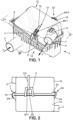
- the flow F can flow first in a direction tangential or parallel to a plane of the inlet face F1 of the filter element and/or to a plane of the opening O2 (upper opening) of the housing component 14, as visible in the figure 1 .
- a housing 2 is shown having an inlet 3 and an outlet 4 oriented on the same side, with the inlet close to a side where the hinged connection 8 is located, and the outlet 4 provided on the cover 10 by connecting to the cover 10 in an angled manner on a cover face opposite the hinged connection 8.
- This arrangement can make it possible to optimize the integration of the housing 2 in a cluttered environment.
- other orientations can be used for the inlet 3 and/or the outlet 4.
- the opening O2 of the housing component 14 may constitute the only access through which the filter element EF is mounted in the housing component 14.
- the cover 10 may have a domed shape at least in a region of the closing part P10 which covers the opening O2.
- the articulation of the cover 10 is carried out selectively on one side of the component 14, for example a substantially rectilinear side, which makes it possible to border the opening O2.
- the cover 10 is domed at least opposite the hinge connection 8.
- a depression 10d clearly visible in the case of the figure 3 , makes it possible to locally limit the size of the cover 10. This depression 10d is adjacent to the hinge connection 8 and adjacent to an edge portion located directly above an end piece forming the inlet 3 of the housing component.
- the cover 10 can be designed with a thinning or a depression 10d arranged at least on the side of the inlet 3 and in an angular sector which can be distinct from the angular sectors where the elements of the second attachment system are distributed.
- This type of arrangement allows for the integration of external components, tubes and/or tubing in an area both close to the hinge connection 8 and the inlet 3, which can then leave room for the opposite side of the cover 10, which requires some clearance so that the cover 10 is raised sufficiently (without interference with other components), to uncover the O2 opening when the filter element EF has to be changed.
- the outlet 4 has a certain mobility due to its integration on the cover 10, at a distance from the hinge connection 8.
- At least one clip 7 may be provided on the side opposite the connection 8 forming the first attachment system, which belongs to the second attachment system.
- the second attachment system allows manual attachment, without tools in preferred options.
- the cover 10 includes a rim for attaching the clip 7, preferably with a delimitation between two guide edges.
- the outlet 4 for the purified air can be offset vertically (higher) relative to the junction J, which makes it possible to locate the clip 7 under the opening constituting the outlet 4 with accessibility to this clip 7 being permitted due to the available external spacing provided for the movement of the hinged cover 10.
- a clip 7 has for example a curved structure with an elastic return effect towards a semi-circular or similar conformation, which can correspond to the conformation illustrated in dotted lines on the figure 4 .
- a clip is optionally made of a single metal piece.
- the housing component 14 includes a retaining seat SR for retaining a lower end of the clip 7, which here includes a semi-circular spring-action blade 70.
- the clip 7 may be carried by the housing component 14 in a state disconnected from the cover 10.
- an attachment region is provided on the cover 10, for example in the form of a rim for engagement with a removable retainer of a radially inner part of the clip 7. Since the clip 7 has a handling/gripping tab, which can form the upper end of the clip 7, a user can move the top of the clip 7 until engagement on the rim is obtained.
- a rim can also be located in a notch of an annual return provided in a flange 23 of the cover 10 (an upper groove then being delimited by the cover between its side wall and this ascending return).
- the handling tab may have a radial extension to overlap the rim while projecting radially outwardly from the cover 10.
- the two delimiting edges of the notch may guide the lowering of a curved portion of the clip 7 while avoiding undesirable twisting movements when placing the clip in its gripping position to retain the cover 10.
- Such a curved portion, forming an open loop, for analogous part may have a free end projecting radially outwardly, capable of constituting a gripping tab 72.
- this clip 7 is located in the same angular sector as the outlet 4 (also provided on the cover 10) which already requires a free space (for the movement when lifting the cover 10).
- the outlet 4 is bent to form a rear portion 44 of the elbow.
- the Y axis in the outlet of the outlet 4 can be angularly offset by more than 60°; for example approximately 90°, relative to the vertical median plane P4 separating the face of the cover where this outlet 4 is formed into two halves.
- the clip 7 has, for example, a control/gripping tab 72 visible from above and accessible by running along/passing behind the rear portion 44 of the elbow of the outlet 4. More broadly, it is possible to provide for a co-location of the gripping part of the clip 7 and the outlet 4, on the same side of the cover opposite/distal to the first attachment system, while having a slight offset for access to the clip 7, at least to make it visible in a top view of the device in the closed state of the cover 10.
- the cover 10 is kept closed with the junction J which can extend along a plane P, when each clasp element V1, V2 is in the locked state.
- the clasp element V1, V2 has an upper actuating portion 15, 16 which is attached to the cover 10.
- this upper portion 15, 16 is located on a support region located not only above the plane P (plane which can be inclined/not parallel to the bottom 2a) but also above a plane P1 passing through the hinge connection 8 and intersecting a central axis of the outlet 4.
- the upper portion 15, 16 is designed and arranged so as to be able to extend upwards from a connection end in rotation with the support region.
- this upper portion 15, 16 is a ratchet portion which can rise from above a sealing part P10 of the cover 10.
- the part of the clasp element V1, V2 carried by the cover 10 comprises the lower anchoring portion 80 and the upper actuation portion 15, 16 which each have a wire structure, for example metallic.
- This part may consist of two wire parts: one forming the lower anchoring portion 80, the other forming the upper actuation portion 15, 16. These two portions may correspond to two parts linked to each other.
- only the upper actuation portion 15, 16 is in pivot link (an LP link of this type is visible in particular on the figure 4 ) directly with the component part of the closure part P10 of the cover 10.
- the lower anchoring portion 80 can be engaged/threaded into two loops of the upper actuating portion 15, 16 used to fix/make the connection L with the anchoring portion 80 and which make it possible to define a secondary articulation axis, for example above the pivot connection LP.
- the bottom of the lower anchoring portion 80 can be hook-shaped, for example curved with a turn-back region.
- the upper actuating portion 15, 16 has two ends E1, E2 curved towards each other which are received in a housing provided at the upper fixing end of a ribbed support SN.
- a support SN can be formed as a radially projecting relief on the side wall of the cover.
- the SN support may include at least one rib of the cover 10 which extends downwardly, from the upper fixing end, towards a flange 23 of the cover 10.
- the upper portion 15, 16 is previously attached by the connection L to the lower anchoring portion 80, before being elastically fitted into the housing of the cover 10.
- a clipping is for example carried out to engage the upper actuating portion 15, 16 in such a housing, for example formed by two receiving grooves which are part of the same ribbed support SN or similar relief. Access to these grooves can be allowed by overcoming a guide slope for each of the ends E1, E2.
- a guide arranged at a point can be provided to guide and slightly separate (by elastic bending) tips, lugs or ends E1, E2 formed at the bottom of the upper actuation portion 15, 16, until they enter the grooves with a non-return effect permitted by a release at the rear of the guide arranged at a point.
- the attachment to the cover 10 is carried out well above the junction J, for example by using extensions of the component 14 which come to form the grip edge B11 in an area overlapping from the outside.
- at least one fixing bracket 11 is provided which forms such an extension of the housing component 14, with typically two legs 11a, 11b which connect to the periphery of this component 14, for example by being welded or directly formed by molding on a flange 24 surrounding the opening O2.
- This type of arrangement makes it possible to multiply the points of traction/clamping contact on the component 14, with for example four legs 11a, 11b when two brackets 11 are used for the clamping action during locking by the clasp elements V1, V2.
- the housing 2 is provided with two fixing brackets 11, rigid and in the shape of an inverted U, each integral with the housing component 14.
- the height of these brackets 11 is such that the gripping edge B11 defined by the retaining section/portion 11c between the two legs 11a, 11b extends higher than the hinge components 8a despite a progressive reduction in height of the component 14 moving away from the hinge connection 8.
- two fixing brackets 11 are provided distributed on the periphery of the housing component 14 and making it possible to raise the contact area with the lower anchoring part 80 provided on a corresponding clasp element V1, V2.
- the contact area thus raised may correspond to a gripping edge B11 formed perpendicular to the axis A of the connection 8.
- This gripping edge B11 may generally be parallel to a plane of the opening O2 or to a plane of the junction J.
- the clasp elements V1, V2 may be identical, which simplifies assembly.
- one or more clips may be provided on the cover 10 in a spaced manner relative to a flange of the cover 23, being vertically separated from this flange 23 by a transition region, optionally ribbed.
- Each of these elements carried in a domed portion of the cover 10 is a distal clip of the junction J, as opposed to the clip 7 overlapping on the junction J.
- Each distal clip 15, 16, 115 is designed as a movable part of a clasp element V1, V2 carried by the cover 10. The actuation takes place in a region located entirely above the cover 10 or extending beyond a peak of the cover 10.
- a distal clip 115 may be provided elongated in the vertical direction to be actuated at a height which is very different from the accessibility height of the clip 7.
- the distal clip 115 may be part of an actuating structure common to two fixing brackets 11 or to two similar projecting parts of the component 14 which make it possible to define a gripping edge B11 on either side of the cover, typically on sides perpendicular to the axis A of the hinged connection 8.
- a connecting branch may optionally be provided extending above the single cover by connecting two clips, optionally formed in the same part with the connecting branch.
- an actuation structure integrating two clips remote from the junction J may have a general shape of an inverted U or H in order to allow two clips to be put in place in a single assembly movement from above the cover 10, where appropriate with at least one anchoring point in the middle of the closure portion.
- a region with an elastic return effect may be selectively moved by pressing or pulling on an upper actuation portion capable of causing the movement of the lower anchoring portion provided in the clip.
- the second attachment system comprises a first locking element V1 and a second locking element V2 which are carried by a domed portion of the cover 10 in an area closer to the outlet 4 than to the hinged connection 8, in order to have accessibility to these elements V1, V2 even if the periphery of the housing 2 is cluttered (with the exception of the area with the outlet 4).
- An actuating end is then provided for each element, which may be rigid. It may for example be designed with a wire structure in the form of a handle 18. The handle or actuating end may be bent inwards in the upper actuating portion 15, 16.
- a non-symmetrical arrangement of the elements V1, V2 can be provided with respect to such a median plane P4, optionally with a single ratchet element having one end 18 accessible on the top of the cover 10.
- a single end 18 is offset higher and extends radially inward relative to the pivot connection LP of the distal clip/upper actuation portion 15, 16, 115.
- the inlet 3 may have an intermediate arrangement in height in the housing component 14 housing the separation means 5, 6.
- Each bracket 11 may have a vertical extension greater than the length of the upper actuating portion 15, 16.
- the locking element(s) V1, V2 form clips carried by the cover 10 and the lower anchoring portion 80 has a hook shape.
- the minimum distance (measured vertically) between the junction J and the top of the cover 10 may optionally be greater than 40 mm and/or represents more than a quarter of a maximum total height of the housing 2, preferably more than a third of the maximum total height of the housing 2.
- the junction J may extend in a plane inclined relative to a plane of the bottom 2a of the housing 2, for example with an angle of inclination greater than 5 or 10° and less than or equal to 30 or 35°.
- a seal J10 may follow the inclination of this junction.
- the bottom or lower end of the cover 10 may be sized as a flange which is inserted into the interior volume of the component 14 in order to crush the seal J10.
- the lower anchoring portion 80 engages under the gripping edge B11 with a clamping effect which accentuates the insertion of the lower end of the cover 10 in a high peripheral region of the interior volume of the component 14, which makes it possible to crush the peripheral seal J10 of the separation means 5, 6.
- This seal J10 can be seated on a shoulder or in a groove of the component 14.
- the housing component 2 with the associated cover 10 can be fixed from below on a mounting region provided in a vehicle, before the installation of one or more other CE components external to the device 1.
- fixing tabs 102 can extend downwardly from the lower wall forming the bottom 2a to allow mounting from above.
- the filter element EF can then be suspended in the housing component 14 by resting, by the seal J10, on an internal shoulder formed by the side wall of the component 14, near the opening O2. This makes it possible to provide a large air space under the filter element EF constituting the separation means 5, 6.
- the articulation of the cover 10 makes it possible to limit the number of clips or locking elements V1, V2, 7, for example by not exceeding three clips while having good clamping efficiency.
- the use of stirrups 11 contributes to distributing the clamping force well while having a limited number of locking actions.
- the neck forming the outlet 4 can also carry, by a socket 17, an air flow sensor such as a mass air flow meter (called MAF).
- MAF mass air flow meter
- the cover 10 is also permitted to form the cover 10 with a perimeter having curved parts or with a round format when viewed from above, or to arrange the outlet 4 differently, for example in a corner of the cover when the latter has a format with four side faces.
Landscapes
- Chemical & Material Sciences (AREA)
- Chemical Kinetics & Catalysis (AREA)
- Filtering Of Dispersed Particles In Gases (AREA)
Applications Claiming Priority (1)
| Application Number | Priority Date | Filing Date | Title |
|---|---|---|---|
| FR2305401A FR3149217B1 (fr) | 2023-05-31 | 2023-05-31 | Filtre a air avec systeme d’attache de couvercle et procede d’assemblage d’un tel filtre |
Publications (2)
| Publication Number | Publication Date |
|---|---|
| EP4470650A1 true EP4470650A1 (de) | 2024-12-04 |
| EP4470650B1 EP4470650B1 (de) | 2025-10-01 |
Family
ID=87889370
Family Applications (1)
| Application Number | Title | Priority Date | Filing Date |
|---|---|---|---|
| EP24177113.8A Active EP4470650B1 (de) | 2023-05-31 | 2024-05-21 | Luftfilter mit deckelbefestigungssystem und verfahren zur montage eines solchen filters |
Country Status (2)
| Country | Link |
|---|---|
| EP (1) | EP4470650B1 (de) |
| FR (1) | FR3149217B1 (de) |
Citations (7)
| Publication number | Priority date | Publication date | Assignee | Title |
|---|---|---|---|---|
| US5167683A (en) * | 1990-08-06 | 1992-12-01 | Filterwerk Mann & Hummel Gmbh | Intake air filter for the internal combustion engine of a motor vehicle |
| US5391212A (en) * | 1992-06-04 | 1995-02-21 | Filterwerk Mann & Hummel Gmbh | Filter system, especially for filtering the air intake of an internal combustion engine |
| US6231630B1 (en) * | 1996-09-21 | 2001-05-15 | Filterwerk Mann & Hummel Gmbh | Air filter |
| US6306192B1 (en) * | 1998-09-05 | 2001-10-23 | Filterwerk Mann & Hummel Gmbh | Housing |
| US7976604B2 (en) | 2008-08-21 | 2011-07-12 | Mann + Hummel Gmbh | Filter housing with quick release clip adapted to disengage the filter element |
| US8394159B2 (en) | 2011-01-31 | 2013-03-12 | Honda Motor Co., Ltd. | Vehicle air cleaner housing |
| EP3922338A1 (de) * | 2020-06-10 | 2021-12-15 | Donaldson Company, Inc. | Filterelement und dieses enthaltende filtersystem |
-
2023
- 2023-05-31 FR FR2305401A patent/FR3149217B1/fr active Active
-
2024
- 2024-05-21 EP EP24177113.8A patent/EP4470650B1/de active Active
Patent Citations (7)
| Publication number | Priority date | Publication date | Assignee | Title |
|---|---|---|---|---|
| US5167683A (en) * | 1990-08-06 | 1992-12-01 | Filterwerk Mann & Hummel Gmbh | Intake air filter for the internal combustion engine of a motor vehicle |
| US5391212A (en) * | 1992-06-04 | 1995-02-21 | Filterwerk Mann & Hummel Gmbh | Filter system, especially for filtering the air intake of an internal combustion engine |
| US6231630B1 (en) * | 1996-09-21 | 2001-05-15 | Filterwerk Mann & Hummel Gmbh | Air filter |
| US6306192B1 (en) * | 1998-09-05 | 2001-10-23 | Filterwerk Mann & Hummel Gmbh | Housing |
| US7976604B2 (en) | 2008-08-21 | 2011-07-12 | Mann + Hummel Gmbh | Filter housing with quick release clip adapted to disengage the filter element |
| US8394159B2 (en) | 2011-01-31 | 2013-03-12 | Honda Motor Co., Ltd. | Vehicle air cleaner housing |
| EP3922338A1 (de) * | 2020-06-10 | 2021-12-15 | Donaldson Company, Inc. | Filterelement und dieses enthaltende filtersystem |
Also Published As
| Publication number | Publication date |
|---|---|
| FR3149217A1 (fr) | 2024-12-06 |
| EP4470650B1 (de) | 2025-10-01 |
| FR3149217B1 (fr) | 2025-05-02 |
Similar Documents
| Publication | Publication Date | Title |
|---|---|---|
| EP3592446B1 (de) | Filter und abnehmbare kartusche mit bypass-ventil | |
| EP3408004B1 (de) | Kraftstofffilter mit einer montagevorrichtung, deren auslass durch ein ventil verschlossen wird, wenn ein filtereinsatz entfernt wird. | |
| EP0975411B1 (de) | Filter und filterkartusche mit äusserem anschlag für die filtration von flüssigkeiten, die in einem motor oder einer hydraulik zirkulieren | |
| EP2181747B1 (de) | Kraftstofffilter mit Ablassvorrichtung und Filterpatrone für einen solchen Filter | |
| EP0334719A1 (de) | Luftfilter für Brennkraftmaschinen | |
| FR2744354A1 (fr) | Agencement de verrouillage de bol a poussiere | |
| EP3079792B1 (de) | Kraftstofffilter mit additivausgabevorrichtung | |
| EP2548624B2 (de) | Kraftstofffilter mit unterem Auffangkasten für Wasser, und Filterelement für einen solchen Filter | |
| WO2002025094A1 (fr) | Dispositif de puisage et de jaugeage pour reservoir de carburant de vehicule automobile | |
| EP4470650B1 (de) | Luftfilter mit deckelbefestigungssystem und verfahren zur montage eines solchen filters | |
| WO2019180353A1 (fr) | Filtre et cartouche amovible, avec deux niveaux d'étanchéité dans un puits de la base du filtre | |
| FR2796567A1 (fr) | Filtre pour fluides,pourvu de moyens de filtration interchangeables | |
| EP2188178B1 (de) | Triebwerksgondel zum einbau in ein flugzeug | |
| EP1093839B1 (de) | Filtergehäuse das einen Schraubdeckel mit Schnappverbindung aufweist | |
| EP1791614B1 (de) | Filtrationselement für flüssigkeiten und filtrationsanlage damit | |
| FR3120397A1 (fr) | Agencement de valve poumon pour filtre a air et filtre d’admission d’air pour moteur incluant cet agencement | |
| EP4444443A1 (de) | Filterpatrone mit dezentralem stopfen und filter zum filtern einer flüssigkeit eines verbrennungsmotors mit der kartusche | |
| EP1101928B1 (de) | Filter mit auswechselbarem Filterelement mit Schnappverbindung | |
| EP4470651A1 (de) | Luftfilterpatrone und verfahren zum zusammenbau einer kartusche mit zwei filterelementen | |
| FR3122584A1 (fr) | Agencement de filtre a air pour moteur a combustion et procede de montage d’une protection ininflammable dans un tel filtre | |
| EP2532405A1 (de) | Kraftstofffilter mit Wasserablasselement und Filterelement für einen solchen Filter | |
| EP3507481A1 (de) | Luftfilter mit verbesserter abdeckung für eine ansaugleitung eines verbrennungsmotors | |
| WO2023218141A1 (fr) | Distributeur de produit fluide | |
| WO2024028190A1 (fr) | Module de transport et/ou de stockage | |
| WO2025073837A1 (fr) | Module fonctionnel pour un dispositif convertisseur d'énergie et agencement d'une caisse d'un véhicule comportant un tel module |
Legal Events
| Date | Code | Title | Description |
|---|---|---|---|
| PUAI | Public reference made under article 153(3) epc to a published international application that has entered the european phase |
Free format text: ORIGINAL CODE: 0009012 |
|
| STAA | Information on the status of an ep patent application or granted ep patent |
Free format text: STATUS: THE APPLICATION HAS BEEN PUBLISHED |
|
| AK | Designated contracting states |
Kind code of ref document: A1 Designated state(s): AL AT BE BG CH CY CZ DE DK EE ES FI FR GB GR HR HU IE IS IT LI LT LU LV MC ME MK MT NL NO PL PT RO RS SE SI SK SM TR |
|
| STAA | Information on the status of an ep patent application or granted ep patent |
Free format text: STATUS: REQUEST FOR EXAMINATION WAS MADE |
|
| 17P | Request for examination filed |
Effective date: 20250120 |
|
| RAP3 | Party data changed (applicant data changed or rights of an application transferred) |
Owner name: PURFLUX FILTRATION |
|
| GRAP | Despatch of communication of intention to grant a patent |
Free format text: ORIGINAL CODE: EPIDOSNIGR1 |
|
| STAA | Information on the status of an ep patent application or granted ep patent |
Free format text: STATUS: GRANT OF PATENT IS INTENDED |
|
| INTG | Intention to grant announced |
Effective date: 20250521 |
|
| GRAS | Grant fee paid |
Free format text: ORIGINAL CODE: EPIDOSNIGR3 |
|
| GRAA | (expected) grant |
Free format text: ORIGINAL CODE: 0009210 |
|
| STAA | Information on the status of an ep patent application or granted ep patent |
Free format text: STATUS: THE PATENT HAS BEEN GRANTED |
|
| AK | Designated contracting states |
Kind code of ref document: B1 Designated state(s): AL AT BE BG CH CY CZ DE DK EE ES FI FR GB GR HR HU IE IS IT LI LT LU LV MC ME MK MT NL NO PL PT RO RS SE SI SK SM TR |
|
| REG | Reference to a national code |
Ref country code: GB Ref legal event code: FG4D Free format text: NOT ENGLISH Ref country code: CH Ref legal event code: F10 Free format text: ST27 STATUS EVENT CODE: U-0-0-F10-F00 (AS PROVIDED BY THE NATIONAL OFFICE) Effective date: 20251001 |
|
| REG | Reference to a national code |
Ref country code: IE Ref legal event code: FG4D Free format text: LANGUAGE OF EP DOCUMENT: FRENCH |
|
| REG | Reference to a national code |
Ref country code: DE Ref legal event code: R096 Ref document number: 602024000792 Country of ref document: DE |
|
| REG | Reference to a national code |
Ref country code: NL Ref legal event code: MP Effective date: 20251001 |
|
| REG | Reference to a national code |
Ref country code: AT Ref legal event code: MK05 Ref document number: 1841991 Country of ref document: AT Kind code of ref document: T Effective date: 20251001 |
|
| PG25 | Lapsed in a contracting state [announced via postgrant information from national office to epo] |
Ref country code: NL Free format text: LAPSE BECAUSE OF FAILURE TO SUBMIT A TRANSLATION OF THE DESCRIPTION OR TO PAY THE FEE WITHIN THE PRESCRIBED TIME-LIMIT Effective date: 20251001 |
|
| PG25 | Lapsed in a contracting state [announced via postgrant information from national office to epo] |
Ref country code: ES Free format text: LAPSE BECAUSE OF FAILURE TO SUBMIT A TRANSLATION OF THE DESCRIPTION OR TO PAY THE FEE WITHIN THE PRESCRIBED TIME-LIMIT Effective date: 20251001 |
|
| REG | Reference to a national code |
Ref country code: LT Ref legal event code: MG9D |
|
| PG25 | Lapsed in a contracting state [announced via postgrant information from national office to epo] |
Ref country code: NO Free format text: LAPSE BECAUSE OF FAILURE TO SUBMIT A TRANSLATION OF THE DESCRIPTION OR TO PAY THE FEE WITHIN THE PRESCRIBED TIME-LIMIT Effective date: 20260101 |
|
| PG25 | Lapsed in a contracting state [announced via postgrant information from national office to epo] |
Ref country code: FI Free format text: LAPSE BECAUSE OF FAILURE TO SUBMIT A TRANSLATION OF THE DESCRIPTION OR TO PAY THE FEE WITHIN THE PRESCRIBED TIME-LIMIT Effective date: 20251001 Ref country code: AT Free format text: LAPSE BECAUSE OF FAILURE TO SUBMIT A TRANSLATION OF THE DESCRIPTION OR TO PAY THE FEE WITHIN THE PRESCRIBED TIME-LIMIT Effective date: 20251001 Ref country code: HR Free format text: LAPSE BECAUSE OF FAILURE TO SUBMIT A TRANSLATION OF THE DESCRIPTION OR TO PAY THE FEE WITHIN THE PRESCRIBED TIME-LIMIT Effective date: 20251001 |
|
| PG25 | Lapsed in a contracting state [announced via postgrant information from national office to epo] |
Ref country code: RS Free format text: LAPSE BECAUSE OF FAILURE TO SUBMIT A TRANSLATION OF THE DESCRIPTION OR TO PAY THE FEE WITHIN THE PRESCRIBED TIME-LIMIT Effective date: 20260101 |
|
| PG25 | Lapsed in a contracting state [announced via postgrant information from national office to epo] |
Ref country code: IS Free format text: LAPSE BECAUSE OF FAILURE TO SUBMIT A TRANSLATION OF THE DESCRIPTION OR TO PAY THE FEE WITHIN THE PRESCRIBED TIME-LIMIT Effective date: 20260201 |
|
| PG25 | Lapsed in a contracting state [announced via postgrant information from national office to epo] |
Ref country code: CZ Free format text: LAPSE BECAUSE OF FAILURE TO SUBMIT A TRANSLATION OF THE DESCRIPTION OR TO PAY THE FEE WITHIN THE PRESCRIBED TIME-LIMIT Effective date: 20251001 Ref country code: PT Free format text: LAPSE BECAUSE OF FAILURE TO SUBMIT A TRANSLATION OF THE DESCRIPTION OR TO PAY THE FEE WITHIN THE PRESCRIBED TIME-LIMIT Effective date: 20260202 |
|
| PG25 | Lapsed in a contracting state [announced via postgrant information from national office to epo] |
Ref country code: PL Free format text: LAPSE BECAUSE OF FAILURE TO SUBMIT A TRANSLATION OF THE DESCRIPTION OR TO PAY THE FEE WITHIN THE PRESCRIBED TIME-LIMIT Effective date: 20251001 |
|
| PG25 | Lapsed in a contracting state [announced via postgrant information from national office to epo] |
Ref country code: LV Free format text: LAPSE BECAUSE OF FAILURE TO SUBMIT A TRANSLATION OF THE DESCRIPTION OR TO PAY THE FEE WITHIN THE PRESCRIBED TIME-LIMIT Effective date: 20251001 |