EP4470672A1 - Zerstäuber zum aufbringen eines fluids auf die innenfläche eines rohrförmigen elements - Google Patents
Zerstäuber zum aufbringen eines fluids auf die innenfläche eines rohrförmigen elements Download PDFInfo
- Publication number
- EP4470672A1 EP4470672A1 EP24177727.5A EP24177727A EP4470672A1 EP 4470672 A1 EP4470672 A1 EP 4470672A1 EP 24177727 A EP24177727 A EP 24177727A EP 4470672 A1 EP4470672 A1 EP 4470672A1
- Authority
- EP
- European Patent Office
- Prior art keywords
- sprayer
- diffusion
- bell
- supporting body
- diffusion bell
- Prior art date
- Legal status (The legal status is an assumption and is not a legal conclusion. Google has not performed a legal analysis and makes no representation as to the accuracy of the status listed.)
- Pending
Links
Images

Classifications
-
- B—PERFORMING OPERATIONS; TRANSPORTING
- B05—SPRAYING OR ATOMISING IN GENERAL; APPLYING FLUENT MATERIALS TO SURFACES, IN GENERAL
- B05B—SPRAYING APPARATUS; ATOMISING APPARATUS; NOZZLES
- B05B13/00—Machines or plants for applying liquids or other fluent materials to surfaces of objects or other work by spraying, not covered by groups B05B1/00 - B05B11/00
- B05B13/06—Machines or plants for applying liquids or other fluent materials to surfaces of objects or other work by spraying, not covered by groups B05B1/00 - B05B11/00 specially designed for treating the inside of hollow bodies
- B05B13/0627—Arrangements of nozzles or spray heads specially adapted for treating the inside of hollow bodies
- B05B13/0636—Arrangements of nozzles or spray heads specially adapted for treating the inside of hollow bodies by means of rotatable spray heads or nozzles
-
- B—PERFORMING OPERATIONS; TRANSPORTING
- B05—SPRAYING OR ATOMISING IN GENERAL; APPLYING FLUENT MATERIALS TO SURFACES, IN GENERAL
- B05B—SPRAYING APPARATUS; ATOMISING APPARATUS; NOZZLES
- B05B12/00—Arrangements for controlling delivery; Arrangements for controlling the spray area
- B05B12/08—Arrangements for controlling delivery; Arrangements for controlling the spray area responsive to condition of liquid or other fluent material to be discharged, of ambient medium or of target ; responsive to condition of spray devices or of supply means, e.g. pipes, pumps or their drive means
-
- B—PERFORMING OPERATIONS; TRANSPORTING
- B05—SPRAYING OR ATOMISING IN GENERAL; APPLYING FLUENT MATERIALS TO SURFACES, IN GENERAL
- B05B—SPRAYING APPARATUS; ATOMISING APPARATUS; NOZZLES
- B05B3/00—Spraying or sprinkling apparatus with moving outlet elements or moving deflecting elements
- B05B3/02—Spraying or sprinkling apparatus with moving outlet elements or moving deflecting elements with rotating elements
- B05B3/08—Spraying or sprinkling apparatus with moving outlet elements or moving deflecting elements with rotating elements in association with stationary outlet or deflecting elements
- B05B3/082—Spraying or sprinkling apparatus with moving outlet elements or moving deflecting elements with rotating elements in association with stationary outlet or deflecting elements the spraying being effected by centrifugal forces
-
- B—PERFORMING OPERATIONS; TRANSPORTING
- B05—SPRAYING OR ATOMISING IN GENERAL; APPLYING FLUENT MATERIALS TO SURFACES, IN GENERAL
- B05B—SPRAYING APPARATUS; ATOMISING APPARATUS; NOZZLES
- B05B3/00—Spraying or sprinkling apparatus with moving outlet elements or moving deflecting elements
- B05B3/02—Spraying or sprinkling apparatus with moving outlet elements or moving deflecting elements with rotating elements
- B05B3/10—Spraying or sprinkling apparatus with moving outlet elements or moving deflecting elements with rotating elements discharging over substantially the whole periphery of the rotating member
- B05B3/1007—Spraying or sprinkling apparatus with moving outlet elements or moving deflecting elements with rotating elements discharging over substantially the whole periphery of the rotating member characterised by the rotating member
- B05B3/1014—Spraying or sprinkling apparatus with moving outlet elements or moving deflecting elements with rotating elements discharging over substantially the whole periphery of the rotating member characterised by the rotating member with a spraying edge, e.g. like a cup or a bell
-
- B—PERFORMING OPERATIONS; TRANSPORTING
- B05—SPRAYING OR ATOMISING IN GENERAL; APPLYING FLUENT MATERIALS TO SURFACES, IN GENERAL
- B05B—SPRAYING APPARATUS; ATOMISING APPARATUS; NOZZLES
- B05B3/00—Spraying or sprinkling apparatus with moving outlet elements or moving deflecting elements
- B05B3/02—Spraying or sprinkling apparatus with moving outlet elements or moving deflecting elements with rotating elements
- B05B3/10—Spraying or sprinkling apparatus with moving outlet elements or moving deflecting elements with rotating elements discharging over substantially the whole periphery of the rotating member
- B05B3/1035—Driving means; Parts thereof, e.g. turbine, shaft, bearings
-
- B—PERFORMING OPERATIONS; TRANSPORTING
- B05—SPRAYING OR ATOMISING IN GENERAL; APPLYING FLUENT MATERIALS TO SURFACES, IN GENERAL
- B05B—SPRAYING APPARATUS; ATOMISING APPARATUS; NOZZLES
- B05B3/00—Spraying or sprinkling apparatus with moving outlet elements or moving deflecting elements
- B05B3/02—Spraying or sprinkling apparatus with moving outlet elements or moving deflecting elements with rotating elements
- B05B3/10—Spraying or sprinkling apparatus with moving outlet elements or moving deflecting elements with rotating elements discharging over substantially the whole periphery of the rotating member
- B05B3/1064—Spraying or sprinkling apparatus with moving outlet elements or moving deflecting elements with rotating elements discharging over substantially the whole periphery of the rotating member the liquid or other fluent material to be sprayed being axially supplied to the rotating member through a hollow rotating shaft
-
- B—PERFORMING OPERATIONS; TRANSPORTING
- B05—SPRAYING OR ATOMISING IN GENERAL; APPLYING FLUENT MATERIALS TO SURFACES, IN GENERAL
- B05B—SPRAYING APPARATUS; ATOMISING APPARATUS; NOZZLES
- B05B3/00—Spraying or sprinkling apparatus with moving outlet elements or moving deflecting elements
- B05B3/02—Spraying or sprinkling apparatus with moving outlet elements or moving deflecting elements with rotating elements
- B05B3/10—Spraying or sprinkling apparatus with moving outlet elements or moving deflecting elements with rotating elements discharging over substantially the whole periphery of the rotating member
- B05B3/1085—Spraying or sprinkling apparatus with moving outlet elements or moving deflecting elements with rotating elements discharging over substantially the whole periphery of the rotating member with means for detecting or controlling the rotational speed
-
- F—MECHANICAL ENGINEERING; LIGHTING; HEATING; WEAPONS; BLASTING
- F01—MACHINES OR ENGINES IN GENERAL; ENGINE PLANTS IN GENERAL; STEAM ENGINES
- F01D—NON-POSITIVE DISPLACEMENT MACHINES OR ENGINES, e.g. STEAM TURBINES
- F01D15/00—Adaptations of machines or engines for special use; Combinations of engines with devices driven thereby
- F01D15/06—Adaptations for driving, or combinations with, hand-held tools or the like control thereof
- F01D15/065—Adaptations for driving, or combinations with, hand-held tools or the like control thereof with pressure-velocity transformation exclusively in rotor
-
- F—MECHANICAL ENGINEERING; LIGHTING; HEATING; WEAPONS; BLASTING
- F01—MACHINES OR ENGINES IN GENERAL; ENGINE PLANTS IN GENERAL; STEAM ENGINES
- F01D—NON-POSITIVE DISPLACEMENT MACHINES OR ENGINES, e.g. STEAM TURBINES
- F01D1/00—Non-positive-displacement machines or engines, e.g. steam turbines
- F01D1/30—Non-positive-displacement machines or engines, e.g. steam turbines characterised by having a single rotor operable in either direction of rotation, e.g. by reversing of blades
Definitions
- the invention relates to a sprayer for applying a fluid on the inner surface of a tubular element.
- Such a sprayer of the known-type comprises:
- a first limitation is related to the impossibility of using this sprayer, due to its size, on the inner surfaces of tubular elements with a diameter lower than a certain threshold value.
- a second limitation is instead related to the application of the fluid on the inner surfaces of tubular elements, which is not sufficiently homogeneous in some technical contexts requiring precision.
- the task of the present invention is to develop a sprayer capable of obviating the aforementioned drawbacks and limitations of the prior art.
- the object of the present invention is to realise a sprayer whose size is smaller than similar sprayers of the known type.
- an object of the invention is to develop a sprayer whose application of the fluid on the inner surfaces of tubular elements is more homogeneous than similar sprayers of the known type.
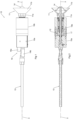
- a sprayer according to the invention adapted to apply a fluid to an inner surface of a tubular element, is indicated as a whole with the number 10 and is clearly visible in Figures 1, 2 and 5 .
- This sprayer 10 comprises:
- the diffusion bell 11 has its concavity in a position distal to the supporting body 16a and 16b.
- the diffusion bell 11 has its own concavity oriented in the direction of the supporting body 16a and 16b, still falling within the protective scope of the present invention.
- the diffusion bell 11 comprises a truncated-cone body 11b and a containment element 14 attached to said inner surface of the diffusion bell 11 so as to form a fluid storage compartment, as it can be inferred from the Figures 1, 2 , 3 and 5 .
- the pipe 13 faces the inner surface of the containment element 14 and the diffusion bell 11 shows at least one slit 15 defined between the truncated-cone body 11b and the containment element 14 to allow the diffusion of said fluid when the diffusion bell 11 is placed in rotation by the rotation means 12.
- This containment element 14 and these three slits 15 make it advantageously possible to obtain a better atomisation of the aforesaid fluid.
- this containment element 14 is convex with respect to said inner surface of said truncated-cone body 11b, but it cannot be excluded that the containment element 14 is flat in various embodiments of the invention.
- the slits 15 are in a number other than the one described in the present embodiment of the invention.
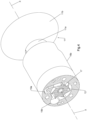
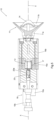
- the rotation means 12 comprise a turbine 17, clearly visible in Figures 2 , 4 and 5 , which is rotatably constrained within the supporting body 16a and 16b coaxially to the axis of symmetry X of the diffusion bell 11.
- the aforesaid turbine 17 is operatively connected to the base 11a of the diffusion bell 11 and is configured to be rotated by a compressed air circuit 18, where the use of the turbine 17 and of the circuit 18 advantageously allow the structure of the sprayer 10 to be made even more compact.
- the supporting body 16a and 16b comprises an inlet channel 18a and an outlet channel 18b of the circuit 18, both visible in Figures 1 and 5 .
- the supporting body 16a and 16b has an inlet groove 19a, clearly shown in Figure 4 , connected to the inlet channel 18a and defined at the plane in which the turbine 17 lies orthogonally to the axis of symmetry X.
- this inlet groove 19a is configured to make the air flow tangentially to the turbine 17 and then towards the aforementioned outlet channel 18b.
- This inlet groove 19a allows the compressed air conveyed by the inlet channel 18a to be accelerated, causing the turbine 17 to rotate at high speeds much faster than similar known-type sprayers.
- the supporting body 16a and 16b also has an outlet groove 19b, also shown in Figure 4 , connected to the outlet channel 18b and defined in the same plane as the inlet groove 19a.
- the inlet groove 19a has an angle of curvature greater than 90°.
- this inlet groove 19a has a substantially C-shaped profile.
- the sprayer 10 also comprises rotation detecting means 20, clearly visible in Figure 5 , configured to detect the instantaneous rotation speed of the rotation means 12 and operationally connected to the circuit 18 so as to define a feedback control of the flow of compressed air towards the turbine 17.
- the detecting means 20 comprise at least one permanent magnet fixed integrally to the rotation means 12 and configured to generate a magnetic field in a substantially radial direction with respect to the longitudinal development of said rotation means 12.
- the detecting means 20 comprise at least one winding coupled with the aforesaid permanent magnet and adapted to convert a portion of the mechanical power associated with the rotation means 12 into electrical power for powering the electronics of the detecting means 20.
- the detecting means 20 still comprise a wireless transmission module configured to transmit to an external receiving device data related to the rotation speed.
- the wireless transmission module is also powered by the aforesaid winding.
- no wiring is required to power the electronics of the detecting means 20 and to transmit the aforesaid data related to the rotation speed, which is typically difficult in the context of spraying tubular elements with particularly long longitudinal development.
- the sprayer 10 comprises an electromechanical unit to adjust the aforesaid flow of compressed air towards the turbine 17.
- this electromechanical adjustment unit comprises an electric motor and an adjustment valve configured to act on the flow of compressed air towards the turbine 17 based on the data related to the rotation speed.
Landscapes
- Engineering & Computer Science (AREA)
- Mechanical Engineering (AREA)
- General Engineering & Computer Science (AREA)
- Electrostatic Spraying Apparatus (AREA)
- Nozzles (AREA)
Applications Claiming Priority (1)
| Application Number | Priority Date | Filing Date | Title |
|---|---|---|---|
| IT102023000010713A IT202300010713A1 (it) | 2023-05-26 | 2023-05-26 | Spruzzatore per l’applicazione di un fluido su una superficie interna di un elemento tubolare |
Publications (1)
| Publication Number | Publication Date |
|---|---|
| EP4470672A1 true EP4470672A1 (de) | 2024-12-04 |
Family
ID=87801625
Family Applications (1)
| Application Number | Title | Priority Date | Filing Date |
|---|---|---|---|
| EP24177727.5A Pending EP4470672A1 (de) | 2023-05-26 | 2024-05-23 | Zerstäuber zum aufbringen eines fluids auf die innenfläche eines rohrförmigen elements |
Country Status (2)
| Country | Link |
|---|---|
| EP (1) | EP4470672A1 (de) |
| IT (1) | IT202300010713A1 (de) |
Citations (9)
| Publication number | Priority date | Publication date | Assignee | Title |
|---|---|---|---|---|
| US3233580A (en) * | 1962-11-05 | 1966-02-08 | Plastic Materials Inc | Material mixing and applying apparatus |
| EP0224052A2 (de) * | 1985-11-22 | 1987-06-03 | Binks Manufacturing Company | Reinigungsfreundlicher Zerstäuber |
| EP0250942A2 (de) * | 1986-06-26 | 1988-01-07 | Illinois Tool Works Inc. | Rotierender Zerstäuber mit Luftlager |
| US4723726A (en) * | 1985-06-11 | 1988-02-09 | Toyota Jidosha Kabushiki Kaisha | Rotating speed control device of a rotary type electrostatic spray painting device |
| DE102004032045A1 (de) * | 2004-07-02 | 2006-01-26 | J. Wagner Ag | Rotationszerstäuber |
| EP1789199A1 (de) * | 2004-09-03 | 2007-05-30 | GSI Group Limited | Antriebsspindel |
| US20070145250A1 (en) * | 2002-09-02 | 2007-06-28 | Michael Baumann | Sensor arrangement for a coating system |
| US20120048196A1 (en) * | 2009-02-09 | 2012-03-01 | Sames Technologies | Electrostatic projector comprising a rotation speed detection device |
| WO2022157098A1 (de) * | 2021-01-19 | 2022-07-28 | Dürr Systems Ag | Beschichtungseinrichtung, insbesondere rotationszerstäuber |
-
2023
- 2023-05-26 IT IT102023000010713A patent/IT202300010713A1/it unknown
-
2024
- 2024-05-23 EP EP24177727.5A patent/EP4470672A1/de active Pending
Patent Citations (9)
| Publication number | Priority date | Publication date | Assignee | Title |
|---|---|---|---|---|
| US3233580A (en) * | 1962-11-05 | 1966-02-08 | Plastic Materials Inc | Material mixing and applying apparatus |
| US4723726A (en) * | 1985-06-11 | 1988-02-09 | Toyota Jidosha Kabushiki Kaisha | Rotating speed control device of a rotary type electrostatic spray painting device |
| EP0224052A2 (de) * | 1985-11-22 | 1987-06-03 | Binks Manufacturing Company | Reinigungsfreundlicher Zerstäuber |
| EP0250942A2 (de) * | 1986-06-26 | 1988-01-07 | Illinois Tool Works Inc. | Rotierender Zerstäuber mit Luftlager |
| US20070145250A1 (en) * | 2002-09-02 | 2007-06-28 | Michael Baumann | Sensor arrangement for a coating system |
| DE102004032045A1 (de) * | 2004-07-02 | 2006-01-26 | J. Wagner Ag | Rotationszerstäuber |
| EP1789199A1 (de) * | 2004-09-03 | 2007-05-30 | GSI Group Limited | Antriebsspindel |
| US20120048196A1 (en) * | 2009-02-09 | 2012-03-01 | Sames Technologies | Electrostatic projector comprising a rotation speed detection device |
| WO2022157098A1 (de) * | 2021-01-19 | 2022-07-28 | Dürr Systems Ag | Beschichtungseinrichtung, insbesondere rotationszerstäuber |
Also Published As
| Publication number | Publication date |
|---|---|
| IT202300010713A1 (it) | 2024-11-26 |
Similar Documents
| Publication | Publication Date | Title |
|---|---|---|
| US20220149695A1 (en) | Actuator | |
| US20170094185A1 (en) | Gimbal driving device and gimbal assembly using the same | |
| US5617762A (en) | Miniature positioning device | |
| US20180003103A1 (en) | Wastegate actuator and wastegate valve driving device | |
| US10556352B2 (en) | Waist rotation structure and robot | |
| EP3422138B1 (de) | Bedienungsvorrichtung | |
| EP4470672A1 (de) | Zerstäuber zum aufbringen eines fluids auf die innenfläche eines rohrförmigen elements | |
| US20230204971A1 (en) | Multi-axis sector motor | |
| EP3439153A1 (de) | Drehstellantrieb und roboter | |
| US20140186199A1 (en) | Electric blower | |
| US20170192342A1 (en) | Camera apparatus | |
| EP4418458A3 (de) | Antennenvorrichtung | |
| US20140354118A1 (en) | Encoder for a compact revolution transmitter and electric motor with a compact revolution transmitter | |
| EP3940285A1 (de) | Winkelanpassungsvorrichtung, sensoranordnung und unbemanntes automobil | |
| EP3018798A1 (de) | Motor und klimatisierungsvorrichtung | |
| JP6271268B2 (ja) | 電動送風機およびその製造方法 | |
| US20100037720A1 (en) | Robotic manipulator | |
| US20220018891A1 (en) | Adjustable anchor for printed circuit board environmental sensor | |
| EP4184709B1 (de) | Automatisches strahllenkungssystem für eine reflektorantenne | |
| US6872013B2 (en) | Iris with integrated drive motor | |
| JPWO2018092649A1 (ja) | アクチュエータ及びカメラ装置 | |
| KR101544936B1 (ko) | 전선 길이가 가변되는 회전형 커넥터 및 전기 접속 시스템 | |
| CN105356061A (zh) | 一种天线螺旋面分区限位及数据发送一体化装置 | |
| US11493137B1 (en) | Monoplanar iris diaphragm | |
| EP3441656A1 (de) | Verstellbare verbindung mit rückschlagventil |
Legal Events
| Date | Code | Title | Description |
|---|---|---|---|
| PUAI | Public reference made under article 153(3) epc to a published international application that has entered the european phase |
Free format text: ORIGINAL CODE: 0009012 |
|
| STAA | Information on the status of an ep patent application or granted ep patent |
Free format text: STATUS: THE APPLICATION HAS BEEN PUBLISHED |
|
| AK | Designated contracting states |
Kind code of ref document: A1 Designated state(s): AL AT BE BG CH CY CZ DE DK EE ES FI FR GB GR HR HU IE IS IT LI LT LU LV MC ME MK MT NL NO PL PT RO RS SE SI SK SM TR |
|
| STAA | Information on the status of an ep patent application or granted ep patent |
Free format text: STATUS: REQUEST FOR EXAMINATION WAS MADE |
|
| 17P | Request for examination filed |
Effective date: 20250401 |