EP4470723A1 - Outil de frappe - Google Patents
Outil de frappe Download PDFInfo
- Publication number
- EP4470723A1 EP4470723A1 EP24176269.9A EP24176269A EP4470723A1 EP 4470723 A1 EP4470723 A1 EP 4470723A1 EP 24176269 A EP24176269 A EP 24176269A EP 4470723 A1 EP4470723 A1 EP 4470723A1
- Authority
- EP
- European Patent Office
- Prior art keywords
- handle
- striking
- sheath
- segment
- connecting rod
- Prior art date
- Legal status (The legal status is an assumption and is not a legal conclusion. Google has not performed a legal analysis and makes no representation as to the accuracy of the status listed.)
- Pending
Links
Images




Classifications
-
- B—PERFORMING OPERATIONS; TRANSPORTING
- B25—HAND TOOLS; PORTABLE POWER-DRIVEN TOOLS; MANIPULATORS
- B25D—PERCUSSIVE TOOLS
- B25D1/00—Hand hammers; Hammer heads of special shape or materials
- B25D1/04—Hand hammers; Hammer heads of special shape or materials with provision for withdrawing or holding nails or spikes
-
- B—PERFORMING OPERATIONS; TRANSPORTING
- B25—HAND TOOLS; PORTABLE POWER-DRIVEN TOOLS; MANIPULATORS
- B25D—PERCUSSIVE TOOLS
- B25D1/00—Hand hammers; Hammer heads of special shape or materials
- B25D1/12—Hand hammers; Hammer heads of special shape or materials having shock-absorbing means
-
- B—PERFORMING OPERATIONS; TRANSPORTING
- B25—HAND TOOLS; PORTABLE POWER-DRIVEN TOOLS; MANIPULATORS
- B25G—HANDLES FOR HAND IMPLEMENTS
- B25G1/00—Handle constructions
- B25G1/02—Handle constructions flexible
-
- B—PERFORMING OPERATIONS; TRANSPORTING
- B25—HAND TOOLS; PORTABLE POWER-DRIVEN TOOLS; MANIPULATORS
- B25G—HANDLES FOR HAND IMPLEMENTS
- B25G1/00—Handle constructions
- B25G1/10—Handle constructions characterised by material or shape
-
- B—PERFORMING OPERATIONS; TRANSPORTING
- B25—HAND TOOLS; PORTABLE POWER-DRIVEN TOOLS; MANIPULATORS
- B25G—HANDLES FOR HAND IMPLEMENTS
- B25G1/00—Handle constructions
- B25G1/10—Handle constructions characterised by material or shape
- B25G1/102—Handle constructions characterised by material or shape the shape being specially adapted to facilitate handling or improve grip
Definitions
- the present invention relates to a striking tool, in particular a striking tool with vibration reduction functionality.
- Striking tools such as claw hammers and sledgehammers have a broad range of uses in industry and everyday life, and generally include a hammer head and a handle extending from the hammer head.
- a user can grip a remote end of the handle and swing the hammer head to strike a target object.
- the reaction force acting on the hammer head from the target object is substantially perpendicular to the longitudinal direction of the handle, causing the handle to vibrate. This vibration is then transmitted to the user through the hand gripping the handle, causing the user sharp discomfort.
- striking work is also liable to cause pathological injury to the joints, bones or muscles of the hand, shoulder or other places, harming the user's physical health.
- An object of the present invention is to provide a striking tool with vibration reduction functionality, to alleviate the discomfort which striking causes to the user.
- the striking tool comprises:
- the flexible segment has a shorter length than the rigid segment, and the ratio of the length of the rigid segment to the length of the flexible segment is in the range of 4 - 10, preferably 6-8, and is more preferably 7.
- the handle comprises:
- the connecting rod is made of a first material
- the sheath is made of a second material, the second material having a lower hardness than the first material
- the first material is preferably metal, in particular steel
- the second material is preferably hard plastic, in particular polypropylene.
- a counterweight is provided at the distal end of the sheath.
- an end opening is formed at the distal end of the sheath, and the counterweight is constructed as a plug which blocks the end opening; the counterweight is made of metal material, in particular copper or brass.
- the counterweight has a thickness of 5 - 11 mm in the direction of extension of the handle; preferably, the thickness of the counterweight is 7% - 40%, preferably 15% - 30%, and more preferably about 20% of the length of the flexible segment.
- an elastic member is provided in the cavity; preferably, the elastic member is constructed as a spring, and/or an elastomeric material filling the cavity.
- the handle further comprises a cover which encases and covers the sheath, the cover being made of a third material, the third material having a lower hardness than a material forming the sheath, and the third material preferably being thermoplastic rubber material.
- the sheath is covered with the cover by an overmoulding process.
- the material forming the cover also fills the cavity formed at the distal end of the sheath, to form an elastic member arranged in the cavity.
- the handle further comprises a filling member, the filling member being arranged between the connecting rod and the sheath in a direction perpendicular to the direction of extension of the handle, and the filling member being made of a fourth material, the fourth material having a lower hardness than a material forming the sheath.
- the fourth material is thermoplastic rubber material.
- the filling member has a sheath-like structure, at least a part of the connecting rod being accommodated in the sheath-like structure.
- the material forming the filling member also fills the cavity formed at the distal end of the sheath, to form an elastic member arranged in the cavity.
- the filling member and the elastic member are integrally formed.
- the connecting rod is provided with a weight reduction hole.
- the handle further comprises a fastener, the fastener passing through the sheath and being connected and fixed to the connecting rod.
- the sheath comprises a proximal segment and a distal segment which are arranged discretely and spaced apart in the direction of extension of the handle.
- a gripping prevention part adjacent to the gripping part is provided on the handle at a position corresponding to that end of the flexible segment which is connected to the rigid segment, the gripping prevention part having a larger dimension than the gripping part in a direction perpendicular to the direction of extension of the handle.
- the gripping prevention part has a length not less than 33 mm in the direction of extension of the handle, and/or the gripping prevention part has a dimension not less than 42.5 mm in a direction perpendicular to the direction of extension of the handle.
- a striking tool comprising:
- the gripping part for a user to grip on the handle thereof is arranged to correspond to one the nodes of vibration formed on the handle during striking, hence the position where the user grips has the smallest vibration amplitude, and the energy of vibration transmitted through the handle to the user's hand and arm is also smallest, thus alleviating the adverse effects of vibration.
- the present invention provides a striking tool, which specifically may be in the form of a hammer, such as a claw hammer.
- a striking tool according to the present invention is described below with reference to the drawings.
- a striking tool 1 may comprise a striking head 10 and a handle 20.
- the striking head 10 may also be called a hammer head.
- One end of the striking head 10 is provided with a striking part 11, which has a substantially flat or outwardly protruding end face, for performing striking tasks.
- a direction in which a user swings the striking tool 1 to make the striking head 10 move towards a target object to be struck may be called the striking direction, shown as D1 in Fig. 1 .
- An end of the striking head 10 opposite the striking part 11 is provided with a forked part 12, which comprises two legs spaced apart from each other, with a substantially V-shaped opening formed between the two legs. An end of a nail can be engaged in the opening, to pull out the nail.
- the handle 20 is connected to the striking head 10, and extends substantially transversely to the striking direction D1 of the striking head 10.
- the direction of extension of the handle 20 is shown as D2 in Fig. 1 .
- the end of the handle 20 that faces the striking head 10 is called the "proximal end", and the end of the handle 20 that is remote from the striking head 10 is called the “distal end”.
- the components mentioned below that form the handle 20 follow the same definition of directions.
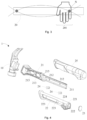
- the handle 20 is connected by its proximal end to the striking head 10. Specifically, as shown in Fig. 2 , the striking head 10 is provided with a mounting protrusion 13 and a first mounting hole 14.
- the proximal end of the handle 20 is provided with a mounting recess 204 adapted to the shape of the mounting protrusion 13, and is also provided with a second mounting hole 205.
- the striking head 10 is connected to the handle 20 through engagement of the mounting protrusion 13 in the mounting recess 204, while the first mounting hole 14 is aligned with the second mounting hole 205, and a fastener such as a screw can then be fixed in the first mounting hole 14 and the second mounting hole 205, to prevent loosening of the striking head 10.
- connection may also be used for connecting the striking head to the handle.
- the proximal end of the handle is configured as a columnar structure, while a mounting through-hole adapted thereto is provided on the striking head, and the columnar structure is engaged in the mounting through-hole, or a threaded structure is provided to screw into the mounting through-hole to realize the connection, and the firmness of the connection can be increased by adding friction material or welding, etc.; or the striking head and handle may be connected directly by welding, or the striking head and handle may be integrally injection moulded.
- the handle 20 forms a gripping part 201 for the user to grip.
- the striking head 10 strikes the target object, and at the same time, the target object applies a reaction force to the striking head 10, causing vibration.
- the direction of the reaction force is substantially in the striking direction D1, i.e. substantially perpendicular to the direction of extension D2 of the handle 20.
- the handle 20 may be regarded as an elongated rod extending in direction D2.
- the vibration in the handle 20 caused by the reaction force may be regarded as a transverse wave propagating from the proximal end of the handle 20 towards the distal end thereof. As shown schematically in Fig.
- the handle 20 in the process of transverse wave transmission, there is a position of minimum (or zero) vibration amplitude, and this position is called a vibration node (N), or may also be called a wave node.
- the handle 20 is constructed such that one of the vibration nodes N of the vibration (i.e. transverse wave) in the handle 20 caused by the reaction force applied by the target object is located at the gripping part 201. In this way, the user's hand that grips the handle 20 experiences the vibration with the smallest amplitude, so the adverse effects of vibration are alleviated.
- the handle 20 is configured to comprise two parts: a rigid segment 206 and a flexible segment 207.
- the rigid segment 206 has a first rigidity
- the flexible segment 207 has a second rigidity less than the first rigidity.
- the striking head 10 is mounted at the proximal end of the rigid segment 206.
- the rigid segment 206 has higher rigidity, and can thus provide full rigid support to the striking head 10, so as to meet the needs of striking work.
- the flexible segment 207 is connected to the distal end of the rigid segment 206.
- the gripping part 201 is disposed at a position on the handle 20 that corresponds to the distal end of the rigid segment 206.
- the flexible segment 207 has lower rigidity, and experiences more vibration than the rigid segment 206; consequently, the distal end of the rigid segment 206 can have a smaller vibration amplitude, so as to form a vibration node.
- the length of the flexible segment 207 is set to be smaller, or much smaller, than the length of the rigid segment 206.
- the ratio of the length of the rigid segment 206 to the length of the flexible segment 207 is 4 - 10, preferably 6-8, and more preferably 7.
- rigid segment and “flexible segment” are intended to make clear that there is a difference in rigidity between the two parts of the handle, but are not used to limit characteristics of the two parts other than rigidity.
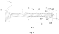
- the handle 20 comprises a connecting rod 21 and a sheath 22, which both have a substantially elongated structure.
- the connecting rod 21 is for connecting to the striking head 10. That is, the structure for connecting to the striking head 10, including the mounting recess 204 and the second mounting hole 205, is arranged on the connecting rod 21, specifically at the proximal end thereof. It can be seen from a distal end 211 of the connecting rod 21 that the cross section of the connecting rod 21 perpendicular to the longitudinal direction thereof is substantially constructed as an H-shaped structure. Such a structure has good force-bearing characteristics, and is able to meet the force-bearing demands of striking. Furthermore, the connecting rod 21 is also provided with weight reduction holes 213 at positions close to the proximal end thereof, which can reduce the overall mass of the striking tool 1 while ensuring structural strength, so that less effort is required.
- the sheath 22 is fitted round the connecting rod 21, and covers the distal end 211 of the connecting rod 21. Furthermore, the distal end 211 of the connecting rod 21 is separated from a distal end 221 of the sheath 22 by a predetermined distance, so that a cavity 203 is formed inside the sheath 22 at a position between the distal end 211 of the connecting rod 21 and the distal end 221 of the sheath 22. That is, the distal end of the handle 20 is formed as a hollow structure.
- the hollow configuration can reduce the mass of this structural segment, helping to transfer vibration from the gripping part 201 to a position further towards the rear of the handle 20. It can be seen from Fig. 1 that a part of the handle 20 corresponding to the connecting rod 21 is formed as the rigid segment 206, and a part of the handle 20 corresponding to the cavity 203 is formed as the flexible segment 207.
- the connecting rod 21 may be made of a material having higher hardness and rigidity, so as to meet the requirements of striking with the striking tool 1.
- the material from which the connecting rod 21 is made may be metal, in particular steel.
- the sheath 22 may be made of a material having a lower hardness than the connecting rod 21. That is, the sheath 22 is softer than the connecting rod 21.
- the material from which the sheath 22 is made may be hard plastic, in particular polypropylene (PP). Making the sheath 22 from a softer material than the connecting rod 21 helps to transfer vibration from the gripping part 201 to another position.
- a counterweight 23 is provided at the distal end of the handle 20. Having configured the part between the distal end 211 of the connecting rod 21 and the distal end 221 of the sheath 22 to be hollow to reduce the mass of this structural segment, further providing the counterweight 23 at the distal end of the handle 20 can also promote the transfer of vibration from the gripping part 201.
- the distal end 221 of the sheath 22 substantially forms the distal end of the handle 20.
- end opening 222 is formed in the distal end 221 of the sheath 22, and the counterweight 23 is constructed as a plug which is attached to the sheath 22 and blocks the end opening 222.
- the counterweight 23 may be made of metal, e.g. copper or brass, etc.
- the thickness T of the counterweight 23 in the direction of extension D2 of the handle 20 is set to be 5 - 11 mm, so that the counterweight 23 does not adversely affect the hollow structure between the distal end 211 of the connecting rod 21 and the distal end 221 of the sheath 22.
- the thickness of the counterweight 23 is 7% - 40%, preferably 15% - 30%, more preferably about 20%, of the length of the flexible segment 207.
- a gripping prevention part 202 is provided at the distal end of the handle 20; this may be arranged at a position corresponding to that end of the flexible segment 207 which is connected to the rigid segment 206, and specifically may be realized by increasing a radial dimension of the gripping prevention part 202, such that the gripping prevention part 202 is less easily gripped than the gripping part 201.
- the length of extension L1 of the gripping prevention part 202 may be set to be not less than 33 mm.
- the gripping prevention part 202 may have a maximum radial dimension L2, which may be set to be not less than 42.5 mm, at a position adjacent to the gripping part 201.
- a placement region 227 for placing the little finger may also be formed on the gripping part 201 at a position close to the maximum radial dimension of the gripping prevention part 202.
- the handle 20 is also provided with a cover 25 which encases and covers the sheath 22.
- the cover 25 is made of a material having a lower hardness than the sheath 22, i.e. the cover 25 is softer than the sheath 22.
- the material from which the cover 25 is made may be thermoplastic rubber material (TPR). This type of material allows the cover 25 to be directly made and shaped on the outside of the sheath 22 by overmoulding.
- an elastic member 26 may also be provided in the cavity 203, to absorb vibration.
- the elastic member 26 may be obtained by filling the cavity 203 with an elastomeric material.
- the material of the cover 25 is soft, does not affect mass much, and has good elasticity, so the material from which the cover 25 is formed may be used to fill the cavity 203, so as to form the elastic member 26.
- an injection moulding hole 224 is provided on the sheath 22 at a position corresponding to the cavity 203.
- the striking tool 1 shown in the drawings may be assembled by the following steps. Firstly, the striking head 10 and the connecting rod 21 which have been made and shaped are connected. The distal end 211 of the connecting rod 21 is then inserted into the sheath 22. At the same time, the counterweight 23 is attached to the end opening 23 of the sheath 22. The cover 25 can then be made and shaped on the sheath 22 directly by overmoulding, while filling the cavity 203 with the same material as the cover 25 via the injection moulding hole 224.
- a stop part 215 may be provided in a middle part of the connecting rod 21, and the proximal end of the sheath 22 abuts the stop part 215.
- the connecting rod 21 and the sheath 22 may be accurately fixed. Furthermore, the connecting rod 21 and the sheath 22 may be further securely connected by means of fasteners 24 such as rivets.
- fasteners 24 such as rivets.
- third mounting holes 212 are provided in a part of the connecting rod 21 that is inserted into the sheath 22, and fourth mounting holes 223 are provided at corresponding positions on the sheath 22. After fitting the sheath 22 in place but before making the cover 25, the fasteners 24 may be passed through the aligned third mounting holes 212 and fourth mounting holes 223, to fasten the connecting rod 21 to the sheath 22.
- Figs. 6-9 show striking tools according to other embodiments of the present invention.
- the structures therein are largely the same as the structure of the striking tool 1 shown in Figs. 1-5 , and shown with the same reference labels.
- the sheath 22' is constructed as a split structure formed of two parts, comprising a proximal segment 225 and a distal segment 226, which are separated from one another in the direction of extension of the handle 20. Furthermore, weight reduction holes 214 are also provided in the part of the connecting rod 21 that is disposed within the sheath 22'. In addition, it will be understood that the cover is omitted in Fig. 6 , so as to better show the split structure of the sheath 22'.
- an elastic body 26' located in the cavity 203 of the handle 20 is formed of a spring, and specifically may be a suitable spring in any form such as a coil spring or a spring plate. It is connected at one end to the distal end 211 of the connecting rod 21, and at the other end to the counterweight 23 blocking the cavity 203.
- an elastic body may also be formed through a combination of a spring and filling with an elastomeric material; for example, a spring structure is first arranged in the cavity 203, and then the cavity is filled with an elastomeric material.
- the striking head 10 and the connecting rod 21 of the handle 20 are integrally formed.
- the cover 25 is a split member formed of two parts which respectively cover an upper part and a lower part of the sheath 22.
- the distal end 221 of the sheath 22 is constructed as a closed structure.
- the counterweight 23 may be arranged in the sheath 22, abutting an inside wall of the distal end 221.
- the striking tool 4 further comprises a filling member 27, which is arranged between the connecting rod 21 and the sheath 22 in a direction perpendicular to the direction of extension of the handle 20.
- the filling member 27 may have a sheath-like structure. At least a part of the connecting rod 21 extends into the sheath-like structure. The connecting rod 21 and the sheath-like structure are then extended into the sheath 22 together.
- the filling member 27 may be made of a material having a lower hardness than the sheath 22, i.e. the filling member 27 is softer than the sheath 22.
- the material from which the filling member 27 is made may be thermoplastic rubber material (TPR).
- the cavity 203 may be filled with the material from which the filling member 27 is formed, so as to form the elastic member 26.
- the filling member 27 and the elastic member 26 may be formed as an integral structure.
Landscapes
- Engineering & Computer Science (AREA)
- Mechanical Engineering (AREA)
- Percussive Tools And Related Accessories (AREA)
- Percussion Or Vibration Massage (AREA)
Applications Claiming Priority (1)
| Application Number | Priority Date | Filing Date | Title |
|---|---|---|---|
| CN202310640158.4A CN119057738A (zh) | 2023-05-31 | 2023-05-31 | 敲击工具 |
Publications (1)
| Publication Number | Publication Date |
|---|---|
| EP4470723A1 true EP4470723A1 (fr) | 2024-12-04 |
Family
ID=91129421
Family Applications (1)
| Application Number | Title | Priority Date | Filing Date |
|---|---|---|---|
| EP24176269.9A Pending EP4470723A1 (fr) | 2023-05-31 | 2024-05-16 | Outil de frappe |
Country Status (5)
| Country | Link |
|---|---|
| US (1) | US20240399557A1 (fr) |
| EP (1) | EP4470723A1 (fr) |
| CN (1) | CN119057738A (fr) |
| AU (1) | AU2024203237A1 (fr) |
| TW (1) | TW202448644A (fr) |
Citations (9)
| Publication number | Priority date | Publication date | Assignee | Title |
|---|---|---|---|---|
| US5911795A (en) * | 1997-10-15 | 1999-06-15 | The Stanley Works | Hammer with vibration damper and method of making same |
| US20120152066A1 (en) * | 2010-12-21 | 2012-06-21 | Fiskars France Sas | Hand-operated striking tool enabling vibrations to be reduced, and method for manufacturing |
| EP2743037A2 (fr) * | 2012-12-14 | 2014-06-18 | Stanley Black & Decker, Inc. | Marteau à amortissement de vibrations |
| EP2848372A2 (fr) * | 2013-09-12 | 2015-03-18 | Stanley Black & Decker, Inc. | Marteau avec poignée rigide |
| US20160008966A1 (en) * | 2014-07-14 | 2016-01-14 | Fiskars Brands, Inc. | Vibration reduction mechanism for a striking tool |
| EP3075493A1 (fr) * | 2015-03-31 | 2016-10-05 | Fiskars Brands, Inc. | Motif à prise par frottement variable |
| US20190255691A1 (en) * | 2018-02-21 | 2019-08-22 | Milwaukee Electric Tool Corporation | Hammer |
| US20190283226A1 (en) * | 2016-11-30 | 2019-09-19 | Hangzhou Great Star Industrial Co., Ltd. | A handle and a hammering tool |
| WO2022164852A1 (fr) * | 2021-01-27 | 2022-08-04 | Apex Brands, Inc. | Outil de frappe doté d'une prise antichoc |
-
2023
- 2023-05-31 CN CN202310640158.4A patent/CN119057738A/zh active Pending
-
2024
- 2024-05-13 TW TW113117559A patent/TW202448644A/zh unknown
- 2024-05-15 AU AU2024203237A patent/AU2024203237A1/en active Pending
- 2024-05-16 EP EP24176269.9A patent/EP4470723A1/fr active Pending
- 2024-05-24 US US18/673,802 patent/US20240399557A1/en active Pending
Patent Citations (9)
| Publication number | Priority date | Publication date | Assignee | Title |
|---|---|---|---|---|
| US5911795A (en) * | 1997-10-15 | 1999-06-15 | The Stanley Works | Hammer with vibration damper and method of making same |
| US20120152066A1 (en) * | 2010-12-21 | 2012-06-21 | Fiskars France Sas | Hand-operated striking tool enabling vibrations to be reduced, and method for manufacturing |
| EP2743037A2 (fr) * | 2012-12-14 | 2014-06-18 | Stanley Black & Decker, Inc. | Marteau à amortissement de vibrations |
| EP2848372A2 (fr) * | 2013-09-12 | 2015-03-18 | Stanley Black & Decker, Inc. | Marteau avec poignée rigide |
| US20160008966A1 (en) * | 2014-07-14 | 2016-01-14 | Fiskars Brands, Inc. | Vibration reduction mechanism for a striking tool |
| EP3075493A1 (fr) * | 2015-03-31 | 2016-10-05 | Fiskars Brands, Inc. | Motif à prise par frottement variable |
| US20190283226A1 (en) * | 2016-11-30 | 2019-09-19 | Hangzhou Great Star Industrial Co., Ltd. | A handle and a hammering tool |
| US20190255691A1 (en) * | 2018-02-21 | 2019-08-22 | Milwaukee Electric Tool Corporation | Hammer |
| WO2022164852A1 (fr) * | 2021-01-27 | 2022-08-04 | Apex Brands, Inc. | Outil de frappe doté d'une prise antichoc |
Also Published As
| Publication number | Publication date |
|---|---|
| CN119057738A (zh) | 2024-12-03 |
| US20240399557A1 (en) | 2024-12-05 |
| AU2024203237A1 (en) | 2024-12-19 |
| TW202448644A (zh) | 2024-12-16 |
Similar Documents
| Publication | Publication Date | Title |
|---|---|---|
| EP1894681B1 (fr) | Outil d'impact fonctionnant manuellement et procédé de fabrication d'un outil d'impact à fonctionnement manuel | |
| US6755096B2 (en) | Impact instrument | |
| US6202511B1 (en) | Vibration damped hammer | |
| US7261641B2 (en) | Method and apparatus for improving dynamic response of golf club | |
| US4331193A (en) | Flexible handle for percussive tool employing improved shaft member | |
| US9233462B2 (en) | Hammer | |
| US20170211646A1 (en) | Force-limiting and Damping Device | |
| JP5645057B2 (ja) | 軽量ハンドグリップ及びその製造方法 | |
| US6158307A (en) | Shock absorption system for a striking tool | |
| US10093014B2 (en) | Auxiliary handle | |
| US20020058557A1 (en) | Dynamic damper and dynamic damper-installed tennis racket | |
| EP4470723A1 (fr) | Outil de frappe | |
| AU2022214088B2 (en) | Striking implement with anti-shock grip | |
| EP1283092A1 (fr) | Amortisseur intégré pour marteau et méthode | |
| US20110119853A1 (en) | Scraper | |
| US4266588A (en) | Flexible handle for percussive tool with improved vertebra member | |
| JP2015221191A (ja) | 顔面筋鍛錬具 | |
| CN222405544U (zh) | 一种带有减震功能的锤子 | |
| CN223863712U (zh) | 一种减震钛合金连体羊角锤 | |
| US20190314974A1 (en) | Ergonomic hand tool | |
| KR200349334Y1 (ko) | 완충용 손잡이를 갖는 타악기용 채 | |
| WO2022185059A1 (fr) | Accessoire pour entraînement physique | |
| KR20100012503U (ko) | 탄성이 구비된 망치 | |
| JP2015221199A (ja) | 顔面筋鍛錬具 |
Legal Events
| Date | Code | Title | Description |
|---|---|---|---|
| PUAI | Public reference made under article 153(3) epc to a published international application that has entered the european phase |
Free format text: ORIGINAL CODE: 0009012 |
|
| STAA | Information on the status of an ep patent application or granted ep patent |
Free format text: STATUS: THE APPLICATION HAS BEEN PUBLISHED |
|
| AK | Designated contracting states |
Kind code of ref document: A1 Designated state(s): AL AT BE BG CH CY CZ DE DK EE ES FI FR GB GR HR HU IE IS IT LI LT LU LV MC ME MK MT NL NO PL PT RO RS SE SI SK SM TR |
|
| STAA | Information on the status of an ep patent application or granted ep patent |
Free format text: STATUS: REQUEST FOR EXAMINATION WAS MADE |
|
| 17P | Request for examination filed |
Effective date: 20250603 |