EP4470732A1 - Robot équipé d'un capteur lidar et son procédé de commande - Google Patents
Robot équipé d'un capteur lidar et son procédé de commande Download PDFInfo
- Publication number
- EP4470732A1 EP4470732A1 EP23846754.2A EP23846754A EP4470732A1 EP 4470732 A1 EP4470732 A1 EP 4470732A1 EP 23846754 A EP23846754 A EP 23846754A EP 4470732 A1 EP4470732 A1 EP 4470732A1
- Authority
- EP
- European Patent Office
- Prior art keywords
- electronic device
- mirror
- light
- sensor
- robot
- Prior art date
- Legal status (The legal status is an assumption and is not a legal conclusion. Google has not performed a legal analysis and makes no representation as to the accuracy of the status listed.)
- Pending
Links
Images






Classifications
-
- G—PHYSICS
- G01—MEASURING; TESTING
- G01S—RADIO DIRECTION-FINDING; RADIO NAVIGATION; DETERMINING DISTANCE OR VELOCITY BY USE OF RADIO WAVES; LOCATING OR PRESENCE-DETECTING BY USE OF THE REFLECTION OR RERADIATION OF RADIO WAVES; ANALOGOUS ARRANGEMENTS USING OTHER WAVES
- G01S17/00—Systems using the reflection or reradiation of electromagnetic waves other than radio waves, e.g. lidar systems
- G01S17/88—Lidar systems specially adapted for specific applications
- G01S17/93—Lidar systems specially adapted for specific applications for anti-collision purposes
- G01S17/931—Lidar systems specially adapted for specific applications for anti-collision purposes of land vehicles
-
- B—PERFORMING OPERATIONS; TRANSPORTING
- B25—HAND TOOLS; PORTABLE POWER-DRIVEN TOOLS; MANIPULATORS
- B25J—MANIPULATORS; CHAMBERS PROVIDED WITH MANIPULATION DEVICES
- B25J13/00—Controls for manipulators
- B25J13/08—Controls for manipulators by means of sensing devices, e.g. viewing or touching devices
- B25J13/088—Controls for manipulators by means of sensing devices, e.g. viewing or touching devices with position, velocity or acceleration sensors
-
- B—PERFORMING OPERATIONS; TRANSPORTING
- B25—HAND TOOLS; PORTABLE POWER-DRIVEN TOOLS; MANIPULATORS
- B25J—MANIPULATORS; CHAMBERS PROVIDED WITH MANIPULATION DEVICES
- B25J13/00—Controls for manipulators
- B25J13/08—Controls for manipulators by means of sensing devices, e.g. viewing or touching devices
-
- B—PERFORMING OPERATIONS; TRANSPORTING
- B25—HAND TOOLS; PORTABLE POWER-DRIVEN TOOLS; MANIPULATORS
- B25J—MANIPULATORS; CHAMBERS PROVIDED WITH MANIPULATION DEVICES
- B25J19/00—Accessories fitted to manipulators, e.g. for monitoring, for viewing; Safety devices combined with or specially adapted for use in connection with manipulators
- B25J19/02—Sensing devices
-
- B—PERFORMING OPERATIONS; TRANSPORTING
- B25—HAND TOOLS; PORTABLE POWER-DRIVEN TOOLS; MANIPULATORS
- B25J—MANIPULATORS; CHAMBERS PROVIDED WITH MANIPULATION DEVICES
- B25J19/00—Accessories fitted to manipulators, e.g. for monitoring, for viewing; Safety devices combined with or specially adapted for use in connection with manipulators
- B25J19/02—Sensing devices
- B25J19/021—Optical sensing devices
- B25J19/022—Optical sensing devices using lasers
-
- B—PERFORMING OPERATIONS; TRANSPORTING
- B25—HAND TOOLS; PORTABLE POWER-DRIVEN TOOLS; MANIPULATORS
- B25J—MANIPULATORS; CHAMBERS PROVIDED WITH MANIPULATION DEVICES
- B25J5/00—Manipulators mounted on wheels or on carriages
-
- B—PERFORMING OPERATIONS; TRANSPORTING
- B25—HAND TOOLS; PORTABLE POWER-DRIVEN TOOLS; MANIPULATORS
- B25J—MANIPULATORS; CHAMBERS PROVIDED WITH MANIPULATION DEVICES
- B25J5/00—Manipulators mounted on wheels or on carriages
- B25J5/007—Manipulators mounted on wheels or on carriages mounted on wheels
-
- B—PERFORMING OPERATIONS; TRANSPORTING
- B25—HAND TOOLS; PORTABLE POWER-DRIVEN TOOLS; MANIPULATORS
- B25J—MANIPULATORS; CHAMBERS PROVIDED WITH MANIPULATION DEVICES
- B25J9/00—Program-controlled manipulators
- B25J9/16—Program controls
-
- B—PERFORMING OPERATIONS; TRANSPORTING
- B25—HAND TOOLS; PORTABLE POWER-DRIVEN TOOLS; MANIPULATORS
- B25J—MANIPULATORS; CHAMBERS PROVIDED WITH MANIPULATION DEVICES
- B25J9/00—Program-controlled manipulators
- B25J9/16—Program controls
- B25J9/1602—Program controls characterised by the control system, structure, architecture
-
- G—PHYSICS
- G01—MEASURING; TESTING
- G01S—RADIO DIRECTION-FINDING; RADIO NAVIGATION; DETERMINING DISTANCE OR VELOCITY BY USE OF RADIO WAVES; LOCATING OR PRESENCE-DETECTING BY USE OF THE REFLECTION OR RERADIATION OF RADIO WAVES; ANALOGOUS ARRANGEMENTS USING OTHER WAVES
- G01S7/00—Details of systems according to groups G01S13/00, G01S15/00, G01S17/00
- G01S7/48—Details of systems according to groups G01S13/00, G01S15/00, G01S17/00 of systems according to group G01S17/00
- G01S7/481—Constructional features, e.g. arrangements of optical elements
- G01S7/4811—Constructional features, e.g. arrangements of optical elements common to transmitter and receiver
-
- G—PHYSICS
- G01—MEASURING; TESTING
- G01S—RADIO DIRECTION-FINDING; RADIO NAVIGATION; DETERMINING DISTANCE OR VELOCITY BY USE OF RADIO WAVES; LOCATING OR PRESENCE-DETECTING BY USE OF THE REFLECTION OR RERADIATION OF RADIO WAVES; ANALOGOUS ARRANGEMENTS USING OTHER WAVES
- G01S7/00—Details of systems according to groups G01S13/00, G01S15/00, G01S17/00
- G01S7/48—Details of systems according to groups G01S13/00, G01S15/00, G01S17/00 of systems according to group G01S17/00
- G01S7/497—Means for monitoring or calibrating
- G01S7/4972—Alignment of sensor
-
- G—PHYSICS
- G05—CONTROLLING; REGULATING
- G05D—SYSTEMS FOR CONTROLLING OR REGULATING NON-ELECTRIC VARIABLES
- G05D1/00—Control of position, course, altitude or attitude of land, water, air or space vehicles, e.g. using automatic pilots
- G05D1/02—Control of position or course in two dimensions
- G05D1/021—Control of position or course in two dimensions specially adapted to land vehicles
- G05D1/0231—Control of position or course in two dimensions specially adapted to land vehicles using optical position detecting means
- G05D1/0238—Control of position or course in two dimensions specially adapted to land vehicles using optical position detecting means using obstacle or wall sensors
- G05D1/024—Control of position or course in two dimensions specially adapted to land vehicles using optical position detecting means using obstacle or wall sensors in combination with a laser
-
- G—PHYSICS
- G05—CONTROLLING; REGULATING
- G05D—SYSTEMS FOR CONTROLLING OR REGULATING NON-ELECTRIC VARIABLES
- G05D1/00—Control of position, course, altitude or attitude of land, water, air or space vehicles, e.g. using automatic pilots
- G05D1/20—Control system inputs
- G05D1/24—Arrangements for determining position or orientation
- G05D1/242—Means based on the reflection of waves generated by the vehicle
-
- G—PHYSICS
- G05—CONTROLLING; REGULATING
- G05D—SYSTEMS FOR CONTROLLING OR REGULATING NON-ELECTRIC VARIABLES
- G05D1/00—Control of position, course, altitude or attitude of land, water, air or space vehicles, e.g. using automatic pilots
- G05D1/40—Control within particular dimensions
- G05D1/49—Control of attitude, i.e. control of roll, pitch or yaw
-
- G—PHYSICS
- G05—CONTROLLING; REGULATING
- G05D—SYSTEMS FOR CONTROLLING OR REGULATING NON-ELECTRIC VARIABLES
- G05D2109/00—Types of controlled vehicles
- G05D2109/10—Land vehicles
- G05D2109/135—Spherical or cylindrical vehicles; Vehicles with spherical ground-engaging means
-
- G—PHYSICS
- G05—CONTROLLING; REGULATING
- G05D—SYSTEMS FOR CONTROLLING OR REGULATING NON-ELECTRIC VARIABLES
- G05D2111/00—Details of signals used for control of position, course, altitude or attitude of land, water, air or space vehicles
- G05D2111/10—Optical signals
- G05D2111/17—Coherent light, e.g. laser signals
Definitions
- the disclosure relates to an electronic device (such as a robot) mounted with a light detection and ranging (LiDAR) sensor and a controlling method thereof.
- a light detection and ranging (LiDAR) sensor mounted with a light detection and ranging (LiDAR) sensor and a controlling method thereof.
- an electronic device includes: a first sensor mounted inside a body of the electronic device; a second sensor configured to sense a posture of the body; an optical device configured to: reflect light output from the first sensor by using a mirror, and output the reflected light to an outside of the electronic device through a transparent region in the electronic device; and a processor.
- the processor is configured to obtain information on the posture of the body through the second sensor.
- the processor is configured to obtain information on a tilting angle of the mirror based on the obtained posture of the body and a refractive index of the transparent region.
- the processor is configured to control the mirror based on the obtained information on the tilting angle.
- a method performed by an electronic device includes: obtaining information on a posture of a body; obtaining information on a tilting angle of a mirror based on the obtained posture of the body and a refractive index of a transparent region in the electronic device; controlling the mirror based on the obtained information on the tilting angle; and reflecting light output from a first sensor through the mirror and outputting the reflected light to an outside of the electronic device through the transparent region.
- the expression “configured to” can be used interchangeably with, for example, “suitable for,” “having the capacity to,” “designed to,” “adapted to,” “made to,” or “capable of.”
- the expression “configured to” does not necessarily mean “specifically designed to” in a hardware sense.
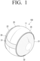
- a shape of the robot 100 formed of the body 11, the left wheel 21, and the right wheel 22 may be a sphere shape. That is, the robot 100 may have an overall spherical shape.
- the transparent regions 31, 32, 33, 34 may be implemented with a material capable of transmitting light having a wavelength of 1550 nm. That is, the transparent regions 31, 32, 33, 34 may be formed of a material capable of transmitting light in a microwave band.
- the LiDAR sensor 110 may be mounted in the body 11 of the robot 100.
- the LiDAR sensor 110 may be installed at a position having a predetermined height with respect to the lower end of the body 11.
- the LiDAR sensor 110 may rotate in 360 degrees and output light.
- the LiDAR sensor 110 may include a light-emitting element/light-receiving element for transmitting and receiving light and a motor for rotating the elements in 360 degrees.
- transparent regions 32 and 33 may be formed in a doughnut shape on each of the left wheel 21 and the right wheel 22.
- the position at which the doughnut shape is formed in the left wheel 21 and the right wheel 22 and the width of the doughnut shape may be determined based on the height at which the LiDAR sensor 110 is installed in the body 11.
- the doughnut-shaped outer side may be adjacent to the contact member 23.
- the width of the doughnut shape may be determined so that the virtual plane may pass through the transparent regions 32, 33. Accordingly, even if the left wheel 21 and the right wheel 22 rotate, the light outputted from the LiDAR sensor 110 may be emitted in the left and right directions of the robot 100 through transparent regions 32, 33 provided in the left wheel 21 and the right wheel 22, respectively.
- a transparent region is provided in a partial region of the body 11 and the left wheel 21 and the right wheel 22, but this is merely an example.
- the entire region of the body 11 may be formed as a transparent region.
- the entire region of the left wheel 21 and the right wheel 22 may be formed as a transparent region.
- the LiDAR sensor 110 irradiates light, and when the irradiated light is reflected and received from an object (for example, an obstacle such as a wall, a home appliance, furniture, a person, a vehicle, etc.) around the robot 100, the LiDAR sensor 110 may detect a distance from the object based on the time when the light is received.
- an object for example, an obstacle such as a wall, a home appliance, furniture, a person, a vehicle, etc.
- the light emitting element may output light.
- the light emitting device may include a circuit for outputting light.
- the light receiving element may receive the reflected light when the output light is reflected by the object.
- the light receiving element may include a circuit for receiving light.
- the LiDAR sensor 110 may rotate in a 360-degree direction and output light.
- the LiDAR sensor 110 may include a light emitting element and a motor for rotating the light receiving element at 360 degrees.
- the sensor 120 may sense posture of the body 11.
- the posture of the body 11 may mean an angle at which the body 11 is tilted.
- the senor 120 may include an inertial measurement unit (IMU) sensor.
- IMU inertial measurement unit
- the sensor 120 may sense a tilted angle of the body 11 by using at least one of a three-axis acceleration sensor and a three-axis gyro sensor.
- the sensor 120 may be mounted on the processor 140 or may be provided in the robot 100 separately from the processor 140.
- the optical device 130 may change the path of light.
- the optical device 130 may include a mirror.
- the mirror may be a micro electro mechanical system (MEMS) mirror.
- MEMS micro electro mechanical system
- the optical device 130 may reflect the received light by using a mirror and output the light by the LiDAR sensor 110.
- the mirror may include a first mirror capable of adjusting an angle and arranged in front of the light emitting element.
- the mirror may include a second mirror capable of adjusting an angle and arranged in front of the light receiving element.
- the processor 140 controls overall operations of the robot 100.
- the processor 140 may be connected to a configuration of the robot 100 including the LiDAR sensor 110, the sensor 120, and the optical device 130, and executes at least one instruction stored in the memory to control the overall operation of the robot 100.
- the processor 140 may be implemented with a plurality of processors as well as a single processor.
- the term processor 140 may be a central processing unit (CPU), an application processor (AP), and the like.
- the processor 140 may obtain information on the posture of the body 11 through the sensor 120.
- the posture of the body 11 may denote an angle at which the body 11 is tilted.
- the processor 140 may obtain information on the tilting angle based on the obtained posture of the body 11 and a refractive index of the transparent regions 31, 32, 33, 34.
- the processor 140 may control the mirror based on the obtained information on the tilting angle.
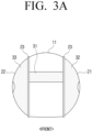
- the LiDAR sensor 110 installed inside the body 11 may also be tilted, and accordingly, the light output from the LiDAR sensor 110 may be output in a direction in which the body 11 is tilted.
- the processor 140 may obtain information on the tilting angle of the mirror corresponding to the posture of the body 11, and may adjust the angle of the mirror, thus the mirror is tilted according to the obtained tilting angle. Accordingly, when the body 11 is tilted, the light reflected by the mirror may be output in a direction parallel to the ground.
- the LiDAR sensor 110 may be mounted inside the robot 100, and the light output from the LiDAR sensor 110 may pass through the transparent regions 31, 32, 33, 34 and may be output to the outside of the robot 100.
- the processor 140 may adjust the angle of the mirror in consideration of the posture of the body 11 of the robot 100 and the refractive index of the transparent regions 31, 32, 33, 34, thus enabling the light passing through the transparent regions 31, 32, 33, 34 to move in a horizontal direction.
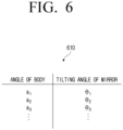
- the robot 100 may further include a memory configured to store information on a plurality of tilting angles corresponding to a plurality of postures of the body 11 obtained based on the refractive index of the transparent regions 31, 32, 33, 34.
- the plurality of tilting angles may be angles to enable lights reflected by the mirror from each of the plurality of postures of the body to be refracted by the transparent region and output in a direction parallel with the ground.
- the light output to the outside of the robot 100 through the transparent region may travel in a horizontal direction.
- a plurality of tilting angles may be experimentally measured and stored in the memory of the robot 100. Specifically, according to an embodiment of the disclosure, it may be measured at which incident angle light should be incident on a transparent region, so that light may be output in a direction parallel to the ground when the light is refracted in a transparent region and then output to outside the transparent region. In addition, for an angle at which the body 11 is tilted, it is possible to measure which degree the mirror should be tilted in order to allow the light outputted from the LiDAR sensor 110 to be incident on the transparent region at the measured incidence angle. According to the method, the tilting angle of the mirror may be measured for the angle at which the body 11 is tilted, and the information on the measured tilting angle may be stored in the memory.
- information 610 on a tilting angle of a mirror corresponding to each angle of the body 11 may be stored in a table form.
- the angle of the body 11 sensed by the sensor 120 is a 1 .
- the processor 140 may obtain a tilting angle ( ⁇ 1 ) matched with the angle a1 of the body 11 among a plurality of tilting angles ( ⁇ 1 , ⁇ 2 , ⁇ 3 ,).
- the processor 140 may adjust the angle of the mirror such that the mirror is tilted according to the obtained tilting angle.
- the processor 140 may output light through the LiDAR sensor 110. Accordingly, the light output from the LiDAR sensor 110 may be reflected by the mirror and output to the outside of the robot 100 through the transparent region.
- the processor 140 may adjust the angles of the first mirror and the second mirror such that the first mirror and the second mirror are tilted at the obtained tilting angle. Accordingly, the light output from the light emitting element may be reflected by the first mirror and then refracted by the transparent region to be output to the outside of the robot 100. In this case, the outputted light may move horizontally from the ground. In addition, when the light output to the outside of the robot 100 is reflected by an object around the robot 100, the reflected light may enter the robot 100 through the transparent region. At this time, the light may be reflected by the second mirror and provided to the LiDAR sensor 110.
- the body 11 of the robot 100 may be tilted counterclockwise.
- the processor 140 may obtain a tilting angle (for example, ⁇ 2 ) of the mirror corresponding to the tilted angle of the body 11, and control the first mirror 131 and the second mirror 132 such that the first mirror 131 and the second mirror 132 are tilted by the tilting angle ( ⁇ 2 ).
- the light output from the light emitting element 111 may be reflected by the first mirror 131 tilted by a tilting angle ( ⁇ 2 ), and the reflected light may be refracted by the transparent region and outputted to the outside of the robot 100. At this time, the light outputted to the outside of the robot 100 may proceed horizontally (see FIG. 7A -1).
- light outputted to the outside of the robot 100 through the transparent region may be reflected by an object around the robot 100 and received in the robot 100.
- the reflected light may be refracted by the transparent region, and the refracted light may be reflected by the second mirror 132 tilted by a tilting angle ( ⁇ 2 ) and received by the light receiving element 112 (see FIG. 7A -2).
- the body 11 of the robot 100 is tilted in a clockwise direction.
- the processor 140 may obtain a tilting angle (for example, ⁇ 3 ) of the mirror corresponding to the tilted angle of the body 11, and control the first mirror 131 and the second mirror 132 such that the first mirror 131 and the second mirror 132 are tilted by the tilting angle ( ⁇ 3 ).
- the light output from the light emitting element 111 is reflected by the first mirror 131 tilted by a tilting angle ( ⁇ 3 ), and the reflected light is refracted by the transparent region and outputted to the outside of the robot 100.
- the light outputted to the outside of the robot 100 may proceed horizontally (see FIG. 7B -1).
- light outputted to the outside of the robot 100 through the transparent region may be reflected by an object around the robot 100 and received in the robot 100.
- the reflected light may be refracted by the transparent region, and the refracted light may be reflected by the second mirror 132 tilted by a tilting angle ( ⁇ 3 ) and received by the light receiving element 112 (see FIG. 7B -2).
- the light output from the LiDAR sensor 110 installed inside the robot 100 may move parallel to the ground from the outside of the robot 100. Accordingly, when the body 11 of the robot 100 having the LiDAR sensor 110 mounted is tilted, the surrounding obstacle may be accurately detected.
- the processor 140 may identify a distance from the object around the robot 100 through the LiDAR sensor 110.
- the processor 140 may detect the distance between the robot 100 and the object based on the time at which the light is received.
- the processor 140 may perform various operations by using the sensed distance. For example, the processor 140 may generate a map for a space in which the robot 100 is located or identify a position of the robot 100 on the map by using a sensed distance and a simultaneous localization and mapping (SLAM) algorithm. In addition, the processor 140 may establish a traveling plan in consideration of the position of the robot 100 on the map, and control the robot 100 to travel while avoiding the object on the map.
- SLAM simultaneous localization and mapping
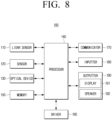
- FIG. 8 is a block diagram illustrating a detailed configuration of an electronic device (such as a robot) according to one or more embodiments of the disclosure.
- the robot 100 may further include a memory 150, a driver 160, a communicator 170, an inputter 180, an outputter 190, and the like, in addition to the LiDAR sensor 110, the sensor 120, the optical device 130, and the processor 140.
- a new configuration may be added or some components may be omitted in addition to such a configuration.
- descriptions overlapping with FIGS. 1 to 7 will be omitted.
- the memory 150 may store at least one instruction and at least one software program for driving the robot 100.
- the memory 150 may include a semiconductor memory such as a flash memory or the like.
- the term memory 130 may include the memory 150, a ROM, a RAM in the processor 140, or a memory card (for example, a micro SD card or a memory stick) mounted on the robot 100.
- the memory 150 may store information on a plurality of tilting angles corresponding to a plurality of postures of the body 11 obtained based on the refractive index of the transparent regions 31, 32, 33, 34.
- the processor 140 may obtain information on the tilting angle of the mirror corresponding to the posture of the body 11 obtained through the sensor 120 by using the information stored in the memory 150.
- the driver 160 is configured to drive the left wheel 21 and the right wheel 22.
- the driver 160 may include a rotary shaft connected to the left wheel 21 and the right wheel 22 and a motor for driving the left wheel 21 and the right wheel 22 by transmitting power to the rotary shaft.
- the processor 140 may drive the wheels 21 and 22 through the driver 160 to perform various driving operations such as movement, stop, speed control, direction change, angular velocity change, or the like, of the robot 100.
- the processor 140 may control the driver 160 to avoid an object by using information on a distance from an object obtained through the LiDAR sensor 110.
- the communicator 170 includes a circuit.
- the communicator 170 may communicate with an external device.
- the processor 140 may receive various data or information from an external device connected through the communicator 170, and may transmit various data or information to an external device.
- the inputter 180 includes a circuit.
- the inputter 180 may receive a user command for setting or selecting various functions supported by the robot 100.
- the inputter 180 may include a plurality of buttons.
- the inputter 180 may be implemented as a touch screen capable of simultaneously performing functions of a display 191.
- the processor 140 may control the operation of the robot 100 based on a user command input through the inputter 180.
- the processor 140 may control the robot 100 based on an on/off command of the robot 100 input through the inputter 180 of the robot 100, an on/off command of a function of the robot 100, and the like.
- the outputter 190 may include the display 191 and a speaker 192.
- the display 191 may display various information.
- the display 191 may be implemented as a liquid crystal display (LCD) liquid or the like.
- the display 191 may be implemented as a touch screen capable of simultaneously performing functions of the inputter 180.
- the processor 140 may display, on the display 191, information related to the operation of the robot 100.
- the speaker 192 may output audio. Specifically, the processor 140 may output various notification sounds or voice guidance messages related to the operation of the robot 100 through the speaker 192.
- the robot 100 may further include a camera.
- the camera may capture the front of the robot 100.
- the processor 140 may recognize an object from an image obtained through the camera to obtain information about a type, a size, a distance to the object, and the like of an object existing around the robot 100.
- the processor 140 may control the driver 160 to avoid the identified object.
- FIG. 9 is a flowchart illustrating a control method according to one or more embodiments of the disclosure.
- the LiDAR sensor may be mounted inside the body of the robot.
- the mirror is controlled based on the obtained information on the tilting angle in operation S930.
- the reflected light is output to outside of the robot through the transparent region in operation S940.
- information on a tilting angle of the mirror comprises obtaining information on a tilting angle corresponding to the obtained posture of the body among the information on a plurality of tilting angles corresponding to the obtained plurality of postures of the body based on the refractive index of the transparent region may be obtained.
- the plurality of tilting angles may be angles to enable lights reflected by the mirror from each of the plurality of postures of the body to be refracted by the transparent region and output in a direction parallel with the ground.
- a 360-degree rotatable left wheel and a right wheel may be provided on left and right sides of a body constituting a central portion of the robot.
- a shape of the robot comprising the body and the wheel may have a spherical shape.
- the LiDAR sensor may output the light while rotating 360 degrees.
- the transparent region may include a first transparent region provided at a position corresponding to a position of the LiDAR sensor on each of a front surface and a rear surface of the body, and a second transparent region provided in a doughnut shape in each of the left wheel and the right wheel.
- the LiDAR sensor includes a light emitting element to output the light; and a light receiving element to, based on the output light being reflected by an object, receive the reflected light.
- the mirror may include a first mirror capable of adjusting an angle and arranged in a front of the light emitting element.
- the mirror may include a second mirror capable of adjusting an angle and arranged in a front of the light receiving element.
- the angles of the first mirror and the second mirror may be adjusted so that the first mirror and the second mirror are tilted at the obtained tilting angle.
- the transparent region may be implemented with a material that passes light output from the LiDAR sensor.
- the methods may be provided as a part of a computer program product.
- the computer program product may be traded between a seller and a buyer.
- the computer program product may be distributed in a form of the machine-readable storage media (e.g., compact disc read only memory (CD-ROM) or distributed online through an application store (e.g., PlayStore TM ).
- an application store e.g., PlayStore TM
- at least a portion of the computer program product e.g., downloadable app
- the storage media such as a manufacturer's server, the application store's server, or a memory in a relay server.
- Each of the components may be composed of one or a plurality of objects, and some subcomponents of the subcomponents described above may be omitted, or other subcomponents may be further included in the embodiments.
- some components e.g., modules or programs
- Operations performed by a module, program, or other component, in accordance with embodiments may be performed sequentially, in a parallel, repetitive, or heuristic manner, or at least some operations may be performed in a different order, omitted, or other operations can be added.
- unit or “module” used in the disclosure includes units includes hardware, software, or firmware, or any combination thereof, and may be used interchangeably with terms such as, for example, logic, logic blocks, parts, or circuits.
- a “unit” or “module” may be an integrally constructed component or a minimum unit or part thereof that performs one or more functions.
- the module may be configured as an application-specific integrated circuit (ASIC).
- ASIC application-specific integrated circuit
- a non-transitory computer readable medium storing a program for sequentially performing a controlling method may be provided.
- the non-transitory computer-readable medium does not refer to a medium that stores data for a short period of time, such as a register, cache, memory, etc., but semi-permanently stores data and is available of reading by the device.
- programs of performing the above-described various methods can be stored in a non-transitory computer readable medium such as a CD, a DVD, a hard disk, a Blu-ray disk, universal serial bus (USB), a memory card, ROM, or the like, and can be provided.
- one or more embodiments of the disclosure may be implemented in software, including instructions stored on machine-readable storage media readable by a machine (e.g., a computer).
- An apparatus may call instructions from the storage medium, and execute the called instruction, including an electronic apparatus (for example, robot 100) according to the embodiments herein.
- the processor may perform a function corresponding to the instructions directly or by using other components under the control of the processor.
- the instructions may include code generated by a compiler or code executable by an interpreter.
Landscapes
- Engineering & Computer Science (AREA)
- Physics & Mathematics (AREA)
- General Physics & Mathematics (AREA)
- Radar, Positioning & Navigation (AREA)
- Remote Sensing (AREA)
- Mechanical Engineering (AREA)
- Robotics (AREA)
- Computer Networks & Wireless Communication (AREA)
- Automation & Control Theory (AREA)
- Electromagnetism (AREA)
- Aviation & Aerospace Engineering (AREA)
- Optics & Photonics (AREA)
- Human Computer Interaction (AREA)
- Control Of Position, Course, Altitude, Or Attitude Of Moving Bodies (AREA)
Applications Claiming Priority (2)
| Application Number | Priority Date | Filing Date | Title |
|---|---|---|---|
| KR1020220094789A KR20240016707A (ko) | 2022-07-29 | 2022-07-29 | 라이다 센서가 탑재된 로봇 및 그의 제어 방법 |
| PCT/KR2023/006102 WO2024025093A1 (fr) | 2022-07-29 | 2023-05-04 | Robot équipé d'un capteur lidar et son procédé de commande |
Publications (2)
| Publication Number | Publication Date |
|---|---|
| EP4470732A1 true EP4470732A1 (fr) | 2024-12-04 |
| EP4470732A4 EP4470732A4 (fr) | 2025-06-18 |
Family
ID=89665202
Family Applications (1)
| Application Number | Title | Priority Date | Filing Date |
|---|---|---|---|
| EP23846754.2A Pending EP4470732A4 (fr) | 2022-07-29 | 2023-05-04 | Robot équipé d'un capteur lidar et son procédé de commande |
Country Status (2)
| Country | Link |
|---|---|
| US (1) | US20240036213A1 (fr) |
| EP (1) | EP4470732A4 (fr) |
Families Citing this family (2)
| Publication number | Priority date | Publication date | Assignee | Title |
|---|---|---|---|---|
| USD1047307S1 (en) * | 2021-11-10 | 2024-10-15 | Samsung Electronics Co., Ltd. | Modular robot for pets |
| USD1114038S1 (en) * | 2023-12-20 | 2026-02-17 | Samsung Electronics Co., Ltd. | Beam projector |
Family Cites Families (5)
| Publication number | Priority date | Publication date | Assignee | Title |
|---|---|---|---|---|
| JP6732651B2 (ja) * | 2016-12-26 | 2020-07-29 | 京セラ株式会社 | ミラーデバイスおよび光走査装置 |
| DE102019110803B3 (de) * | 2019-04-26 | 2020-07-30 | Sick Ag | Sicherheitslaserscanner zur Erfassung von Objekten in einem Überwachungsbereich |
| JP7446921B2 (ja) * | 2020-05-29 | 2024-03-11 | 株式会社東芝 | 移動体、距離計測方法および距離計測プログラム |
| CN116762020A (zh) * | 2020-11-27 | 2023-09-15 | 深圳市大疆创新科技有限公司 | 光学测距装置及其光学窗口、可移动设备 |
| KR102937912B1 (ko) * | 2021-01-12 | 2026-03-11 | 삼성전자주식회사 | 로봇 및 그 제어 방법 |
-
2023
- 2023-05-04 EP EP23846754.2A patent/EP4470732A4/fr active Pending
- 2023-05-31 US US18/203,860 patent/US20240036213A1/en active Pending
Also Published As
| Publication number | Publication date |
|---|---|
| EP4470732A4 (fr) | 2025-06-18 |
| US20240036213A1 (en) | 2024-02-01 |
Similar Documents
| Publication | Publication Date | Title |
|---|---|---|
| EP4470732A1 (fr) | Robot équipé d'un capteur lidar et son procédé de commande | |
| AU2016216750B2 (en) | Cleaning robot and controlling method thereof | |
| CN109421066B (zh) | 机器人 | |
| KR102527645B1 (ko) | 청소 로봇 및 그 제어 방법 | |
| KR20190047595A (ko) | 색 선별 거울을 이용하는 자율 주행 차량용 3d lidar 시스템 | |
| KR20200084934A (ko) | 차량의 주행을 제어하는 장치 및 차량의 주행을 제어하는 장치가 캘리브레이션을 수행하는 방법 | |
| US20240126290A1 (en) | Travel map creating apparatus, travel map creating method, and recording medium | |
| WO2011108210A1 (fr) | Dispositif de mesure de distance tridimensionnelle et robot mobile | |
| EP4206845A1 (fr) | Dispositif automoteur | |
| KR20240016707A (ko) | 라이다 센서가 탑재된 로봇 및 그의 제어 방법 | |
| US20240180387A1 (en) | Robot and method for controlling robot | |
| KR20210087767A (ko) | 자율 주행 무인 대차 | |
| KR20240020880A (ko) | 마스크 맵을 이용하여 주행을 수행하는 로봇 및 그의 주행 방법 | |
| CN114641703B (zh) | 电子设备及其控制方法 | |
| CN110618677A (zh) | 移动机器人 | |
| US20250199144A1 (en) | Sensor module and electronic device comprising same | |
| US20250178677A1 (en) | Robot for moving center of gravity by using mass unit, and center of gravity moving method therefor | |
| KR20250094257A (ko) | 센서 모듈 및 이를 포함하는 전자 장치 | |
| KR20230154700A (ko) | 사물까지의 거리를 산출하는 로봇 및 방법 | |
| US12422848B2 (en) | Robot and method for generating map thereby | |
| KR20230157214A (ko) | 이동형 로봇 및 그 제어 방법 | |
| KR20230072070A (ko) | 로봇 및 로봇의 위치 식별 방법 | |
| JP7739461B2 (ja) | シミュレーションシステム、シミュレーション方法及びシミュレーションプログラム | |
| KR102862646B1 (ko) | 전자 장치 및 그 제어 방법 | |
| US20230356391A1 (en) | Movable robot and controlling method thereof |
Legal Events
| Date | Code | Title | Description |
|---|---|---|---|
| STAA | Information on the status of an ep patent application or granted ep patent |
Free format text: STATUS: THE INTERNATIONAL PUBLICATION HAS BEEN MADE |
|
| PUAI | Public reference made under article 153(3) epc to a published international application that has entered the european phase |
Free format text: ORIGINAL CODE: 0009012 |
|
| STAA | Information on the status of an ep patent application or granted ep patent |
Free format text: STATUS: REQUEST FOR EXAMINATION WAS MADE |
|
| 17P | Request for examination filed |
Effective date: 20240829 |
|
| AK | Designated contracting states |
Kind code of ref document: A1 Designated state(s): AL AT BE BG CH CY CZ DE DK EE ES FI FR GB GR HR HU IE IS IT LI LT LU LV MC ME MK MT NL NO PL PT RO RS SE SI SK SM TR |
|
| A4 | Supplementary search report drawn up and despatched |
Effective date: 20250519 |
|
| RIC1 | Information provided on ipc code assigned before grant |
Ipc: G05D 111/10 20240101ALI20250513BHEP Ipc: G05D 109/10 20240101ALI20250513BHEP Ipc: G05D 1/49 20240101ALI20250513BHEP Ipc: G05D 1/242 20240101ALI20250513BHEP Ipc: G01S 17/931 20200101ALI20250513BHEP Ipc: G01S 7/497 20060101ALI20250513BHEP Ipc: B25J 9/16 20060101ALI20250513BHEP Ipc: B25J 5/00 20060101ALI20250513BHEP Ipc: B25J 19/02 20060101ALI20250513BHEP Ipc: B25J 13/08 20060101AFI20250513BHEP |
|
| DAV | Request for validation of the european patent (deleted) | ||
| DAX | Request for extension of the european patent (deleted) | ||
| STAA | Information on the status of an ep patent application or granted ep patent |
Free format text: STATUS: EXAMINATION IS IN PROGRESS |
|
| 17Q | First examination report despatched |
Effective date: 20260226 |