EP4470747A1 - Element und schnecke für eine gegenläufige doppelschneckenbearbeitungsvorrichtung - Google Patents
Element und schnecke für eine gegenläufige doppelschneckenbearbeitungsvorrichtung Download PDFInfo
- Publication number
- EP4470747A1 EP4470747A1 EP24178548.4A EP24178548A EP4470747A1 EP 4470747 A1 EP4470747 A1 EP 4470747A1 EP 24178548 A EP24178548 A EP 24178548A EP 4470747 A1 EP4470747 A1 EP 4470747A1
- Authority
- EP
- European Patent Office
- Prior art keywords
- curve
- lobe
- flight
- lobes
- counter
- Prior art date
- Legal status (The legal status is an assumption and is not a legal conclusion. Google has not performed a legal analysis and makes no representation as to the accuracy of the status listed.)
- Pending
Links
Images


Classifications
-
- B—PERFORMING OPERATIONS; TRANSPORTING
- B29—WORKING OF PLASTICS; WORKING OF SUBSTANCES IN A PLASTIC STATE IN GENERAL
- B29C—SHAPING OR JOINING OF PLASTICS; SHAPING OF MATERIAL IN A PLASTIC STATE, NOT OTHERWISE PROVIDED FOR; AFTER-TREATMENT OF THE SHAPED PRODUCTS, e.g. REPAIRING
- B29C48/00—Extrusion moulding, i.e. expressing the moulding material through a die or nozzle which imparts the desired form; Apparatus therefor
- B29C48/25—Component parts, details or accessories; Auxiliary operations
- B29C48/251—Design of extruder parts, e.g. by modelling based on mathematical theories or experiments
- B29C48/2517—Design of extruder parts, e.g. by modelling based on mathematical theories or experiments of intermeshing screws
-
- B—PERFORMING OPERATIONS; TRANSPORTING
- B30—PRESSES
- B30B—PRESSES IN GENERAL
- B30B11/00—Presses specially adapted for forming shaped articles from material in particulate or plastic state, e.g. briquetting presses, tabletting presses
- B30B11/22—Extrusion presses; Dies therefor
- B30B11/24—Extrusion presses; Dies therefor using screws or worms
- B30B11/246—Screw constructions
-
- B—PERFORMING OPERATIONS; TRANSPORTING
- B29—WORKING OF PLASTICS; WORKING OF SUBSTANCES IN A PLASTIC STATE IN GENERAL
- B29B—PREPARATION OR PRETREATMENT OF THE MATERIAL TO BE SHAPED; MAKING GRANULES OR PREFORMS; RECOVERY OF PLASTICS OR OTHER CONSTITUENTS OF WASTE MATERIAL CONTAINING PLASTICS
- B29B7/00—Mixing; Kneading
- B29B7/30—Mixing; Kneading continuous, with mechanical mixing or kneading devices
- B29B7/34—Mixing; Kneading continuous, with mechanical mixing or kneading devices with movable mixing or kneading devices
- B29B7/38—Mixing; Kneading continuous, with mechanical mixing or kneading devices with movable mixing or kneading devices rotary
- B29B7/46—Mixing; Kneading continuous, with mechanical mixing or kneading devices with movable mixing or kneading devices rotary with more than one shaft
- B29B7/48—Mixing; Kneading continuous, with mechanical mixing or kneading devices with movable mixing or kneading devices rotary with more than one shaft with intermeshing devices, e.g. screws
- B29B7/481—Mixing; Kneading continuous, with mechanical mixing or kneading devices with movable mixing or kneading devices rotary with more than one shaft with intermeshing devices, e.g. screws provided with paddles, gears or discs
-
- B—PERFORMING OPERATIONS; TRANSPORTING
- B29—WORKING OF PLASTICS; WORKING OF SUBSTANCES IN A PLASTIC STATE IN GENERAL
- B29C—SHAPING OR JOINING OF PLASTICS; SHAPING OF MATERIAL IN A PLASTIC STATE, NOT OTHERWISE PROVIDED FOR; AFTER-TREATMENT OF THE SHAPED PRODUCTS, e.g. REPAIRING
- B29C48/00—Extrusion moulding, i.e. expressing the moulding material through a die or nozzle which imparts the desired form; Apparatus therefor
- B29C48/25—Component parts, details or accessories; Auxiliary operations
- B29C48/36—Means for plasticising or homogenising the moulding material or forcing it through the nozzle or die
- B29C48/395—Means for plasticising or homogenising the moulding material or forcing it through the nozzle or die using screws surrounded by a cooperating barrel, e.g. single screw extruders
- B29C48/40—Means for plasticising or homogenising the moulding material or forcing it through the nozzle or die using screws surrounded by a cooperating barrel, e.g. single screw extruders using two or more parallel screws or at least two parallel non-intermeshing screws, e.g. twin screw extruders
- B29C48/41—Intermeshing counter-rotating screws
-
- B—PERFORMING OPERATIONS; TRANSPORTING
- B29—WORKING OF PLASTICS; WORKING OF SUBSTANCES IN A PLASTIC STATE IN GENERAL
- B29C—SHAPING OR JOINING OF PLASTICS; SHAPING OF MATERIAL IN A PLASTIC STATE, NOT OTHERWISE PROVIDED FOR; AFTER-TREATMENT OF THE SHAPED PRODUCTS, e.g. REPAIRING
- B29C48/00—Extrusion moulding, i.e. expressing the moulding material through a die or nozzle which imparts the desired form; Apparatus therefor
- B29C48/25—Component parts, details or accessories; Auxiliary operations
- B29C48/36—Means for plasticising or homogenising the moulding material or forcing it through the nozzle or die
- B29C48/50—Details of extruders
- B29C48/505—Screws
- B29C48/507—Screws characterised by the material or their manufacturing process
-
- B—PERFORMING OPERATIONS; TRANSPORTING
- B30—PRESSES
- B30B—PRESSES IN GENERAL
- B30B11/00—Presses specially adapted for forming shaped articles from material in particulate or plastic state, e.g. briquetting presses, tabletting presses
- B30B11/22—Extrusion presses; Dies therefor
- B30B11/24—Extrusion presses; Dies therefor using screws or worms
- B30B11/243—Extrusion presses; Dies therefor using screws or worms using two or more screws working in the same chamber
-
- B—PERFORMING OPERATIONS; TRANSPORTING
- B30—PRESSES
- B30B—PRESSES IN GENERAL
- B30B15/00—Details of, or accessories for, presses; Auxiliary measures in connection with pressing
-
- F—MECHANICAL ENGINEERING; LIGHTING; HEATING; WEAPONS; BLASTING
- F04—POSITIVE - DISPLACEMENT MACHINES FOR LIQUIDS; PUMPS FOR LIQUIDS OR ELASTIC FLUIDS
- F04C—ROTARY-PISTON, OR OSCILLATING-PISTON, POSITIVE-DISPLACEMENT MACHINES FOR LIQUIDS; ROTARY-PISTON, OR OSCILLATING-PISTON, POSITIVE-DISPLACEMENT PUMPS
- F04C2/00—Rotary-piston machines or pumps
- F04C2/08—Rotary-piston machines or pumps of intermeshing-engagement type, i.e. with engagement of co-operating members similar to that of toothed gearing
- F04C2/12—Rotary-piston machines or pumps of intermeshing-engagement type, i.e. with engagement of co-operating members similar to that of toothed gearing of other than internal-axis type
- F04C2/14—Rotary-piston machines or pumps of intermeshing-engagement type, i.e. with engagement of co-operating members similar to that of toothed gearing of other than internal-axis type with toothed rotary pistons
- F04C2/16—Rotary-piston machines or pumps of intermeshing-engagement type, i.e. with engagement of co-operating members similar to that of toothed gearing of other than internal-axis type with toothed rotary pistons with helical teeth, e.g. chevron-shaped, screw type
- F04C2/165—Rotary-piston machines or pumps of intermeshing-engagement type, i.e. with engagement of co-operating members similar to that of toothed gearing of other than internal-axis type with toothed rotary pistons with helical teeth, e.g. chevron-shaped, screw type having more than two rotary pistons with parallel axes
-
- B—PERFORMING OPERATIONS; TRANSPORTING
- B29—WORKING OF PLASTICS; WORKING OF SUBSTANCES IN A PLASTIC STATE IN GENERAL
- B29B—PREPARATION OR PRETREATMENT OF THE MATERIAL TO BE SHAPED; MAKING GRANULES OR PREFORMS; RECOVERY OF PLASTICS OR OTHER CONSTITUENTS OF WASTE MATERIAL CONTAINING PLASTICS
- B29B7/00—Mixing; Kneading
- B29B7/30—Mixing; Kneading continuous, with mechanical mixing or kneading devices
- B29B7/34—Mixing; Kneading continuous, with mechanical mixing or kneading devices with movable mixing or kneading devices
- B29B7/38—Mixing; Kneading continuous, with mechanical mixing or kneading devices with movable mixing or kneading devices rotary
- B29B7/46—Mixing; Kneading continuous, with mechanical mixing or kneading devices with movable mixing or kneading devices rotary with more than one shaft
- B29B7/48—Mixing; Kneading continuous, with mechanical mixing or kneading devices with movable mixing or kneading devices rotary with more than one shaft with intermeshing devices, e.g. screws
- B29B7/488—Parts, e.g. casings, sealings; Accessories, e.g. flow controlling or throttling devices
- B29B7/489—Screws
Definitions
- the present disclosure relates to the field of twin-screw processors. More particularly, the disclosure relates to an element for a counter-rotating twin-screw processor.
- the processing elements are configured to rotate in the opposite directions with respect to each other and are generally, non-self-cleaning.
- the counter-rotating twin screw processors are used in production, compounding, and processing of materials such as plastics, food, paint and pharmaceuticals.
- a primary task carried out by the counter-rotating twin screw processors is mixing of the materials to produce a melt.
- elements for a counter rotating processor with reduced material stagnation and improved wiping capabilities are also a need for elements for a counter rotating processor with reduced material stagnation and improved wiping capabilities.
- an element for a counter-rotating twin screw processor having an axial bore for mounting on a screw shaft of the processor.
- the element comprises at least one continuous self-wiping flight helically formed thereon.
- the element also comprises one or more lobes with a lobe profile that is defined in a radial plane of the element.
- the lobe profile of each lobe is provided by a functionally continuous curve obtained by combining a first curve to a second curve.
- the first curve is represented by a mathematical expression and the second curve is a mirror-image of the first curve about a radial axis passing through a central axis of the element and one of two extreme points of the first curve.
- a counter-rotating screw for a counter-rotating twin screw processor defines an axial bore for housing the counter-rotating screw. At least a portion of the counter-rotating screw comprises at least one continuous self-wiping flight helically formed thereon.
- the counter-rotating screw also comprises one or more lobes with a lobe profile that is defined in a radial plane of the counter-rotating screw. The lobe profile of each lobe is provided by a functionally continuous curve obtained by combining a first curve to a second curve.
- a counter-rotating twin-screw processor comprises a barrel defining a first cylindrical bore and a second cylindrical bore. The first cylindrical bore and the second cylindrical bore intersect to form a chamber. A first shaft rotates within the first bore about an axis and a second shaft rotates within the second bore about an axis. At least one element is coupled to the first shaft and the second shaft respectively.
- the element comprises an axial bore for mounting on the first shaft and the second shaft respectively.
- the element also comprises a continuous self-wiping flight helically formed thereon.
- the element comprises one or more lobes with a lobe profile that is defined in a radial plane of the counter-rotating screw.
- the lobe profile of each lobe is provided by a functionally continuous curve obtained by combining a first curve to a second curve.
- the first curve is represented by a mathematical expression and the second curve is a mirror-image of the first curve about a radial axis passing through a central axis of the element and one of two extreme points of the first curve.
- a pair of elements for a twin-screw processor comprises a first shaft and a second shaft.
- the pair of elements comprise a first element adapted to be coupled to the first shaft and a second element adapted to be coupled to the second shaft.
- the first element and the second element each have a continuous self-wiping flight helically formed thereon.
- the first element and the second element each have one or more lobes with a lobe profile that is defined in a radial plane of the first element and the second element respectively.
- the lobe profile is provided by a functionally continuous curve obtained by combining a first curve to a second curve.
- the first curve is represented by a mathematical expression and the second curve is a mirror-image of the first curve about a radial axis passing through a central axis of the first element or the second element and one of two extreme points of the first curve.
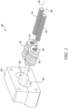
- the processor 100 may comprise a housing 102 having two cylindrical housing bores 104, 106.
- the two cylindrical housing bores 104, 106 may have an axis 108 and 110 respectively disposed parallelly with respect to each other.
- a first screw shaft 112 and a second screw shaft 114 are disposed in the two cylindrical housing bores 104, 106 respectively.
- a pair of processing elements 116, 118 or 'elements' may be mounted on the screw shafts 112, 114 respectively.
- a plurality of such element pairs mounted on respective screw shafts may define various zones within the processor 100 including an intake zone, a mixing zone and an output zone.
- the elements 116, 118 may comprise grooved axial bores 120, 122 in which splines of the screw shafts 112, 114 respectively are engaged. It may be apparent that the elements 116, 118 may also be configured for mounting on the screw shafts 112, 114 via different engagement means.
- the element 116 and the first screw shaft 112 may not be separate components and may define a single component, herein referred to as a "counter-rotating screw”.
- the element 118 and the second screw shaft 114 may not be separate components and define another counter-rotating screw.
- the two counter-rotating screws may be housed in the two cylindrical housing bores 104, 106 respectively. In such embodiments, the two counter-rotating screws may exhibit an outer profile similar to outer profiles of the elements 116, 118 respectively.
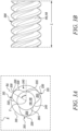
- the elements 116, 118 may each be tri-lobed defined by lobes 205 and 210 respectively.
- the lobes 205 and 210 define screw profiles 215 and 220 of the elements 116, 118 respectively.
- the screw profile 215 on the element 116 determines the screw profile 220 on the element 118 or vice versa. Accordingly, the screw profile 215 is referred to as a generating screw profile and the screw profile 220 is referred to as a generated screw profile.
- the elements 116, 118 are self-wiping such that, the element 116 effects a wiping of the element 118 and vice versa, when the elements 116, 118 are counter-rotated simultaneously in opposite directions A, B respectively.
- the elements 116, 118 may be rotated in clockwise and anti-clockwise directions respectively or vice versa.
- a clearance 225 is provided between the elements 116, 118 and the curvatures of the screw profiles 215, 220 are also configured based on a predefined mathematical expression so as to allow the elements 116, 118 to be self-wiping.
- the clearance 225 provided may be predefined and extend between the elements 116, 118 along a longitudinal length of the elements 116, 118 respectively.
- the clearance 225 may range from 150 ⁇ m to 250 ⁇ m. In an embodiment, the clearance 225 may be defined between a crest portion 230 of the screw profile 215 defined by the lobe 205 associated with the element 116 and a trough portion 235 of the screw profile 220 formed between the lobes 210 associated with the element 118. In an embodiment, the elements 116, 118 may together define a pair of elements with the clearance 225 provided therebetween such that for each cross-section of the element 116 on the first screw shaft 112 there exists a conjugate or a substantially conjugate cross-section of the element 118 on the corresponding second screw shaft 114 that is self-wiping. For purposes of clarity and understanding, the element 116 will be described hereafter in detail and it may be understood that the same would also be applicable to the element 118.
- the lobes 205 of the element 116 define a lobe profile 315 respectively. It may be understood that for instances when the counter-rotating screw is used, in place of the element 116 mounted on the first screw shaft 112, the counter-rotating screw may comprise the lobes 205 defining the lobe profile 315.
- the element 116 defines an inner diameter 305 and an outer diameter 310. In an embodiment, the inner diameter 305 may be defined by trough portions 240 formed between the lobes 205 respectively and the outer diameter 310 may be defined by the crest portions 230 of the lobes 205 respectively.
- the inner diameter 305 may correspond to the inner diameter of the lobe profile 315 and the outer diameter 310 may correspond to the outer diameter of the lobe profile 315.
- the lobe profile 315 is defined in a radial plane R of the element 116.
- the element 116 comprises at least one continuous self-wiping flight 300, helically formed thereon.
- the lobe profile 315 of the lobes 205 respectively when transformed axially in a helical manner defines the continuous self-wiping flight 300.
- the flight 300 formed is continuous without any breaks or interruptions.
- a number of flights formed in the element 116 corresponds to a number of lobes provided in the element 116.
- a tri-lobed element such as the element 116
- having three lobes may define three continuous self-wiping flights helically formed thereon.
- the flight 300 may transform one or more times along an longitudinal length L of the element 116.
- the flight transformation may involve a change in the lobes 205 along the longitudinal length L.
- the change in the lobes 205 may correspond to a change in a number of lobes and/or the lobe profiles associated with the lobes formed on the element 116.
- the lobe profile 315 of the lobes 205 respectively may extend along the entire longitudinal length L of the element 116.
- the lobe profile 315 of the lobes 205 respectively may extend along one or more portions along the longitudinal length L of the element 116.
- the flight 300 may define the continuous self-wiping flight along the portion(s) comprising the lobe profile 315 of the lobes 205 and define a continuous non-self-wiping flight at remaining portion(s) along the longitudinal length L of the element 116.
- a number of lobes and/or their respective lobe profiles in the remaining portion(s) along the longitudinal length L of the element 116 may be different from the number of the lobes 205 and/or their respective lobe profiles 315 in the portion(s) comprising the lobe profile 315.
- the lobe profile 315 of the lobes 205 respectively may extend along one or more portions along the longitudinal length L of the counter-rotating screw.
- the flight 300 may have an integer number of lobes, referred to as “integer lobes”, that typically vary between one to four lobes, extending along the longitudinal length L of the element 116. Such elements are referred to as “integer lobe flight” or elements having a integer lobe flight.
- the flight 300 may also have a non-integer number of lobes, referred to as "non-integer lobes", such as a fractional lobe or irrational lobe, extending along the longitudinal length L of the element 116. Such elements are referred to as “non-integer lobe flight” or elements having a non-integer lobe flight.
- the flight 300 may also have different combinations of integer and/or non-integer lobes extending along the longitudinal length L of the element 116. In an embodiment, the flight 300 may start as an integer or non-integer number of lobes.
- the flight 300 may transform from an integer lobe flight to a non-integer lobe flight or vice versa, or from an integer lobe flight to another integer lobe flight or from a non-integer lobe flight to another non-integer lobe flight.
- a non-integer lobe element may be a fractional lobed element. Examples of a fractional lobe element formed from a single lobe element, a bi-lobe element, a tri-lobe element, and/or a four lobe element are described in U.S. Pat. No. 6,783,270 , U.S. Pat. No. 10,207,423 , and U.S. Pat. No. 10,239,233 .
- a non-integer lobe element may be an irrational number lobed element. Irrational number lobed elements are described in U.S. Pat. No. 8,753,003 .
- a fractional lobed element is an element intermediate a first integer element (n) and a second integer element (N) by a predefined fraction, such that N/n is an integer and the fraction determines the degree of transition between the first integer and the second integer.
- a single flight lobe and a bi-lobe can form fractional lobes such as 1.2.xx, where xx can be any number from 1 to 99.
- the numbers 1 to 99 define whether the fractional lobe will look more like a single flight element or a bi-lobed element.
- the numbers 1 and 2 in the notation 1.2.xx represent the lobe element intermediate a single flight element (1) and a bi-lobe element respectively (2).
- a fractional lobe element represented as 1.4.50 represents an element mid-way between a single flight and a four lobe element.
- the lobe profile 315 of each lobe 205 is provided by a functionally continuous curve obtained by combining a first curve 320 to a second curve 325.
- the first curve 320 is represented by a predefined mathematical expression.
- the second curve 325 is a mirror-image of the first curve 320 about a radial axis RA passing through a central axis C of the element 116 and one of two extreme points (330, 335) of the first curve 320.
- the second curve 325 is a mirror-image of the first curve 320 about the radial axis RA passing through a central axis C of the element 116 and the extreme point 330 of the first curve 320 that lies on the outer diameter 310 (Do) of the element 116 or the lobe profile 315.
- the angle ⁇ of the radial section 340 varies from 0 to 2 ⁇ radians.
- the radial section 340 corresponds to a circular sector derived from outer diameter 310 (Do) of the element 116 or the lobe profile 315.
- the radial section 340 is defined by ⁇ radian/N.
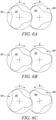
- FIGS. 4-5 and 6A-6C exemplary side-view illustrations of relative rotational movement of the element 118 with respect to the element 116 in the counter-rotating twin screw processor 100 of FIG. 1 is disclosed.
- the element 116 effects a complete wiping of the element 118, when the elements 116, 118 are counter-rotated simultaneously in the opposite directions A, B respectively.
- the clearance 225 provided between the elements 116 and 118 facilitates the self-wiping action when the crest portion 230 of the lobe profile 315 defined by the lobe(s) 205 of the element 116 moves into and/or away from the trough portion 235 of the lobe profile 315 formed between the lobe(s) 210 of the element 118 during the simultaneous counter-rotation in the opposite directions A, B respectively.
- the element 118 also effects a complete wiping of the element 116 when the elements 116, 118 are counter-rotated simultaneously in the opposite directions A, B respectively.
- the clearance 225 provided between the elements 116 and 118 facilitates the self-wiping action as a crest portion 245 of the lobe profile 315 defined by the lobe(s) 210 of the element 118 moves into and/or away from the trough portion 240 of the lobe profile 315 formed between the lobe(s) 205 of the element 116 during the simultaneous counter-rotation in the opposite directions A, B respectively.
- the elements 116, 118 effect a continuous self-wiping action between each other as the the elements 116, 118 are counter-rotated simultaneously in the opposite directions A, B respectively.
- FIGS. 7-9 exemplary side-view illustrations of single lobed, bi-lobed, and four-lobed elements 116, 118 of FIG. 1 are disclosed.
- Lobes 705, 805, 905 associated with the single lobed, bi-lobed, and four-lobed elements 116, 118 are defined by lobe profiles 710, 810, 910 respectively.
- the lobe profile(s) 710, 810, and 910 for each element, for example, the element 116, are provided by functionally continuous curves 715, 815, 915 obtained by combining a first curve 720, 820, 920 to a second curve 725, 825, 925 respectively.
- the first curves 720, 820, 920 are represented by a mathematical expression.
- the second curves 725, 825, 925 are a mirror-image of the first curves 720, 820, 920 respectively about a radial axis RA passing through a central axis C of the element 116 and one of two extreme points (730, 735), (830, 835), (930, 935) of the first curves 720, 820, 920 respectively.
- the elements 116, 118 as taught by the present disclosure are self-wiping and suitable for use in counter-rotating twin screw processors. Consequently, the elements 116, 118 as taught may improve a mixing and/or melting capability of the processor 100 and may help in achieving a homogeneous melt mix. In addition, the elements 116, 118 as taught may also reduce material stagnation and improve an elongational flow of the materials during the melting and homogenizing process. Furthermore, the elements 116, 118 as taught may facilitate the melting and/or homogenizing of the materials at a process temperature lesser than generally involved in the melting and/or homogenizing process in the processor 100. In particular, the elements 116, 118 may be suitable for processing of temperature sensitive materials such as pharmaceutical ingredients including API. The elements 116, 118 may also suitable for processing mixed materials with different melting or softening points such as waste material for recycling.
Landscapes
- Engineering & Computer Science (AREA)
- Mechanical Engineering (AREA)
- Mathematical Physics (AREA)
- Physics & Mathematics (AREA)
- Algebra (AREA)
- General Physics & Mathematics (AREA)
- Mathematical Analysis (AREA)
- Mathematical Optimization (AREA)
- Manufacturing & Machinery (AREA)
- Pure & Applied Mathematics (AREA)
- General Engineering & Computer Science (AREA)
- Processing And Handling Of Plastics And Other Materials For Molding In General (AREA)
- Extrusion Moulding Of Plastics Or The Like (AREA)
Applications Claiming Priority (1)
| Application Number | Priority Date | Filing Date | Title |
|---|---|---|---|
| IN202341036936 | 2023-05-29 |
Publications (1)
| Publication Number | Publication Date |
|---|---|
| EP4470747A1 true EP4470747A1 (de) | 2024-12-04 |
Family
ID=91374910
Family Applications (1)
| Application Number | Title | Priority Date | Filing Date |
|---|---|---|---|
| EP24178548.4A Pending EP4470747A1 (de) | 2023-05-29 | 2024-05-28 | Element und schnecke für eine gegenläufige doppelschneckenbearbeitungsvorrichtung |
Country Status (4)
| Country | Link |
|---|---|
| US (1) | US20240401589A1 (de) |
| EP (1) | EP4470747A1 (de) |
| JP (1) | JP2024171334A (de) |
| CN (1) | CN119036921A (de) |
Cited By (1)
| Publication number | Priority date | Publication date | Assignee | Title |
|---|---|---|---|---|
| EP4556195A1 (de) * | 2023-11-14 | 2025-05-21 | Steer Engineering Private Limited | Element für eine gegendrehende doppelschneckenbearbeitungsvorrichtung |
Families Citing this family (1)
| Publication number | Priority date | Publication date | Assignee | Title |
|---|---|---|---|---|
| WO2022079534A1 (en) * | 2020-10-15 | 2022-04-21 | Steer Engineering Private Limited | An element for a co-rotating twin-screw processor |
Citations (9)
| Publication number | Priority date | Publication date | Assignee | Title |
|---|---|---|---|---|
| US5399012A (en) * | 1991-08-09 | 1995-03-21 | Bayer Aktiengesellschaft | Fully self-cleaning reactor/mixer with a large usable volume |
| US5876115A (en) * | 1996-03-26 | 1999-03-02 | Bayer Aktiengesellschaft | Self-cleaning reactor/mixer for highly viscous and cohesive mixing materials |
| US6260995B1 (en) * | 1998-01-14 | 2001-07-17 | Bayer Aktiengesellschaft | Mixing apparatus |
| US6296461B1 (en) * | 1996-05-16 | 2001-10-02 | City University | Plural screw positive displacement machines |
| US6783270B1 (en) | 2000-07-31 | 2004-08-31 | Steer Engineering (P) Limited | Fractional and higher lobed co-rotating twin-screw elements |
| US8753003B2 (en) | 2009-12-18 | 2014-06-17 | Bayer Intellectual Property Gmbh | Screw feed elements for extrusion of viscoelastic masses |
| US10207423B2 (en) | 2012-02-28 | 2019-02-19 | Steer Engineering Private Limited | Extruder mixing element for a co-rotating twin screw extruder |
| US10239233B2 (en) | 2015-03-23 | 2019-03-26 | Steer Engineering Private Limited | Element for a co-rotating twin screw processor |
| CN112539171A (zh) * | 2020-12-07 | 2021-03-23 | 浙江博大泵业有限公司 | 一种二头三头敷胶双螺杆 |
Family Cites Families (5)
| Publication number | Priority date | Publication date | Assignee | Title |
|---|---|---|---|---|
| JPH10192673A (ja) * | 1997-01-10 | 1998-07-28 | Mitsubishi Heavy Ind Ltd | 攪拌装置 |
| JP5832172B2 (ja) * | 2010-08-05 | 2015-12-16 | 株式会社神戸製鋼所 | 連続混練装置 |
| EP3013551B1 (de) * | 2013-06-24 | 2018-03-21 | Covestro Deutschland AG | Schneckenelemente für mehrwellige schneckenmaschinen und verfahren zu deren herstellung |
| PT3445558T (pt) * | 2016-04-22 | 2022-01-25 | Steerlife India Private Ltd | Processador de lóbulo fracionado e processo relacionado para extrusão de fundido quente |
| WO2022079534A1 (en) * | 2020-10-15 | 2022-04-21 | Steer Engineering Private Limited | An element for a co-rotating twin-screw processor |
-
2024
- 2024-05-28 EP EP24178548.4A patent/EP4470747A1/de active Pending
- 2024-05-28 CN CN202410671847.6A patent/CN119036921A/zh active Pending
- 2024-05-28 US US18/676,287 patent/US20240401589A1/en active Pending
- 2024-05-29 JP JP2024086759A patent/JP2024171334A/ja active Pending
Patent Citations (9)
| Publication number | Priority date | Publication date | Assignee | Title |
|---|---|---|---|---|
| US5399012A (en) * | 1991-08-09 | 1995-03-21 | Bayer Aktiengesellschaft | Fully self-cleaning reactor/mixer with a large usable volume |
| US5876115A (en) * | 1996-03-26 | 1999-03-02 | Bayer Aktiengesellschaft | Self-cleaning reactor/mixer for highly viscous and cohesive mixing materials |
| US6296461B1 (en) * | 1996-05-16 | 2001-10-02 | City University | Plural screw positive displacement machines |
| US6260995B1 (en) * | 1998-01-14 | 2001-07-17 | Bayer Aktiengesellschaft | Mixing apparatus |
| US6783270B1 (en) | 2000-07-31 | 2004-08-31 | Steer Engineering (P) Limited | Fractional and higher lobed co-rotating twin-screw elements |
| US8753003B2 (en) | 2009-12-18 | 2014-06-17 | Bayer Intellectual Property Gmbh | Screw feed elements for extrusion of viscoelastic masses |
| US10207423B2 (en) | 2012-02-28 | 2019-02-19 | Steer Engineering Private Limited | Extruder mixing element for a co-rotating twin screw extruder |
| US10239233B2 (en) | 2015-03-23 | 2019-03-26 | Steer Engineering Private Limited | Element for a co-rotating twin screw processor |
| CN112539171A (zh) * | 2020-12-07 | 2021-03-23 | 浙江博大泵业有限公司 | 一种二头三头敷胶双螺杆 |
Non-Patent Citations (2)
| Title |
|---|
| CHIRUVELLA R V ET AL: "TRANSPORT IN A TWIN-SCREW EXTRUDER FOR THE PROCESSING OF POLYMERS", POLYMER ENGINEERING AND SCIENCE, BROOKFIELD CENTER, US, vol. 36, no. 11, 15 June 1996 (1996-06-15), pages 1531 - 1540, XP000637019, ISSN: 0032-3888, DOI: 10.1002/PEN.10548 * |
| RAUWENDAAL C ED - PIELICHOWSKA KINGA: "THE GEOMETRY OF SELF-CLEANING TWIN-SCREWS EXTRUDERS", ADVANCES IN POLYMER TECHNOLOGY, WILEY AND SONS, HOBOKEN, NJ, US, vol. 15, no. 2, 21 June 1996 (1996-06-21), pages 127 - 133, XP000586048, ISSN: 0730-6679 * |
Cited By (1)
| Publication number | Priority date | Publication date | Assignee | Title |
|---|---|---|---|---|
| EP4556195A1 (de) * | 2023-11-14 | 2025-05-21 | Steer Engineering Private Limited | Element für eine gegendrehende doppelschneckenbearbeitungsvorrichtung |
Also Published As
| Publication number | Publication date |
|---|---|
| JP2024171334A (ja) | 2024-12-11 |
| US20240401589A1 (en) | 2024-12-05 |
| CN119036921A (zh) | 2024-11-29 |
Similar Documents
| Publication | Publication Date | Title |
|---|---|---|
| EP4470747A1 (de) | Element und schnecke für eine gegenläufige doppelschneckenbearbeitungsvorrichtung | |
| US6783270B1 (en) | Fractional and higher lobed co-rotating twin-screw elements | |
| US10029393B2 (en) | Screw elements with improved dispersing action and low energy input | |
| JP5832172B2 (ja) | 連続混練装置 | |
| JP5866333B2 (ja) | 押出機 | |
| EP3219460B1 (de) | Schneckenelement für einen gleichsinnigen rotierenden doppelschneckenprozessor | |
| JP5860973B2 (ja) | 押出機混合要素 | |
| EP2605662B1 (de) | Getriebekasten mit variabel gekoppelter schwingung und rotation für eine knetmaschine | |
| CN103987503A (zh) | 混炼用部件 | |
| US4416544A (en) | Device for mixing, dispersing and homogenizing compounds with at least one viscous component | |
| US5439286A (en) | Methods of constructing drive elements including paddle and shaft assemblies for twin screw mixer and/or processors and the resulting apparatus | |
| US6974243B2 (en) | Screw element for same-sense rotating multi-screw extruders | |
| EP4556195A1 (de) | Element für eine gegendrehende doppelschneckenbearbeitungsvorrichtung | |
| EP1148987B1 (de) | Mehrwellige schneckenextruder-buchse und extruder | |
| EP1005969A1 (de) | Rotor für Elastomermischer mit veränderlichem Gewindegang | |
| US20230390965A1 (en) | An element for a co-rotating twin-screw processor | |
| EP3275612B1 (de) | Mehrwellen-knetmaschine | |
| WO2012161286A1 (ja) | 連続混練機 |
Legal Events
| Date | Code | Title | Description |
|---|---|---|---|
| PUAI | Public reference made under article 153(3) epc to a published international application that has entered the european phase |
Free format text: ORIGINAL CODE: 0009012 |
|
| STAA | Information on the status of an ep patent application or granted ep patent |
Free format text: STATUS: REQUEST FOR EXAMINATION WAS MADE |
|
| 17P | Request for examination filed |
Effective date: 20240528 |
|
| AK | Designated contracting states |
Kind code of ref document: A1 Designated state(s): AL AT BE BG CH CY CZ DE DK EE ES FI FR GB GR HR HU IE IS IT LI LT LU LV MC ME MK MT NL NO PL PT RO RS SE SI SK SM TR |