EP4470807A1 - Module de composants pour un système de pompe à chaleur d'un véhicule - Google Patents
Module de composants pour un système de pompe à chaleur d'un véhicule Download PDFInfo
- Publication number
- EP4470807A1 EP4470807A1 EP24166862.3A EP24166862A EP4470807A1 EP 4470807 A1 EP4470807 A1 EP 4470807A1 EP 24166862 A EP24166862 A EP 24166862A EP 4470807 A1 EP4470807 A1 EP 4470807A1
- Authority
- EP
- European Patent Office
- Prior art keywords
- heat exchanger
- component module
- coolant
- body length
- compressor housing
- Prior art date
- Legal status (The legal status is an assumption and is not a legal conclusion. Google has not performed a legal analysis and makes no representation as to the accuracy of the status listed.)
- Pending
Links
Images

Classifications
-
- F—MECHANICAL ENGINEERING; LIGHTING; HEATING; WEAPONS; BLASTING
- F25—REFRIGERATION OR COOLING; COMBINED HEATING AND REFRIGERATION SYSTEMS; HEAT PUMP SYSTEMS; MANUFACTURE OR STORAGE OF ICE; LIQUEFACTION SOLIDIFICATION OF GASES
- F25B—REFRIGERATION MACHINES, PLANTS OR SYSTEMS; COMBINED HEATING AND REFRIGERATION SYSTEMS; HEAT PUMP SYSTEMS
- F25B30/00—Heat pumps
- F25B30/02—Heat pumps of the compression type
-
- B—PERFORMING OPERATIONS; TRANSPORTING
- B60—VEHICLES IN GENERAL
- B60H—ARRANGEMENTS OF HEATING, COOLING, VENTILATING OR OTHER AIR-TREATING DEVICES SPECIALLY ADAPTED FOR PASSENGER OR GOODS SPACES OF VEHICLES
- B60H1/00—Heating, cooling or ventilating devices
- B60H1/00485—Valves for air-conditioning devices, e.g. thermostatic valves
-
- B—PERFORMING OPERATIONS; TRANSPORTING
- B60—VEHICLES IN GENERAL
- B60H—ARRANGEMENTS OF HEATING, COOLING, VENTILATING OR OTHER AIR-TREATING DEVICES SPECIALLY ADAPTED FOR PASSENGER OR GOODS SPACES OF VEHICLES
- B60H1/00—Heating, cooling or ventilating devices
- B60H1/00271—HVAC devices specially adapted for particular vehicle parts or components and being connected to the vehicle HVAC unit
- B60H1/00278—HVAC devices specially adapted for particular vehicle parts or components and being connected to the vehicle HVAC unit for the battery
-
- B—PERFORMING OPERATIONS; TRANSPORTING
- B60—VEHICLES IN GENERAL
- B60H—ARRANGEMENTS OF HEATING, COOLING, VENTILATING OR OTHER AIR-TREATING DEVICES SPECIALLY ADAPTED FOR PASSENGER OR GOODS SPACES OF VEHICLES
- B60H1/00—Heating, cooling or ventilating devices
- B60H1/00357—Air-conditioning arrangements specially adapted for particular vehicles
- B60H1/00385—Air-conditioning arrangements specially adapted for particular vehicles for vehicles having an electrical drive, e.g. hybrid or fuel cell
- B60H1/00392—Air-conditioning arrangements specially adapted for particular vehicles for vehicles having an electrical drive, e.g. hybrid or fuel cell for electric vehicles having only electric drive means
-
- B—PERFORMING OPERATIONS; TRANSPORTING
- B60—VEHICLES IN GENERAL
- B60H—ARRANGEMENTS OF HEATING, COOLING, VENTILATING OR OTHER AIR-TREATING DEVICES SPECIALLY ADAPTED FOR PASSENGER OR GOODS SPACES OF VEHICLES
- B60H1/00—Heating, cooling or ventilating devices
- B60H1/00507—Details, e.g. mounting arrangements, desaeration devices
- B60H1/00557—Details of ducts or cables
- B60H1/00571—Details of ducts or cables of liquid ducts, e.g. for coolant liquids or refrigerants
-
- B—PERFORMING OPERATIONS; TRANSPORTING
- B60—VEHICLES IN GENERAL
- B60H—ARRANGEMENTS OF HEATING, COOLING, VENTILATING OR OTHER AIR-TREATING DEVICES SPECIALLY ADAPTED FOR PASSENGER OR GOODS SPACES OF VEHICLES
- B60H1/00—Heating, cooling or ventilating devices
- B60H1/32—Cooling devices
- B60H1/3204—Cooling devices using compression
-
- B—PERFORMING OPERATIONS; TRANSPORTING
- B60—VEHICLES IN GENERAL
- B60H—ARRANGEMENTS OF HEATING, COOLING, VENTILATING OR OTHER AIR-TREATING DEVICES SPECIALLY ADAPTED FOR PASSENGER OR GOODS SPACES OF VEHICLES
- B60H1/00—Heating, cooling or ventilating devices
- B60H1/32—Cooling devices
- B60H1/3204—Cooling devices using compression
- B60H1/3223—Cooling devices using compression characterised by the arrangement or type of the compressor
-
- B—PERFORMING OPERATIONS; TRANSPORTING
- B60—VEHICLES IN GENERAL
- B60H—ARRANGEMENTS OF HEATING, COOLING, VENTILATING OR OTHER AIR-TREATING DEVICES SPECIALLY ADAPTED FOR PASSENGER OR GOODS SPACES OF VEHICLES
- B60H1/00—Heating, cooling or ventilating devices
- B60H1/32—Cooling devices
- B60H1/3204—Cooling devices using compression
- B60H1/3227—Cooling devices using compression characterised by the arrangement or the type of heat exchanger, e.g. condenser, evaporator
-
- B—PERFORMING OPERATIONS; TRANSPORTING
- B60—VEHICLES IN GENERAL
- B60H—ARRANGEMENTS OF HEATING, COOLING, VENTILATING OR OTHER AIR-TREATING DEVICES SPECIALLY ADAPTED FOR PASSENGER OR GOODS SPACES OF VEHICLES
- B60H1/00—Heating, cooling or ventilating devices
- B60H1/32—Cooling devices
- B60H1/3204—Cooling devices using compression
- B60H1/3228—Cooling devices using compression characterised by refrigerant circuit configurations
-
- B—PERFORMING OPERATIONS; TRANSPORTING
- B60—VEHICLES IN GENERAL
- B60H—ARRANGEMENTS OF HEATING, COOLING, VENTILATING OR OTHER AIR-TREATING DEVICES SPECIALLY ADAPTED FOR PASSENGER OR GOODS SPACES OF VEHICLES
- B60H1/00—Heating, cooling or ventilating devices
- B60H1/32—Cooling devices
- B60H1/3204—Cooling devices using compression
- B60H1/3229—Cooling devices using compression characterised by constructional features, e.g. housings, mountings, conversion systems
-
- F—MECHANICAL ENGINEERING; LIGHTING; HEATING; WEAPONS; BLASTING
- F25—REFRIGERATION OR COOLING; COMBINED HEATING AND REFRIGERATION SYSTEMS; HEAT PUMP SYSTEMS; MANUFACTURE OR STORAGE OF ICE; LIQUEFACTION SOLIDIFICATION OF GASES
- F25B—REFRIGERATION MACHINES, PLANTS OR SYSTEMS; COMBINED HEATING AND REFRIGERATION SYSTEMS; HEAT PUMP SYSTEMS
- F25B31/00—Compressor arrangements
-
- F—MECHANICAL ENGINEERING; LIGHTING; HEATING; WEAPONS; BLASTING
- F25—REFRIGERATION OR COOLING; COMBINED HEATING AND REFRIGERATION SYSTEMS; HEAT PUMP SYSTEMS; MANUFACTURE OR STORAGE OF ICE; LIQUEFACTION SOLIDIFICATION OF GASES
- F25B—REFRIGERATION MACHINES, PLANTS OR SYSTEMS; COMBINED HEATING AND REFRIGERATION SYSTEMS; HEAT PUMP SYSTEMS
- F25B41/00—Fluid-circulation arrangements
- F25B41/20—Disposition of valves, e.g. of on-off valves or flow control valves
-
- F—MECHANICAL ENGINEERING; LIGHTING; HEATING; WEAPONS; BLASTING
- F25—REFRIGERATION OR COOLING; COMBINED HEATING AND REFRIGERATION SYSTEMS; HEAT PUMP SYSTEMS; MANUFACTURE OR STORAGE OF ICE; LIQUEFACTION SOLIDIFICATION OF GASES
- F25B—REFRIGERATION MACHINES, PLANTS OR SYSTEMS; COMBINED HEATING AND REFRIGERATION SYSTEMS; HEAT PUMP SYSTEMS
- F25B41/00—Fluid-circulation arrangements
- F25B41/30—Expansion means; Dispositions thereof
- F25B41/31—Expansion valves
-
- F—MECHANICAL ENGINEERING; LIGHTING; HEATING; WEAPONS; BLASTING
- F25—REFRIGERATION OR COOLING; COMBINED HEATING AND REFRIGERATION SYSTEMS; HEAT PUMP SYSTEMS; MANUFACTURE OR STORAGE OF ICE; LIQUEFACTION SOLIDIFICATION OF GASES
- F25B—REFRIGERATION MACHINES, PLANTS OR SYSTEMS; COMBINED HEATING AND REFRIGERATION SYSTEMS; HEAT PUMP SYSTEMS
- F25B41/00—Fluid-circulation arrangements
- F25B41/40—Fluid line arrangements
-
- F—MECHANICAL ENGINEERING; LIGHTING; HEATING; WEAPONS; BLASTING
- F25—REFRIGERATION OR COOLING; COMBINED HEATING AND REFRIGERATION SYSTEMS; HEAT PUMP SYSTEMS; MANUFACTURE OR STORAGE OF ICE; LIQUEFACTION SOLIDIFICATION OF GASES
- F25B—REFRIGERATION MACHINES, PLANTS OR SYSTEMS; COMBINED HEATING AND REFRIGERATION SYSTEMS; HEAT PUMP SYSTEMS
- F25B43/00—Arrangements for separating or purifying gases or liquids; Arrangements for vaporising the residuum of liquid refrigerant, e.g. by heat
- F25B43/006—Accumulators
-
- B—PERFORMING OPERATIONS; TRANSPORTING
- B60—VEHICLES IN GENERAL
- B60Y—INDEXING SCHEME RELATING TO ASPECTS CROSS-CUTTING VEHICLE TECHNOLOGY
- B60Y2200/00—Type of vehicle
- B60Y2200/90—Vehicles comprising electric prime movers
- B60Y2200/91—Electric vehicles
-
- B—PERFORMING OPERATIONS; TRANSPORTING
- B60—VEHICLES IN GENERAL
- B60Y—INDEXING SCHEME RELATING TO ASPECTS CROSS-CUTTING VEHICLE TECHNOLOGY
- B60Y2304/00—Optimising design; Manufacturing; Testing
- B60Y2304/01—Minimizing space with more compact designs or arrangements
-
- B—PERFORMING OPERATIONS; TRANSPORTING
- B60—VEHICLES IN GENERAL
- B60Y—INDEXING SCHEME RELATING TO ASPECTS CROSS-CUTTING VEHICLE TECHNOLOGY
- B60Y2304/00—Optimising design; Manufacturing; Testing
- B60Y2304/07—Facilitating assembling or mounting
- B60Y2304/072—Facilitating assembling or mounting by preassembled subunits
Definitions
- the invention relates to a component module for a heat pump system of a vehicle, in particular for a heat pump system of a battery-electric vehicle.
- the component module comprises several components of a heat pump system and is suitable for heating and/or cooling.
- Heat pumps offer an efficient method of transferring heat energy, which is why they are preferred for use in battery electric vehicles (BEVs). Heat pumps are used to control the temperature of the vehicle interior on the one hand and the vehicle batteries on the other. Controlling the temperature of the vehicle batteries ensures optimal operating conditions, which leads to improved performance and extends the service life of the vehicle batteries. This is important to increase the range and reliability of battery electric vehicles. Controlling the temperature involves changing the temperature either for heating or cooling, whereby the heat pump can use various heat sources and heat sinks in different fluid circuits. For example, starting up a BEV at low outside temperatures first requires heating the vehicle batteries, with ambient air serving as the heat source. During electrical charging and discharging, however, cooling the vehicle batteries may be necessary to counteract overheating due to heat generation. The heat generated in the batteries can be released to the environment via coolant circuits or to heat the vehicle interior.
- BEVs battery electric vehicles
- a heat pump system comprises various components that are fluidically connected to one another in a refrigerant circuit. These usually include a compressor for compressing a refrigerant, a first heat exchanger that functions as an evaporator, a second heat exchanger that functions as a condenser and an expansion device to change the pressure of a circulating refrigerant.
- the heat pump system uses the principle of evaporation and condensation of the refrigerant, whereby heat is transferred in the heat exchangers between the refrigerant and another fluid, for example a coolant in a separate coolant circuit. The coolant is then used to transport the heat to the desired location in or on the vehicle.
- the heating and/or cooling module described therein comprises as components a compressor with a heat exchanger for heat transfer between a refrigerant and a coolant as well as a storage device for storing refrigerant.
- the individual components are fluidically connected to one another in such a way that a refrigerant can circulate.
- the arrangement of the components is oriented along a spatial axis system consisting of an L direction, a T direction orthogonal to the L direction and a V direction which is orthogonal to the L and T directions.
- the heat exchanger extends with its longest body size or with its body length parallel to the L direction, whereby the compressor extends with its longest body side, which corresponds to the orientation of the rotation axis of the compressor, essentially along the T direction and thus relative to the Heat exchanger is oriented orthogonally.
- This arrangement enables a space-saving configuration of the components - but requires more installation space in the LV plane spanned by the L and V directions, particularly in the L direction.
- This arrangement of the components means that the connecting lines, such as the refrigerant line between the compressor and the heat exchanger, must extend over the entire LV plane due to the design, which partially blocks access to other cooling or refrigerant lines and to electrical plug connections. Furthermore, the expansion of the arrangement in the LV plane cannot be achieved without additional brackets, since the heat exchanger must be supported relative to the compressor, which is associated with additional costs and increases the weight of the module.
- the invention is based on the object of proposing a component module for a heat pump system of a motor vehicle/BEV, which requires an even smaller installation space volume for the arrangement of the various components and ensures better accessibility to refrigerant and coolant fluid lines as well as electrical connection devices.
- the component module has at least the following components: A compressor for compressing a coolant, wherein the compressor is accommodated in a compressor housing, the body length of which extends along a compressor rotation axis.
- the component arrangement has a first heat exchanger and a second heat exchanger.
- the heat exchangers are designed to transfer heat between a refrigerant and a coolant and have a body length greater than a body width.
- a collecting container for refrigerant is provided in order to store the refrigerant at least partially in liquid form over the course of the refrigerant circuit.
- a fluid distribution device is provided as a further component, which is designed to influence a refrigerant flow path.
- the components have fluid interfaces for refrigerant and/or coolant as well as fluid lines with which the components are fluidically connected to one another.
- fluid lines for refrigerants are referred to as refrigerant fluid lines.
- fluid interfaces for refrigerants or coolants are referred to as refrigerant fluid interfaces or coolant fluid interfaces.
- the components are oriented in their arrangement within the component module as follows:
- the first heat exchanger is oriented with its body length along a first main direction, the second heat exchanger being oriented with its body length orthogonal to the first main direction along a vertical direction.
- the body length of the first heat exchanger thus extends perpendicular to the body length of the second heat exchanger, there being an air gap between the first heat exchanger and the second heat exchanger in order to avoid a thermal bridge.
- the compressor housing is oriented with its body length along a second main direction, which coincides with the compressor rotation axis and is offset in a longitudinal direction parallel to the first main direction.
- the first heat exchanger and the compressor housing are arranged with their body lengths parallel to one another, which reduces an expansion of the component module in the longitudinal direction oriented transversely to the main directions.
- the two parallel main directions, the longitudinal direction and the vertical direction relate to spatial axes, of in which the two main directions and the longitudinal direction oriented perpendicular to the two main directions can lie in one plane, wherein the vertical axis is oriented perpendicularly with respect to the plane formed from the two main directions and the longitudinal direction.
- one of the two main directions and the longitudinal direction form a plane, wherein the other main direction is shifted in the direction of the vertical axis.
- the heat exchangers are essentially designed in the form of a cuboid, which has a body length greater than a body width.
- the cuboid shape can have two different body widths, which are each smaller than the body length.
- the spatial extension of the component module in the first main orientation is achieved by arranging the second heat exchanger with the orientation of its body length in the direction of the vertical axis.
- the first heat exchanger and the second heat exchanger can thus be arranged next to one another along the first main direction without significantly exceeding the spatial extension of the body length of the compressor housing.
- the heat exchangers are dimensioned such that when arranged next to one another along the first main direction, they do not exceed the spatial extension of the body length of the compressor housing.
- the arrangement of the components of the component module according to the invention is based on a uniform expansion in the available spatial directions, with the aim of achieving the smallest possible installation space volume.
- the components are advantageously arranged with their body lengths within the component module in such a way that the spatial expansion of the component module in the relevant spatial directions is minimal.
- a The spatial expansion described in the technique which is significantly larger in a single spatial direction in relation to the expansion in other spatial directions, is avoided, thereby advantageously reducing the required installation space volume.
- a fastening of the first heat exchanger and/or the second heat exchanger to the compressor housing can be provided.
- the first heat exchanger can be fastened to the second heat exchanger, in which case the second heat exchanger is fastened to the compressor housing.
- the first heat exchanger is firmly screwed to the compressor housing.
- the fluid distribution device can have a valve block with at least two, preferably three, particularly preferably four valves, wherein the valves in the valve block are oriented parallel to the vertical direction.
- the valves can be used to create different flow paths for coolant and thus different operating modes for temperature control. While in designs with two valves these serve as expansion valves, designs with three or four valves can implement additional operating modes, such as (inefficient) boost heating operation.
- the valve block of the fluid distribution device and the first heat exchanger can be connected to one another in such a way that the first heat exchanger and the valve block of the fluid distribution device form a fluidic connection for the coolant without external coolant fluid lines being required between the first heat exchanger and the valve block of the fluid distribution device.
- the fluidic connection for coolant is in this case provided by corresponding coolant fluid interfaces formed in the housing of the opposing components.
- the first heat exchanger and the valve block of the fluid distribution device can be in contact with one another on sides facing one another in such a way that between the first heat exchanger and the Valve block no external fluid lines are required.
- seals such as a surface seal, can be arranged between the valve block of the fluid distribution device and the first heat exchanger.
- An air gap can be formed between the compressor housing and the second heat exchanger to avoid a thermal bridge.
- the compressor housing has a high degree of rigidity and a sufficient material volume to form threaded holes into which fastening screws can be screwed to attach the other components.
- the component module is intended in particular for battery electric vehicles (BEVs), since it is designed for heating and/or cooling.
- BEVs battery electric vehicles
- the first heat exchanger and the second heat exchanger are fluidically connected to one another in such a way that the first heat exchanger is designed as an evaporator (chiller) for coolant, with the second heat exchanger being designed as a condenser for coolant.
- the second heat exchanger can be designed as a combination of condenser and internal heat exchanger (IWT) and can thus be used for different operating modes.
- a coolant fluid line can be formed between the second heat exchanger and the valve block of the fluid distribution device.
- An internal heat exchanger refers to the function of a coolant circuit internal heat exchanger.
- Both heat exchangers are suitable for transferring heat between a refrigerant and a coolant.
- the fluidic connection of the heat exchangers enables heating operation and/or cooling operation, so that the component module is suitable for heating and/or cooling.
- the first heat exchanger and the second heat exchanger are thus directly connected to one another in terms of fluid technology.
- the fluid distribution device which is designed to influence the flow paths of the coolant within the component module, can preferably be attached to the compressor housing along the body length of the compressor housing next to the second heat exchanger in such a way that it does not protrude beyond the body length of the second heat exchanger in the vertical direction.
- the installation space height of the fluid distribution device is thus advantageously at the same height or below the spatial extent of the body length of the second heat exchanger in the vertical direction when it is attached to the compressor housing.
- an air gap can be formed between the fluid distribution device and the second heat exchanger, which prevents direct contact between these components.
- the fluid distribution device can be screwed to the compressor housing.
- the collection container for coolant is designed to store coolant in liquid form. Its body length, which preferably has a circular cylindrical shape, can be greater than a body width, wherein the collection container is arranged next to the second heat exchanger with its body length oriented parallel to the vertical direction. Preferably, the collection container is arranged along the first main direction next to the second heat exchanger, so that the second heat exchanger is located along the first main direction in an arrangement between the collection container and the first heat exchanger.
- the collection container can be dimensioned such that it surrounds the second heat exchanger in the vertical direction. not towering over.
- a muffler can be provided as an additional component along the coolant circuit of the component module.
- the muffler can have a body length greater than a body width, wherein according to one embodiment of the component module within the arrangement in the component module next to the collecting container, the muffler can be oriented with its body length essentially parallel to the longitudinal direction. In this orientation, the muffler is arranged offset in the direction of the main directions with respect to the collecting container, transverse to the collecting container.
- the muffler's body length is preferably dimensioned such that it does not protrude beyond the other components of the component module arranged next to one another in the longitudinal direction. Due to its relatively small dimensions, the muffler can also be arranged in a space-saving manner at other positions in the component module.
- the component module has fluid interfaces as fluid connections for connection to a coolant circuit and further fluid interfaces as fluid connections for a refrigerant circuit.
- all coolant fluid interfaces are located on one side of the component module. This means that the coolant connections of the first heat exchanger and the second heat exchanger are oriented towards one side of the component module. All coolant fluid interfaces are therefore advantageously accessible from one side of the component module.
- the second heat exchanger in the arrangement in the component module has an inner side and an outer side, wherein at least one coolant fluid interface is formed on the inner side oriented parallel to the first main direction.
- a coolant fluid line connecting the compressor housing and the second heat exchanger can be connected to the at least one coolant fluid interface
- the inside of the second heat exchanger faces an inside of the oppositely arranged first heat exchanger.
- the heat exchangers arranged next to each other along the first main direction thus have oppositely facing insides, between which an air gap is formed.
- the second heat exchanger On its outer side opposite the inner side, the second heat exchanger can also have refrigerant fluid interfaces, wherein the refrigerant fluid interfaces formed on the outside can be oriented parallel to the first main direction.
- the component module according to the invention realizes an even more compact arrangement of components of a heat pump system, so that an even further reduction in installation space is advantageously achieved. Because the components are fastened to one another and to one another, the component module is given sufficient stability and rigidity without the need for additional brackets or node elements. This contributes to a reduction in weight and ultimately to a reduction in costs.
- the Figure 1 shows a schematic perspective view of an embodiment of the component module 1 for a heat pump system of a vehicle.
- the component arrangement 1 comprises a compressor for compressing a coolant as components, wherein the compressor is accommodated in a compressor housing 2, which extends with its body length along a compressor rotation axis R.
- the component arrangement 1 has a first heat exchanger 3 and a second heat exchanger 4 as further components. Both heat exchangers 3 and 4 have a cuboid shape with a body length greater than a body width.
- the cuboid shape can have two different body widths, which are however each smaller than the body length.
- the first heat exchanger 3 is oriented with its body length along a first main direction T1, wherein the second heat exchanger 4 is oriented with its body length orthogonal to the first main direction T1 along a vertical direction V.
- the body length of the first heat exchanger 3 thus extends perpendicular to the body length of the second heat exchanger 4, wherein an air gap is present between the first heat exchanger 3 and the second heat exchanger 4.
- the first heat exchanger 3 is designed to transfer heat between a coolant and a refrigerant and has two coolant fluid interfaces 3.1 and 3.2.
- the coolant fluid interfaces 3.1 and 3.2 serve as fluid connections for integration into a coolant circuit.
- the first heat exchanger 3 has two refrigerant fluid interfaces, of which only one can be seen in the illustration shown. This is identified by the reference symbol 3.3.
- a first fluid interface 3.3 for refrigerant of the first heat exchanger 3 leads via a refrigerant fluid line 8.1 for the fluidic connection to a Refrigerant fluid interface 4.4 of the second heat exchanger 4.
- the refrigerant fluid line 8.1 is designed as an integral component of the first heat exchanger 3, without projecting beyond the dimensions of the first heat exchanger 3 to an outside of the component module 1.
- the refrigerant fluid interface 4.4 is formed on an inside 11 of the second heat exchanger 4 and is oriented parallel to the first main direction T1.
- the fluid interfaces 3.3 and 4.4 are screwed together.
- the second refrigerant fluid interface of the first heat exchanger 3 is located on a side facing the compressor housing 2, on which the first heat exchanger 3 is advantageously screwed to the compressor housing 2 using two screws. In the exemplary embodiment shown, only one of the two screws 10 can be seen due to the perspective view.
- the compressor housing 2 is oriented with its body length along a second main direction T2, which coincides with the compressor rotation axis R and is offset in a longitudinal direction L parallel to the first main direction T1.
- the second refrigerant fluid interface of the first heat exchanger 3 leads directly into the valve block 6.1 using a refrigerant fluid line.
- a refrigerant fluid line 8.2 leads from the compressor housing 2 to a further refrigerant fluid interface 4.3 for refrigerant formed on the inner side 11 of the second heat exchanger 4, wherein the refrigerant fluid line 8.2 is screwed to the refrigerant fluid interface 4.3.
- This further refrigerant fluid interface 4.3 is oriented parallel to the main direction T1, like the refrigerant fluid interface 4.4.
- the refrigerant fluid lines 8.1 and 8.2 are rigid.
- the refrigerant fluid line 8.2 can be designed to be flexible in some areas.
- the second heat exchanger 4 is fixed in the arrangement of the component module 1.
- a Component module holder 14 is provided, to which the second heat exchanger 4 is attached, wherein the component module holder 14 is screwed to the compressor housing 2.
- a further screw connection of the second heat exchanger 4 to the first heat exchanger 3 and/or the compressor housing 2 can be provided.
- refrigerant fluid interfaces 4.5 and 4.6 are formed on an outer side 12 of the second heat exchanger. These further refrigerant fluid interfaces 4.5 and 4.6 are also oriented parallel to the first main direction T1.
- the second heat exchanger 4 has two coolant fluid interfaces 4.1 and 4.2 in order to enable the second heat exchanger 4 to be integrated into a coolant circuit.
- the coolant fluid interfaces 4.1 and 4.2 are oriented towards an outside of the component module 1.
- the coolant fluid interfaces 3.1 and 3.2 of the first heat exchanger 3 and the coolant fluid interfaces 4.1 and 4.2 of the second heat exchanger 4 are accessible from one side of the component module 1.
- the first heat exchanger 3 is designed to function as an evaporator (chiller) for coolant
- the second heat exchanger 4 is designed to function as a condenser for compressed coolant.
- the second heat exchanger 4 can be designed as a combined heat exchanger with the function of a condenser and the function of an internal heat exchanger.
- the component module 1 has a fluid distribution device 6 for influencing the flow paths of the coolant within the component module 1.
- the fluid distribution device 6 is attached to the compressor housing 2 along the body length of the compressor housing 2 next to the second heat exchanger 4. For fastening, 2 threaded holes (concealed) are formed on the circumference of the compressor housing.
- the fluid distribution device 6 comprises a valve block 6.1 (see Figure 2 ) with four valves 6.2.1 to 6.2.4, which are oriented in the valve block 6.1 parallel to the vertical axis V. The orientation of the valves 6.2.1 to 6.2.4 is thus transverse to the body length of the compressor housing 2 and parallel to the vertical direction V.
- the height of the fluid distribution device 6 ends with the body length of the second heat exchanger 4 in the vertical direction V.
- the valves 6.2.1 and 6.2.2 serve as expansion valves.
- the valve block 6.1 has a direct connection to the compressor or the compressor housing 2 on the refrigerant side, so that no additional external refrigerant fluid lines are required.
- a collecting container 5 for coolant also forms a component of the component module 1. Fluidically connected to the second heat exchanger 4, the collecting container 5 is designed to store coolant in liquid form. Its body length, which has a circular cylindrical shape, is greater than its body diameter, with the collecting container 5 arranged next to the second heat exchanger 4 with its body length oriented parallel to the vertical direction V. Since the body length of the collecting container 5 and the body length of the second heat exchanger 4 are oriented parallel, the collecting container 5 is thus oriented transversely to the first main direction T1 and consequently transversely to the body length of the first heat exchanger 3.
- the collecting container 5 is thus arranged along the first main direction T1 transversely thereto next to the second heat exchanger 4, so that the second heat exchanger 4 is located along the first main direction T1 in an arrangement between the collecting container 5 and the first heat exchanger 3.
- the collecting tank 5 is dimensioned such that it does not protrude beyond the second heat exchanger 4 in the vertical direction V.
- a muffler 7 is provided as a further component of the component module 1.
- the muffler 7 is a component of a the refrigerant fluid line 8.3 which is fluidically connected to the valve block 6.1 and has a body length greater than a body width.
- the muffler 7 is oriented next to the collecting tank 5 with its body length essentially parallel to the longitudinal direction L. In this orientation, the muffler 7 is arranged transversely to the collecting tank 5, offset in the direction of the main directions T1 and T2 with respect to the collecting tank 5.
- the body length of the muffler 7 is dimensioned such that it does not protrude beyond the second heat exchanger 4 or the compressor housing 2 in the longitudinal direction L.
- the muffler 7 can also be arranged in a space-saving manner at other positions in the component module 1.
- the muffler 7 has a refrigerant fluid interface 7.1, the opening of which is oriented parallel to the longitudinal direction L.
- a further refrigerant fluid line 8.4 which is fluidically connected to the valve block 6.1 has a refrigerant fluid interface 13 which is offset in relation to the refrigerant fluid interface 7.1 of the muffler 7 in a direction parallel to the vertical direction V, wherein the opening of the refrigerant fluid line 8.4 is oriented parallel to the longitudinal direction L.
- the spatial extent of the component module 1 is limited in the two main directions T1 and T2 on one side by a front side of the compressor housing 2 and on the opposite side by the muffler 7.
- the spatial extent of the component module 1 is limited by a body length of the compressor housing 2 and on the opposite side by the first heat exchanger 3.
- the spatial extent of the component module 1 in the vertical direction V is limited by the second heat exchanger 4.
- the reference numerals 9.1 to 9.4 indicate electrical interfaces of the component module 1.
- the Figure 1 The embodiment shown is intended in particular for battery-electric vehicles.
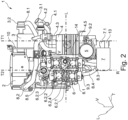
- the Figure 2 shows a top view of the Figure 1 shown embodiment of the component module 1 for a heat pump system of a vehicle in the vertical direction V.
- the top view illustrates the positions of the arrangement of the individual components of the component module 1.
- the arrangement of the second heat exchanger 4 in relation to the compressor housing 2 and the fluid distribution device 6 forms an intermediate space or air gap.
- a further coolant line 8.5 can be seen here, which connects the second heat exchanger 4 to the valve block 6.1.
Landscapes
- Engineering & Computer Science (AREA)
- Thermal Sciences (AREA)
- Mechanical Engineering (AREA)
- Physics & Mathematics (AREA)
- General Engineering & Computer Science (AREA)
- Analytical Chemistry (AREA)
- Chemical & Material Sciences (AREA)
- Power Engineering (AREA)
- Sustainable Energy (AREA)
- Sustainable Development (AREA)
- Life Sciences & Earth Sciences (AREA)
- Air-Conditioning For Vehicles (AREA)
- Compressor (AREA)
Applications Claiming Priority (2)
| Application Number | Priority Date | Filing Date | Title |
|---|---|---|---|
| DE102023114189 | 2023-05-31 | ||
| DE102024100640.4A DE102024100640B4 (de) | 2023-05-31 | 2024-01-10 | Komponentenmodul für ein Wärmepumpensystem eines Fahrzeugs |
Publications (1)
| Publication Number | Publication Date |
|---|---|
| EP4470807A1 true EP4470807A1 (fr) | 2024-12-04 |
Family
ID=90481873
Family Applications (1)
| Application Number | Title | Priority Date | Filing Date |
|---|---|---|---|
| EP24166862.3A Pending EP4470807A1 (fr) | 2023-05-31 | 2024-03-27 | Module de composants pour un système de pompe à chaleur d'un véhicule |
Country Status (4)
| Country | Link |
|---|---|
| US (1) | US12539738B2 (fr) |
| EP (1) | EP4470807A1 (fr) |
| KR (1) | KR20240172038A (fr) |
| CN (1) | CN119058342A (fr) |
Citations (7)
| Publication number | Priority date | Publication date | Assignee | Title |
|---|---|---|---|---|
| US20190039440A1 (en) * | 2017-08-04 | 2019-02-07 | Tesla, Inc. | Technologies for manifolds |
| EP2629040B1 (fr) * | 2012-02-14 | 2020-07-29 | MAHLE International GmbH | Climatiseur à pompe à chaleur unitaire comportant un échangeur de chaleur avec un récepteur monobloc et refroidisseur secondaire |
| WO2021048095A1 (fr) * | 2019-09-09 | 2021-03-18 | Brose Fahrzeugteile SE & Co. Kommanditgesellschaft, Würzburg | Module compact de régulation de la température d'un véhicule motorisé |
| CN215705552U (zh) * | 2021-09-30 | 2022-02-01 | 艾泰斯热系统研发(上海)有限公司 | 一种框架集成式热泵系统及汽车 |
| EP4144549A1 (fr) | 2021-09-03 | 2023-03-08 | Valeo Klimasysteme GmbH | Module de traitement de chauffage et/ou de refroidissement pour véhicule |
| FR3135422A1 (fr) * | 2022-05-10 | 2023-11-17 | Valeo Systemes Thermiques | Système de conditionnement thermique comprenant un module de gestion des fluides pour un véhicule notamment automobile |
| WO2024034900A1 (fr) * | 2022-08-11 | 2024-02-15 | Hanon Systems | Agencement de composants pour composants d'un circuit de fluide frigorigène d'un système de climatisation de véhicule et système de climatisation avec circuit de fluide frigorigène pour un véhicule |
Family Cites Families (5)
| Publication number | Priority date | Publication date | Assignee | Title |
|---|---|---|---|---|
| EP2803686A1 (fr) * | 2013-05-15 | 2014-11-19 | Sika Technology AG | Composition de polyuréthane à deux composants |
| JPWO2021045095A1 (fr) * | 2019-09-06 | 2021-03-11 | ||
| CN113276630B (zh) * | 2021-06-24 | 2022-09-02 | 浙江吉利控股集团有限公司 | 一种热管理集成模块和电动车辆 |
| EP4144548A1 (fr) * | 2021-09-03 | 2023-03-08 | Valeo Klimasysteme GmbH | Module de traitement de chauffage et/ou de refroidissement pour véhicule |
| DE102023118686A1 (de) * | 2022-09-26 | 2024-03-28 | Scania Cv Ab | Verfahren zur Auswahl eines Batteriesystems |
-
2024
- 2024-03-27 EP EP24166862.3A patent/EP4470807A1/fr active Pending
- 2024-04-26 KR KR1020240055859A patent/KR20240172038A/ko active Pending
- 2024-05-08 US US18/657,874 patent/US12539738B2/en active Active
- 2024-05-29 CN CN202410677874.4A patent/CN119058342A/zh active Pending
Patent Citations (7)
| Publication number | Priority date | Publication date | Assignee | Title |
|---|---|---|---|---|
| EP2629040B1 (fr) * | 2012-02-14 | 2020-07-29 | MAHLE International GmbH | Climatiseur à pompe à chaleur unitaire comportant un échangeur de chaleur avec un récepteur monobloc et refroidisseur secondaire |
| US20190039440A1 (en) * | 2017-08-04 | 2019-02-07 | Tesla, Inc. | Technologies for manifolds |
| WO2021048095A1 (fr) * | 2019-09-09 | 2021-03-18 | Brose Fahrzeugteile SE & Co. Kommanditgesellschaft, Würzburg | Module compact de régulation de la température d'un véhicule motorisé |
| EP4144549A1 (fr) | 2021-09-03 | 2023-03-08 | Valeo Klimasysteme GmbH | Module de traitement de chauffage et/ou de refroidissement pour véhicule |
| CN215705552U (zh) * | 2021-09-30 | 2022-02-01 | 艾泰斯热系统研发(上海)有限公司 | 一种框架集成式热泵系统及汽车 |
| FR3135422A1 (fr) * | 2022-05-10 | 2023-11-17 | Valeo Systemes Thermiques | Système de conditionnement thermique comprenant un module de gestion des fluides pour un véhicule notamment automobile |
| WO2024034900A1 (fr) * | 2022-08-11 | 2024-02-15 | Hanon Systems | Agencement de composants pour composants d'un circuit de fluide frigorigène d'un système de climatisation de véhicule et système de climatisation avec circuit de fluide frigorigène pour un véhicule |
Also Published As
| Publication number | Publication date |
|---|---|
| CN119058342A (zh) | 2024-12-03 |
| US12539738B2 (en) | 2026-02-03 |
| KR20240172038A (ko) | 2024-12-09 |
| US20240399835A1 (en) | 2024-12-05 |
Similar Documents
| Publication | Publication Date | Title |
|---|---|---|
| DE102018108013B4 (de) | Vorrichtungen zum Regeln eines Durchflusses und Verteilen eines Fluids in einem Fluidkreislauf | |
| DE10039386B4 (de) | Doppelter Wärmetauscher für Fahrzeugklimaanlage | |
| DE102016200362B4 (de) | Wärmesystem, Elektro- oder Hybridfahrzeug mit einem solchen und Verfahren dafür | |
| DE10128307B4 (de) | Klimaanlage | |
| DE60112279T2 (de) | Fahrzeug- temperaturregulierungssystem mit wärmepumpe | |
| EP3648997B1 (fr) | Installation frigorifique pour véhicule pourvue d'un circuit de réfrigération équipé d'un échangeur thermique et échangeur thermique conçu pour une telle installation frigorifique | |
| EP3595919B1 (fr) | Installation frigorifique d'un véhicule avec un circuit de réfrigérant pouvant fonctionner comme un circuit frigorifique pour un mode ac et comme circuit de pompe à chaleur pour un mode de chauffage | |
| DE102016215851A1 (de) | Kühlvorrichtung für eine Batteriebaugruppe sowie Einheit aus einer Batteriebaugruppe und einer Kühlvorrichtung | |
| DE102016000316A1 (de) | Fahrzeugklimaanlage | |
| DE102019111018A1 (de) | Vorrichtung zum Regeln eines Durchflusses und Verteilen eines Fluids in einem Fluidkreislauf | |
| DE102010055613A1 (de) | Wärmetauscheranordnung zur thermischen Kopplung eines Kühlmittelkreislaufs mit einem Kältemittelkreislauf in einem Fahrzeug | |
| DE102008036755A1 (de) | Schaltschrank | |
| DE102016004999B3 (de) | Fahrzeugklimaanlage | |
| DE102015016241A1 (de) | Elektrisch angetriebenes Fahrzeug | |
| DE102019205575A1 (de) | Vorrichtung zur Kühlung einer Fahrzeugbatterie | |
| EP1266779B1 (fr) | Circuit de refroidissement de véhicule pour le refroidissement d'un dispositif d'augmentation de la température avec un réfrigérant | |
| WO2020058279A1 (fr) | Installation de climatisation sur toit modulaire | |
| EP4355596B1 (fr) | Système de refroidissement pour un véhicule à moteur et procédé de fonctionnement d'un système de refroidissement | |
| DE102024100640B4 (de) | Komponentenmodul für ein Wärmepumpensystem eines Fahrzeugs | |
| EP4470807A1 (fr) | Module de composants pour un système de pompe à chaleur d'un véhicule | |
| DE102012109038B4 (de) | Vorrichtung zur Wärmeübertragung in einem Kältemittelkreislauf | |
| DE102019203183A1 (de) | Kompakte Kältemaschine | |
| DE102018006202A1 (de) | Klimatisierungseinrichtung für ein Kraftfahrzeug | |
| WO2023280442A1 (fr) | Système de gestion thermique destiné au véhicule électrique et soupape de combinaison pour un système de gestion thermique | |
| DE102017212479A1 (de) | Kälteanlage eines Fahrzeugs mit einem Kältemittelkreislauf |
Legal Events
| Date | Code | Title | Description |
|---|---|---|---|
| PUAI | Public reference made under article 153(3) epc to a published international application that has entered the european phase |
Free format text: ORIGINAL CODE: 0009012 |
|
| STAA | Information on the status of an ep patent application or granted ep patent |
Free format text: STATUS: THE APPLICATION HAS BEEN PUBLISHED |
|
| AK | Designated contracting states |
Kind code of ref document: A1 Designated state(s): AL AT BE BG CH CY CZ DE DK EE ES FI FR GB GR HR HU IE IS IT LI LT LU LV MC ME MK MT NL NO PL PT RO RS SE SI SK SM TR |
|
| STAA | Information on the status of an ep patent application or granted ep patent |
Free format text: STATUS: REQUEST FOR EXAMINATION WAS MADE |
|
| 17P | Request for examination filed |
Effective date: 20250528 |
|
| STAA | Information on the status of an ep patent application or granted ep patent |
Free format text: STATUS: EXAMINATION IS IN PROGRESS |
|
| 17Q | First examination report despatched |
Effective date: 20260327 |