EP4470813A1 - Procédé de contrôle d'un dispositif de propulsion d'un véhicule hybride et véhicule hybride - Google Patents
Procédé de contrôle d'un dispositif de propulsion d'un véhicule hybride et véhicule hybride Download PDFInfo
- Publication number
- EP4470813A1 EP4470813A1 EP24184240.0A EP24184240A EP4470813A1 EP 4470813 A1 EP4470813 A1 EP 4470813A1 EP 24184240 A EP24184240 A EP 24184240A EP 4470813 A1 EP4470813 A1 EP 4470813A1
- Authority
- EP
- European Patent Office
- Prior art keywords
- combustion engine
- internal combustion
- electric machine
- time
- operating
- Prior art date
- Legal status (The legal status is an assumption and is not a legal conclusion. Google has not performed a legal analysis and makes no representation as to the accuracy of the status listed.)
- Pending
Links
Images


Classifications
-
- B—PERFORMING OPERATIONS; TRANSPORTING
- B60—VEHICLES IN GENERAL
- B60K—ARRANGEMENT OR MOUNTING OF PROPULSION UNITS OR OF TRANSMISSIONS IN VEHICLES; ARRANGEMENT OR MOUNTING OF PLURAL DIVERSE PRIME-MOVERS IN VEHICLES; AUXILIARY DRIVES FOR VEHICLES; INSTRUMENTATION OR DASHBOARDS FOR VEHICLES; ARRANGEMENTS IN CONNECTION WITH COOLING, AIR INTAKE, GAS EXHAUST OR FUEL SUPPLY OF PROPULSION UNITS IN VEHICLES
- B60K6/00—Arrangement or mounting of plural diverse prime-movers for mutual or common propulsion, e.g. hybrid propulsion systems comprising electric motors and internal combustion engines
- B60K6/20—Arrangement or mounting of plural diverse prime-movers for mutual or common propulsion, e.g. hybrid propulsion systems comprising electric motors and internal combustion engines the prime-movers consisting of electric motors and internal combustion engines, e.g. HEVs
- B60K6/42—Arrangement or mounting of plural diverse prime-movers for mutual or common propulsion, e.g. hybrid propulsion systems comprising electric motors and internal combustion engines the prime-movers consisting of electric motors and internal combustion engines, e.g. HEVs characterised by the architecture of the hybrid electric vehicle
- B60K6/44—Series-parallel type
- B60K6/442—Series-parallel switching type
-
- B—PERFORMING OPERATIONS; TRANSPORTING
- B60—VEHICLES IN GENERAL
- B60K—ARRANGEMENT OR MOUNTING OF PROPULSION UNITS OR OF TRANSMISSIONS IN VEHICLES; ARRANGEMENT OR MOUNTING OF PLURAL DIVERSE PRIME-MOVERS IN VEHICLES; AUXILIARY DRIVES FOR VEHICLES; INSTRUMENTATION OR DASHBOARDS FOR VEHICLES; ARRANGEMENTS IN CONNECTION WITH COOLING, AIR INTAKE, GAS EXHAUST OR FUEL SUPPLY OF PROPULSION UNITS IN VEHICLES
- B60K6/00—Arrangement or mounting of plural diverse prime-movers for mutual or common propulsion, e.g. hybrid propulsion systems comprising electric motors and internal combustion engines
- B60K6/20—Arrangement or mounting of plural diverse prime-movers for mutual or common propulsion, e.g. hybrid propulsion systems comprising electric motors and internal combustion engines the prime-movers consisting of electric motors and internal combustion engines, e.g. HEVs
- B60K6/22—Arrangement or mounting of plural diverse prime-movers for mutual or common propulsion, e.g. hybrid propulsion systems comprising electric motors and internal combustion engines the prime-movers consisting of electric motors and internal combustion engines, e.g. HEVs characterised by apparatus, components or means specially adapted for HEVs
- B60K6/38—Arrangement or mounting of plural diverse prime-movers for mutual or common propulsion, e.g. hybrid propulsion systems comprising electric motors and internal combustion engines the prime-movers consisting of electric motors and internal combustion engines, e.g. HEVs characterised by apparatus, components or means specially adapted for HEVs characterised by the driveline clutches
- B60K6/387—Actuated clutches, i.e. clutches engaged or disengaged by electric, hydraulic or mechanical actuating means
-
- B—PERFORMING OPERATIONS; TRANSPORTING
- B60—VEHICLES IN GENERAL
- B60W—CONJOINT CONTROL OF VEHICLE SUB-UNITS OF DIFFERENT TYPE OR DIFFERENT FUNCTION; CONTROL SYSTEMS SPECIALLY ADAPTED FOR HYBRID VEHICLES; ROAD VEHICLE DRIVE CONTROL SYSTEMS FOR PURPOSES NOT RELATED TO THE CONTROL OF A PARTICULAR SUB-UNIT
- B60W10/00—Conjoint control of vehicle sub-units of different type or different function
- B60W10/02—Conjoint control of vehicle sub-units of different type or different function including control of driveline clutches
-
- B—PERFORMING OPERATIONS; TRANSPORTING
- B60—VEHICLES IN GENERAL
- B60W—CONJOINT CONTROL OF VEHICLE SUB-UNITS OF DIFFERENT TYPE OR DIFFERENT FUNCTION; CONTROL SYSTEMS SPECIALLY ADAPTED FOR HYBRID VEHICLES; ROAD VEHICLE DRIVE CONTROL SYSTEMS FOR PURPOSES NOT RELATED TO THE CONTROL OF A PARTICULAR SUB-UNIT
- B60W10/00—Conjoint control of vehicle sub-units of different type or different function
- B60W10/04—Conjoint control of vehicle sub-units of different type or different function including control of propulsion units
- B60W10/06—Conjoint control of vehicle sub-units of different type or different function including control of propulsion units including control of combustion engines
-
- B—PERFORMING OPERATIONS; TRANSPORTING
- B60—VEHICLES IN GENERAL
- B60W—CONJOINT CONTROL OF VEHICLE SUB-UNITS OF DIFFERENT TYPE OR DIFFERENT FUNCTION; CONTROL SYSTEMS SPECIALLY ADAPTED FOR HYBRID VEHICLES; ROAD VEHICLE DRIVE CONTROL SYSTEMS FOR PURPOSES NOT RELATED TO THE CONTROL OF A PARTICULAR SUB-UNIT
- B60W10/00—Conjoint control of vehicle sub-units of different type or different function
- B60W10/04—Conjoint control of vehicle sub-units of different type or different function including control of propulsion units
- B60W10/08—Conjoint control of vehicle sub-units of different type or different function including control of propulsion units including control of electric propulsion units, e.g. motors or generators
-
- B—PERFORMING OPERATIONS; TRANSPORTING
- B60—VEHICLES IN GENERAL
- B60W—CONJOINT CONTROL OF VEHICLE SUB-UNITS OF DIFFERENT TYPE OR DIFFERENT FUNCTION; CONTROL SYSTEMS SPECIALLY ADAPTED FOR HYBRID VEHICLES; ROAD VEHICLE DRIVE CONTROL SYSTEMS FOR PURPOSES NOT RELATED TO THE CONTROL OF A PARTICULAR SUB-UNIT
- B60W20/00—Control systems specially adapted for hybrid vehicles
- B60W20/40—Controlling the engagement or disengagement of prime movers, e.g. for transition between prime movers
-
- B—PERFORMING OPERATIONS; TRANSPORTING
- B60—VEHICLES IN GENERAL
- B60W—CONJOINT CONTROL OF VEHICLE SUB-UNITS OF DIFFERENT TYPE OR DIFFERENT FUNCTION; CONTROL SYSTEMS SPECIALLY ADAPTED FOR HYBRID VEHICLES; ROAD VEHICLE DRIVE CONTROL SYSTEMS FOR PURPOSES NOT RELATED TO THE CONTROL OF A PARTICULAR SUB-UNIT
- B60W20/00—Control systems specially adapted for hybrid vehicles
- B60W20/10—Controlling the power contribution of each of the prime movers to meet required power demand
- B60W20/13—Controlling the power contribution of each of the prime movers to meet required power demand in order to stay within battery power input or output limits; in order to prevent overcharging or battery depletion
-
- B—PERFORMING OPERATIONS; TRANSPORTING
- B60—VEHICLES IN GENERAL
- B60W—CONJOINT CONTROL OF VEHICLE SUB-UNITS OF DIFFERENT TYPE OR DIFFERENT FUNCTION; CONTROL SYSTEMS SPECIALLY ADAPTED FOR HYBRID VEHICLES; ROAD VEHICLE DRIVE CONTROL SYSTEMS FOR PURPOSES NOT RELATED TO THE CONTROL OF A PARTICULAR SUB-UNIT
- B60W2510/00—Input parameters relating to a particular sub-units
- B60W2510/24—Energy storage means
- B60W2510/242—Energy storage means for electrical energy
- B60W2510/244—Charge state
-
- B—PERFORMING OPERATIONS; TRANSPORTING
- B60—VEHICLES IN GENERAL
- B60W—CONJOINT CONTROL OF VEHICLE SUB-UNITS OF DIFFERENT TYPE OR DIFFERENT FUNCTION; CONTROL SYSTEMS SPECIALLY ADAPTED FOR HYBRID VEHICLES; ROAD VEHICLE DRIVE CONTROL SYSTEMS FOR PURPOSES NOT RELATED TO THE CONTROL OF A PARTICULAR SUB-UNIT
- B60W2520/00—Input parameters relating to overall vehicle dynamics
- B60W2520/10—Longitudinal speed
-
- B—PERFORMING OPERATIONS; TRANSPORTING
- B60—VEHICLES IN GENERAL
- B60W—CONJOINT CONTROL OF VEHICLE SUB-UNITS OF DIFFERENT TYPE OR DIFFERENT FUNCTION; CONTROL SYSTEMS SPECIALLY ADAPTED FOR HYBRID VEHICLES; ROAD VEHICLE DRIVE CONTROL SYSTEMS FOR PURPOSES NOT RELATED TO THE CONTROL OF A PARTICULAR SUB-UNIT
- B60W2540/00—Input parameters relating to occupants
- B60W2540/10—Accelerator pedal position
-
- Y—GENERAL TAGGING OF NEW TECHNOLOGICAL DEVELOPMENTS; GENERAL TAGGING OF CROSS-SECTIONAL TECHNOLOGIES SPANNING OVER SEVERAL SECTIONS OF THE IPC; TECHNICAL SUBJECTS COVERED BY FORMER USPC CROSS-REFERENCE ART COLLECTIONS [XRACs] AND DIGESTS
- Y02—TECHNOLOGIES OR APPLICATIONS FOR MITIGATION OR ADAPTATION AGAINST CLIMATE CHANGE
- Y02T—CLIMATE CHANGE MITIGATION TECHNOLOGIES RELATED TO TRANSPORTATION
- Y02T10/00—Road transport of goods or passengers
- Y02T10/60—Other road transportation technologies with climate change mitigation effect
- Y02T10/62—Hybrid vehicles
Definitions
- the present invention relates to a method for controlling and/or operating a drive device of a hybrid vehicle and a hybrid vehicle which is designed to carry out the method for operating the drive device of the hybrid vehicle.
- a drive device of a hybrid vehicle can comprise, for example, an internal combustion engine and a first electric machine and a second electric machine as well as an electric accumulator.
- different drive units can be used to drive a drive wheel.
- the hybrid drive device has an internal combustion engine that can be operatively connected to a first axle of the motor vehicle, a first electric motor that can also be operatively connected to the first axle, and a second electric motor that can be operatively connected to a second axle of the motor vehicle.
- the electrical energy used to operate the second electric motor is generated by the first electric motor driven by the internal combustion engine by increasing its power or is taken exclusively from an energy storage device for electrical energy.
- the European patent EP 1 074 087 B1 discloses a control method and apparatus for the internal combustion engine of a hybrid electric vehicle, wherein an electric motor or motor/generator is arranged between the engine and the continuously variable or automatic transmission, and wherein the hybrid vehicle has a battery and associated controls.
- a control means maintains the power output of the internal combustion engine substantially along an ideal operating line as the speed of the engine changes.
- a second electric motor may further be provided and the torque output of the second electric motor may be varied by means of a system controller.
- German disclosure document DE 10 2012 103 292 A1 discloses a method for operating an electric drive train of a vehicle, wherein at least two electric motors, which are each operatively connected to a drive axle, and a control device is provided, wherein a driver's desired torque for motor or generator operation is determined, and wherein a required total power of the electrical drive train is determined for a given output speed, and wherein the powers of the individual electric motors are determined, and wherein the resulting power losses of the individual electric motors are minimized on the basis of stored power loss maps for the individual electric motors.
- the German disclosure document DE 10 2009 019 485 A1 discloses a drive train with a first electric motor and a planetary gear and vehicles that have this drive train.
- the drive train has a first electric machine, which can be operated in a motor or generator operating state, and a planetary gear with a speed change device, wherein the planetary gear has an input and an output side and wherein the first electric machine in the motor or generator operating state controls the speed change device so that a gear ratio is formed in the planetary gear.
- the gear ratio of the planetary gear is influenced by the first electric machine, which also determines the operating point of the internal combustion engine.
- the internal combustion engine is operated close to its optimal efficiency.
- the second electric machine works as a motor and the first electric machine is idling or is used as an additional drive. Part of the mechanical energy generated by the internal combustion engine is converted into electrical energy by the first electric machine and passed on directly to the second electric machine. Accelerations are supported by the second electric machine. During deceleration, the energy storage device can be charged by recuperating the braking energy.
- the translation of the European patent specification DE 602 23 850 T2 discloses a method of operating a drive system of a hybrid vehicle, the hybrid vehicle comprising an internal combustion engine, a first electric motor/generator, a planetary gear mechanism and a second electric motor/generator.
- a ratio between a first torque generated by the internal combustion engine at the vehicle axles and a second torque generated by the second electric motor at the vehicle axles at each gear position of the transmission is changed from a first ratio when both the internal combustion engine and the second electric motor operate normally, to a second ratio when either the internal combustion engine or the second electric motor is faulty.
- the German disclosure document DE 10 2007 054 368 A1 discloses a control architecture for selecting an optimal mode or gear ratio and drive speed for a hybrid powertrain system including an internal combustion engine, first and second electric motors, and an electromechanical transmission selectively operable to transmit torque therebetween and operable in a plurality of fixed gear and continuously variable modes. For each allowable operating range state, preferred operating conditions and preferred costs are determined and a preferred operating range state is selected based thereon.
- Cost structure information input to a strategic management facility segment and used in an optimization segment preferably includes operating costs generally determined based on factors related to vehicle drivability, fuel economy, emissions, and battery life for the determined torque range. In addition, costs in fuel and electrical energy consumption associated with the specific operating point of the powertrain system for the vehicle are assigned and allocated.
- the optimal operating cost can be determined by calculating a total powertrain system loss, which includes an expression based on the engine power loss driven by fuel economy and exhaust emissions, plus losses in the mechanical system, losses in the electrical system, and heat losses.
- the method can be carried out, for example, by an engine control unit of the hybrid vehicle.
- the method can be implemented in software and/or hardware.
- the method can be implemented as a computer program that is loaded into an engine control unit of the hybrid vehicle.
- the drive device can drive one or more drive wheels of the hybrid vehicle.
- the internal combustion engine can, for example, comprise a diesel engine or a gasoline engine. and a fuel tank, whereby fuel can be supplied to the combustion chambers of the internal combustion engine in a controlled manner.
- the first electric machine and also the second electric machine can be operated both in electromotive mode (in which they transmit a drive torque to a drive train and/or the drive wheel) and in generator mode (in which they are mechanically driven and generate electrical energy).
- the first electric machine can be operated primarily in generator mode and the second electric machine can be operated primarily in electromotive mode.
- the first electric machine can sometimes also be referred to as a generator and the second electric machine can sometimes also be referred to as a traction machine.
- the drive device can have further operating modes in addition to the three defined operating modes.
- the three different operating modes can be executed in different areas of the coordinate system.
- the drive torque acting on the drive wheel can be generated exclusively by means of the second electric machine.
- the first electric machine can be switched off in this case.
- the second electric machine can be powered exclusively by electrical energy from the accumulator.
- the drive torque acting on the drive wheel can be generated exclusively by means of the second electric machine.
- the second electric machine does not need to obtain electrical energy from the accumulator, but can obtain electrical energy exclusively from electrical energy generated by the first electric machine, with the first electric machine operating in generator mode and being mechanically driven by the internal combustion engine.
- the second electric machine in the serial hybrid operation, can also at least partially obtain energy from the accumulator, whereby the operation can be referred to as boost operation (during the serial hybrid operation).
- the traction drive torque may be generated exclusively by the internal combustion engine.
- the first electric machine and/or the second electric machine may also partially contribute to the traction drive torque in parallel hybrid operation, wherein the operation may be referred to as boost operation (during parallel hybrid operation).
- the change from the first operating mode to the second operating mode can take place by controlling the internal combustion engine, the first electric machine and the second electric machine over a number of points in time.
- the change can take place, for example, within a time period of 0.2 seconds to 2 seconds, in particular approximately 0.4 seconds, without the present invention being restricted in this respect.
- the change from the first operating mode to the second operating mode can take place automatically without manual intervention by the driver.
- the change from the first operating mode to the second operating mode can be triggered by a (changing) requested target drive torque (e.g. indicated by an accelerator pedal position) and/or by a (changing) speed of the hybrid vehicle (or drive wheel rotation speed).
- the change from the first operating mode to the second operating mode can also be triggered by system factors.
- a change from purely electric operation to hybrid operation can be triggered when the battery falls below a minimum permissible state of charge.
- the first operating mode for example, B. a first driving speed and a first wheel speed and a first wheel torque (i.e. first driving drive torque) are present.
- a second driving speed, a second wheel speed and a second driving drive torque can be present in the second operating mode, wherein, for example, in the case of constant (speed) travel on the level, the first driving speed (substantially) corresponds to and/or is equal to the second driving speed, wherein the first wheel speed (substantially) corresponds to and/or is equal to the second wheel speed and wherein the first driving drive torque (substantially) corresponds to and/or is equal to the second driving drive torque.
- the driving speed present during the change from the first operating mode to the second operating mode can (substantially) correspond to and/or is equal to the first and second driving speeds
- the wheel speed present during the change from the first operating mode to the second operating mode can (substantially) correspond to and/or is equal to the first and second wheel speeds
- the wheel speed present during the change from the first operating mode to the second operating mode can (substantially) correspond to and/or is equal to the first and second wheel speeds
- the wheel speed present during the change from the first operating mode to the second operating mode The driving torque must (essentially) correspond to and/or be equal to the first and second driving torque. This means that a driver does not need to notice that an operating mode change is taking place, since no change in speed and no acceleration (or no change in acceleration) occurs during the change. This means that driving comfort can be improved and at the same time the drive device can be operated (almost) optimally, e.g. in terms of energy consumption.
- a total of six possible transitions or changes from a first operating mode to a second operating mode are possible.
- the transitions or changes between a first operating mode and a second operating mode are not referred to here as independent operating modes, but are referred to in this application as (operating mode) changes or (operating mode) transitions.
- the changes or transitions can last for a relatively short period of time (i.e., for example, between 0.1 and 1 second).
- each of the three operating modes can typically last for a longer period of time, for example, between 10 seconds and a few minutes or a few hours.
- the operating mode transitions or changes of operating mode can, for example, be implemented in the form of a traction-neutral operating mode transition in overrun.
- the times of an operating mode change from purely electric operation to serial operation are referred to as the first time, second time, third time, fourth time and fifth time.
- Times during an operating mode change from purely electric operation to parallel operation are referred to below as another first time, another second time, another third time, another fourth time, another fifth time and another sixth time.
- Times during an operating rate change from parallel hybrid operation to serial hybrid operation are referred to below as yet another first time, yet another second time and yet another third time.
- the course between the drive torque provided before and after the change (from the first operating mode to the second operating mode) can correspond to a driver's request and/or be defined by a driver's request.
- the driver's request can be defined by the driver, for example, by a position of a drive lever (in particular accelerator pedal) and/or a brake lever (in particular brake pedal).
- the driver's request can be, for example, acceleration or deceleration or a constant speed.
- the first operating mode can, for example, be purely electric operation and the second operating mode can be serial hybrid operation.
- the second electric machine up to a first point in time (up to which the internal combustion engine can be switched off), the second electric machine can be operated in electromotive mode with electrical energy from the accumulator, whereby electrical energy from the accumulator can only be supplied to the second electric machine.
- the first electric machine can be switched off up to the first point in time. From the first point in time and at least up to a second point in time, from which a speed of the internal combustion engine reaches (i.e. corresponds to and/or is equal to) or exceeds (i.e.
- the first electric machine is operated in electromotive mode to generate a torque in order to increase a speed of the internal combustion engine (to start it).
- the first electric machine can be mechanically coupled to the internal combustion engine (in particular to a crankshaft of the internal combustion engine). This can cause the internal combustion engine to start.
- fuel can be supplied to the internal combustion engine. Furthermore, (compressed) air can be supplied to the internal combustion engine.
- the internal combustion engine itself can thus contribute to a further increase in the speed of the unit consisting of the internal combustion engine and the first electric machine.
- the first electric machine can be operated in generator mode to generate electrical energy. The electrical energy can be supplied to the second electric machine.
- the second electric machine can be operated in electromotive mode by a temporally decreasing supply of electrical energy from the accumulator and a temporally increasing supply of energy by means of the internal combustion engine via the first electric machine. Between the third point in time and the fourth point in time, electrical energy can thus be supplied to the second electric machine from both the accumulator and the first electric machine.
- the second electric machine can be operated in electromotive mode with electrical energy that is generated via the first electric machine by means of the internal combustion engine.
- the second electric machine can be operated by electrical energy that is generated exclusively by the first electric machine, wherein the first electric machine is mechanically driven by the internal combustion engine.
- the internal combustion engine can be started first and, after reaching the target speed for serial hybrid operation, increasingly drive the first electric machine, which thus increasingly (i.e. increasing) generates electrical energy, which is fed to the second electric machine.
- the serial hybrid operation can be carried out with or without load point increase. If the serial operation is carried out with load point increase, between the fourth and a fifth point in time the power output of the internal combustion engine can be increased to a target power that is one load point increase power above a target drive power. From the fifth point in time, the battery can be charged with a charging power corresponding to the load point increase power. Charging the battery can be carried out optionally.
- the switching can include keeping the main clutch open (between the internal combustion engine and the drive wheel) until a further fourth point in time.
- the second electric machine can be operated in electric motor mode until a further first point in time, specifically with electrical energy from the accumulator.
- the second electric machine can only be supplied with energy from the accumulator until the further first point in time.
- the first electric machine can be operated in electromotor mode to generate a torque in order to increase a speed of the internal combustion engine.
- the first electric machine can be mechanically coupled to the internal combustion engine (in particular to a crankshaft of the internal combustion engine). This can cause the internal combustion engine to start.
- fuel (and air) can be supplied to the internal combustion engine, in particular in a controlled manner. The amount of fuel (and/or air) supplied can determine a torque that can be generated by the internal combustion engine.
- the internal combustion engine itself can thus contribute to further increasing the speed of the unit consisting of the internal combustion engine and the first electric machine.
- the first electric machine can be operated in generator mode.
- the first electric machine can be operated in generator mode in order to bring the speed of the internal combustion engine to the target speed for parallel operation (in particular to reduce it) if at the further third point in time the speed of the internal combustion engine exceeds the target speed for parallel hybrid operation.
- the method steps between the further third point in time and the further fourth point in time can be omitted if at the third further point in time the speed of the internal combustion engine corresponds to and/or is equal to the target speed for parallel hybrid operation.
- the main clutch can be closed.
- the internal combustion engine can be operated at the target speed for parallel hybrid operation.
- the drive torque can be generated in an increasing manner by the torque generated by the internal combustion engine and in a decreasing manner by the torque generated by the second electric machine. This allows a power blending or torque blending to be carried out between the fourth point in time and the fifth point in time.
- the drive torque can be generated exclusively by means of the internal combustion engine.
- the power of the internal combustion engine can be increased by a load point increase power above a target drive power and the battery can be charged with a charging power corresponding to the load point increase power.
- the battery can optionally be charged in parallel hybrid operation.
- a load point increase can be carried out, for example, if the charge level of the battery is below a minimum threshold. Other criteria can be added or replace a criterion based on the charge level.
- the first operating mode can be parallel hybrid operation and the second operating mode can be serial hybrid operation, wherein the changeover up to a further first point in time with the main clutch closed comprises generating the drive torque by means of the internal combustion engine, while the second electric machine is switched off.
- the second electric machine can not or does not need to be operated in electric motor operation.
- the first electric machine can be operated in generator operation in order to generate a temporally increasing electrical energy, while the first electric machine is mechanically driven by the internal combustion engine.
- the changeover from the parallel hybrid operation to the serial hybrid operation can comprise using the temporally increasing electrical power in order to transmit a temporally increasing torque to the drive wheel by means of the second electric machine.
- the main clutch can be opened.
- the drive torque can also be generated exclusively (or at least substantially exclusively) by means of the second electric machine.
- the speed of the internal combustion engine can be changed in order to achieve a target speed for serial operation. This can be used, for example, to set an optimal operating point for the internal combustion engine, which, for example, minimizes energy consumption.
- the drive device can comprise a main clutch that can be arranged between the internal combustion engine and the drive wheel, wherein the main clutch can be opened in purely electric operation and/or in serial hybrid operation.
- the drive device can further comprise a first clutch that can be arranged between the first electric machine and the internal combustion engine (and the drive wheel), wherein the first clutch can be opened in purely electric operation and/or in parallel hybrid operation.
- the drive device can further comprise a second clutch that can be arranged between the second electric machine and the drive wheel, wherein the second clutch can be opened in parallel hybrid operation.
- the internal combustion engine, the first electric machine and/or the second electric machine can thus be selectively decoupled from the drive wheel or coupled to the drive wheel during the various operating modes and/or during the operating mode transitions.
- the change from purely electric operation to serial hybrid operation is only carried out according to some embodiments of the present invention if both the driving speed is below a driving speed threshold (and/or the drive wheel speed is below a speed threshold) and a target drive power and/or a target drive torque is above an electric operation threshold (e.g. electric operation torque threshold and/or electric operation power threshold).
- the change from purely electric operation to parallel hybrid operation is only carried out according to some embodiments of the present invention if both the driving speed is above a driving speed threshold (and/or the drive wheel speed is above a speed threshold) and a target drive power and/or a target drive torque is above a further electric operation threshold (e.g. further electric operation torque threshold and/or further electric operation power threshold).
- the change from parallel hybrid operation to serial hybrid operation is only carried out if both the driving speed is above a driving speed threshold (and/or the drive wheel speed is above a speed threshold) and a target drive power and/or a target drive torque is above a parallel hybrid operation threshold (e.g. parallel hybrid operation torque threshold and/or parallel hybrid operation power threshold).
- a parallel hybrid operation threshold e.g. parallel hybrid operation torque threshold and/or parallel hybrid operation power threshold.
- the internal combustion engine When operating the drive device in serial hybrid mode, the internal combustion engine can be operated at an operating point based on a combined efficiency, which depends on the efficiency of the internal combustion engine and the efficiency of the first electric machine. This allows both the effectiveness of the internal combustion engine and the effectiveness of the conversion of mechanical energy into electrical energy by means of the first electric machine to be taken into account in order to find an optimal operating point and/or operating point of the internal combustion engine and to operate the internal combustion engine at this optimal operating point.
- the efficiency of the internal combustion engine can, for example, be determined using a (e.g. experimentally determined) specific fuel consumption (e.g. fuel mass consumed divided by energy generated, e.g. measured in units of g/kWh).
- the efficiency of the internal combustion engine can be higher the lower the specific fuel consumption.
- the specific fuel consumption can, for example, be determined as a function of and/or depend on a speed and a torque or a power of the internal combustion engine. Lines of the same specific fuel consumption (so-called iso lines) can, for example, be shown in a coordinate system which plots the speed of the internal combustion engine against the torque and/or the power of the internal combustion engine. Iso curves for different output powers can also be entered in the same coordinate system.
- the internal combustion engine drives the first electric machine, which generates electrical energy in generator mode, the electrical energy generated in this way being fed to the second electric machine to drive the drive wheel.
- the efficiency of the first electric machine takes into account losses in the conversion of the mechanical energy provided by the internal combustion engine into electrical energy, which takes place by means of the first electric machine.
- the operating point of the internal combustion engine obtained based on the combined efficiency of the first electric machine and the internal combustion engine can differ from the operating point that would be determined based purely on the efficiency of the internal combustion engine.
- the operating point obtained based on the combined efficiency for a given Target drive power and/or given target drive torque can be shifted to higher speeds and/or lower torques of the internal combustion engine. This allows the hybrid vehicle or its drive system to be operated more energy-efficiently and, in particular, in a CO2 -optimized manner in serial hybrid operation.
- the operating point can be an extreme point of the combined efficiency for a given target power and/or a given target torque.
- the extreme point can indicate the argument or arguments (e.g. speed and torque) at which the combined efficiency assumes an extreme value (e.g. minimum or maximum). If the efficiency is represented based on the specific fuel consumption, for example, the point of the argument or arguments (e.g. speed and torque) at which the combined efficiency assumes a maximum can be determined. In some embodiments, this provides a simple rule for determining the operating point.
- the efficiencies of the internal combustion engine and the first electric machine can have been determined beforehand experimentally and/or by simulation and they can in particular have been determined over all possible operating ranges.
- the schematically illustrated hybrid vehicle 1 has a drive device 3 and a drive device controller 6, which is designed to carry out a method for controlling the drive device 3 of the hybrid vehicle 1 according to an embodiment of the present invention.
- the drive device 3 comprises an internal combustion engine 5 with several cylinders 7, a first electric machine (also referred to as a generator) 9, a second electric machine (also referred to as a traction machine) 11 and an accumulator 13, which is connected to both the first electric machine 9 and the second electric machine 11 via power supply cables (and power electronics) not illustrated.
- the drive device 3 can be operated in three operating modes to drive the hybrid vehicle 1. Firstly, in a purely electric mode, in which a driving torque (which is applied, for example, to the drive wheels 15) is produced by means of the second electric machine 11, while the internal combustion engine 5 is switched off (i.e., in particular, no fuel is supplied to it from a tank not shown). Secondly, the drive device 3 can be operated in a serial hybrid mode, in which the driving torque is produced by means of the second electric machine 11 and the internal combustion engine 5 drives the first electric machine 9 to generate electrical energy, which in turn is supplied to the second electric machine 11 (either directly or via the accumulator 13). Thirdly, the drive device 3 can be operated in a parallel hybrid mode, in which a driving torque is produced by means of the internal combustion engine 5 and, in particular, the second electric machine 11 and/or the first electric machine 9 are switched off.
- the drive device 3 further comprises a main clutch K0 (17) and a transmission 19, both of which are arranged between the internal combustion engine 5 and a wheel drive train 21.
- the wheel drive train 21 is mechanically connected to the drive wheels 15 via a differential 25 with associated differential gear 23.
- the first electric machine 9 is connected to an output shaft 31 of the internal combustion engine 5 via a first clutch K1 (27) and via a first gear element 29, wherein the output shaft 31 is mechanically connected to an input shaft 32 of the transmission 19.
- An output shaft 33 of the transmission 19 is connected to the main clutch K0 (17).
- the second electric machine 11 is connected to the wheel drive train 21 via a second gear element 35 and a second clutch K2 (37).
- a series-parallel hybrid concept is implemented in the hybrid vehicle 1.
- the hybrid vehicle 1 can be designed as an HEV (hybrid electric vehicle) or as a plug-in HEV (PHEV).
- the first electric machine 9 (also referred to as EM1) is dimensioned, for example, with regard to the power and torque, such that, taking into account the gear ratio 29 from the internal combustion engine 5 to the first electric machine 9, every possible internal combustion engine operating point (also referred to as the working point) can be set in serial operation.
- the second electric machine 11 also referred to as the electric traction motor EM2), for example, is based on the power dimensioning of the internal combustion engine 5 with regard to the power dimensioning, i.e. it can provide a similar maximum power.
- the reduction ratios of the traction motor EM2 and the generator EM1 can be implemented, for example, both as a spur gear stage and via a (locked) planetary gear.
- the parallel power path (shaft 33) can be decoupled from the drive wheel 15 via the main clutch K0.
- the traction motor EM2 and the generator EM1 can each be decoupled (optionally) via the second clutch 37 (also referred to as K2) and the first clutch 27 (also referred to as K1) in order to reduce drag losses.
- All clutches K0, K1 and K2 can be designed, for example, as friction-locking multi-disk clutches and/or positive-locking claw clutches.
- the generator EM1 can work essentially or exclusively as a generator, it can be used to start the internal combustion engine, or it can be used in parallel hybrid operation to boost support the internal combustion engine 5. Purely electric operation (EV operation) and recuperation can be carried out via the traction motor EM2 (i.e. the second electric machine) while the main clutch K0 is open and the second clutch K2 is closed.
- EV operation Electric operation
- recuperation can be carried out via the traction motor EM2 (i.e. the second electric machine) while the main clutch K0 is open and the second clutch K2 is closed.
- Table 1 lists the different operating modes in which the drive device 3 can be operated, together with the respective coupling states of the main clutch K0, the first clutch K1 and the second clutch K2.
- Table 1 operating mode K0 K1 K2 EV operation open any closed recuperation open any closed Serial hybrid operation with and without load point increase open closed closed Parallel hybrid operation without load point increase closed open open Parallel hybrid operation with load point increase via EM1 closed closed open Parallel hybrid operation with load point increase via EM2 closed open closed
- the drive device 3 can thus be operated in a purely electric mode (EV mode), a serial hybrid mode and a parallel hybrid mode. Both the serial hybrid mode and the parallel hybrid mode can be carried out with or without load point increase, as can be seen from Table 1 above.
- EV mode purely electric mode
- serial hybrid mode and the parallel hybrid mode can be carried out with or without load point increase, as can be seen from Table 1 above.
- An efficient electric drive and efficient recuperation can be achieved via the direct connection of the second electric machine 11 (EM2) to the drive wheel 15.
- EM2 second electric machine 11
- the maximum combustion engine power can be used to drive the vehicle even at very low vehicle speeds and/or wheel speeds, since in this case the main clutch K0 is open and therefore the speed of the combustion engine 5 can be optimally adjusted regardless of the driving speed.
- the first electric machine 9 (Generator EM1) a very comfortable and traction-neutral combustion engine start can be achieved.
- the generator operation required for generating electrical power to charge the battery can be carried out either via the second electric machine 11 (drive motor EM2) or the first electric machine 9 (generator EM1).
- the generators can be used in the Fig. 1
- the second electric machine 11 (drive motor EM2) and the first electric machine 9 (generator EM1) are decoupled by opening the second clutch 37 (K2) and opening the first clutch 27 (K1).
- Fig. 2 illustrates a hybrid vehicle 201 according to another embodiment of the present invention, wherein structurally and/or functionally similar or identical components are used in Fig. 1 and 2 are designated with reference symbols which are identical in the last two digits. For simplification, the following description partly uses the reference symbols from both Fig. 1 and 2 , each separated by a comma.
- the illustrated hybrid vehicle 201 can be understood as a "simplified" system topology without the ability to decouple the traction motor EM2 and generator EM1 and without a transmission (stepped or continuously variable), so that only an overdrive ratio from the internal combustion engine 205 to the drive wheel 215 can be present.
- the main clutch K0 In electrical operation, the main clutch K0 is open.
- the driving request is provided by the electric drive motor EM2 with the corresponding extraction of electrical power from the HV battery.
- the hybrid driving operation can be represented in series and in parallel.
- serial hybrid operation the main clutch K0 is open.
- the speed of the internal combustion engine is freely adjustable.
- the mechanical power of the internal combustion engine is converted into electrical power via the generator EM1. This electrical power is used to recharge the HV battery when required and is also used by the EM2 traction motor to meet the driving requirements.
- the main clutch K0 In parallel hybrid operation, the main clutch K0 is closed.
- the speed of the internal combustion engine is coupled to the wheel speed via the overdrive ratio.
- the mechanical power of the internal combustion engine is used, if required, to recharge the HV battery via the generator EM1 and is mechanically transmitted directly to the wheel to meet the driving requirements.
- the generator EM1 can be decoupled to minimize drag losses (with a loss of dynamics that is acceptable for the driver, e.g. GRA and/or ACC operation).
- the first clutch 227 can also be omitted.
- Fig. 3 illustrated for the parallel hybrid operation in a coordinate system with an abscissa 43, which illustrates the speed of the internal combustion engine 5, 205 in the unit 1/min, and with an ordinate 45, which indicates the power in the unit kW and/or the torque in the unit Nm, which is applied to the input shaft 32 of the transmission 19 or an output shaft 233, a power 47 of the internal combustion engine 5, 205, a system power 49, a torque 51 of the internal combustion engine 5, 205 and a system torque 53 of the respective entire drive device 3, 203.
- the system power 49 and the system torque 53 are defined taking into account an electrical boost support by the generator EM1 (and/or the drive motor EM2). Power and torque requirements (i.e.
- target power or target torque above the full load of the combustion engine can thus be represented in parallel hybrid operation up to the defined system power 49 and up to the defined system torque 53 via a combined combustion and electric motor operation with corresponding electrical power extraction from the accumulator (HV battery) 13, 213.
- the method 38 comprises the method step 42, which comprises changing from the first operating mode to a second operating mode of the three operating modes, wherein the drive torque provided during the change from the first operating mode to the second operating mode substantially corresponds to the drive torque provided before and after the change.
- the Fig. 1 illustrated engine control unit 6 and the Fig. 2 illustrated engine control unit 206 are designed to carry out the method 37.
- the engine control unit 6, 206 is sometimes also referred to as drive device control.
- the different operating modes for driving the hybrid vehicle 1, 201 can be visualized in a diagram of available drive power (and/or target drive power) versus vehicle speed (or drive wheel speed), as in Fig. 5
- the speed of the hybrid vehicle is plotted in km/h and the (available) drive power is plotted in kW on the ordinate 57.
- Purely electric operation (EV operation) is carried out in an area 59 and an area 60
- serial hybrid operation is carried out in an area 61
- parallel hybrid operation parallel hybrid operation
- Curve 64 represents the driving resistance when driving at a constant speed on the flat.
- the Fig. 5 The diagram shown can be analogously displayed as available drive torque (instead of drive power) versus vehicle speed or wheel speed.
- the parallel hybrid operation in the area 63 is carried out if the driving speed is above the driving speed threshold 65, a target drive power is below the driving speed-dependent parallel hybrid operation power threshold 69, and a target drive power is above the further electric operation threshold 68.
- the parallel hybrid operation power threshold 69 is defined here as the sum of the maximum output power 71 of the internal combustion engine 5, 205 and the boost support of the first electric machine 9, 209 and/or the boost support of the second electric machine 11, 211.
- a boost is thus carried out in parallel hybrid operation by means of the first electric machine EM1 and/or the second electric machine EM2.
- the serial hybrid operation is carried out in the range 61 if both the driving speed is below the driving speed threshold 65 and the target drive power is above the electric operation power threshold 67. Furthermore, the serial hybrid operation is carried out in the range 61 if both the driving speed is above the driving speed threshold 65 and the target drive power is above a driving speed-dependent parallel hybrid operation power threshold 69.
- the electric operation is limited with regard to the maximum drive power representation by the electric operation threshold 67 and by the further electric operation threshold 68 (here, for example: up to approx. 49 km/h, approx. 15 kW drive power, from approx. 49 km/h approx. 3 kW drive power).
- the parallel hybrid operation is carried out as soon as, taking into account the gear ratio of the internal combustion engine 5, 205 to the drive wheel 15, 215 a minimum speed of the internal combustion engine 5, 205 is exceeded.
- parallel hybrid operation is limited by the maximum load on the internal combustion engine and, taking into account the electrical boost support by the generator EM1 and/or the drive motor EM2, by the system power (here by the parallel hybrid operation power threshold 71 (without boost) or 69 (with boost)).
- Serial hybrid operation is carried out above the electric operation power threshold 67 and above the parallel hybrid operation power threshold 69.
- Serial hybrid operation is limited in terms of the maximum drive power representation by the dimensioning of the second electric machine 11, 211 (drive motor EM2) by line 75.
- the thresholds 67, 68, 69, 71, 65 can be determined in a consumption-optimized or CO2- optimized manner.
- a CO2 -optimized hybrid operating strategy is derived based on a comparison of the conventional, purely combustion engine drive with an intermittent electric-combustion engine drive.
- hybrid operation in addition to recuperation, the additional fuel consumption due to load point increase and the energy used for electric driving and engine start-up processes must be taken into account. Electric driving is then only permitted for an energetically sensible range for which the overall efficiency is greater than in purely combustion engine operation despite the multiple, loss-making energy conversions.
- the transition from electric driving to hybrid driving occurs when the driver's desired drive power derived from the pedal value exceeds a predetermined value.
- This power threshold which also depends on the wheel speed or the vehicle speed, is determined in a fuel-efficient manner using a mathematical optimization process that takes into account all drive train component efficiencies for various driving cycles.
- a maximum drive power of approx. 15 kW for electric operation up to approx. 49 km/h or a maximum drive power of approx. 3 kW for electric operation from 50 km/h can result, without the present invention being limited to these values and limits.
- the three operating modes of the drive device 3, 203 can be carried out in different areas, which are defined, among other things, by the driving speed (and/or drive wheel speed) and drive power (and/or drive torque or drive torque), as described in Fig. 5 is illustrated schematically.
- Fig. 6 illustrated in graphs 77, 79, 81 curves of a power (graph 77) in the unit kW, a torque (graph 79) in the unit Nm and a speed (graph 81) in the unit rpm of components of the drive device 3, 203, each plotted against time on abscissa 83, which are carried out during an operating mode change from a purely electric driving mode to the serial hybrid mode according to an embodiment of the present invention.
- curve 85 illustrates the power of the second electric machine 11 or 211
- curve 87 illustrates the power of the first electric machine 9 or 209
- curve 89 illustrates the (driving) power of the internal combustion engine 5 or 205
- curve 91 illustrates the power at the drive wheel 15 or 215
- curve 93 illustrates the power of the accumulator (and/or HV battery) 13 or 213.
- the power delivered by the respective components is positive and the power absorbed is negative.
- the curve 95 illustrates the torque of the second electric machine 11, 211
- the curve 97 illustrates the torque of the first electric machine 9, 209
- the curve 99 illustrates the driving torque of the internal combustion engine 3, 203
- the curve 101 illustrates the starting torque of the internal combustion engine
- the curve 103 illustrates the torque applied to the drive wheel 15, 215.
- the curve 105 illustrates the speed of the second electric machine 11 or 211
- the curve 107 illustrates the speed of the first electric machine 9, 209
- the curve 109 illustrates the speed of the internal combustion engine 5, 205
- the curve 111 illustrates the speed of the drive wheel 15 or 215.
- curves that are temporarily congruent i.e., lying on top of each other are (partially) plotted with slight distances from each other with respect to the abscissas.
- the purely electric driving mode (electric driving) is present, which is represented by a power extraction from the accumulator (and/or HV battery) 13 or 213.
- the vehicle 1 or 201 is thus driven exclusively by the second electric machine 11 or 211.
- the case shown in graphs 77, 79, 81 is a driving operation with a constant driving speed, i.e. the wheel speed and wheel torque (and consequently also the drive power) are constant.
- the main clutch K0 also with reference numerals 17 or 217 in Fig. 1 and 2
- the unit consisting of the internal combustion engine 5 or 205 and the first electric machine (generator) 9 or 209 is stationary to avoid drag losses during electric driving.
- the speed of the internal combustion engine 5 or 205 and also the speed of the first electric machine 9 or 209 are zero until the first time t1.
- the start sequence begins at time t1 from a start command given by the hybrid coordinator.
- the control of the first electric machine 9 or 209 sets a torque on the first electric machine 9 or 209 and thus increases the speed of the unit consisting of the internal combustion engine 5 or 205 and the first electric machine 9 or 209 until a speed of the internal combustion engine 5 or 205 of approximately 200 rpm is set at a second time t2.
- Other values are possible.
- the speed of the internal combustion engine 5 or 205 is thus brought to a speed that corresponds to and/or is equal to a start speed threshold 113 by the second time t2.
- the internal combustion engine 5 or 205 can also contribute to a further increase in the speed of the unit consisting of the distribution engine 5 or 205 and the first electric machine 9 or 209 via its own fuel injection and the associated presentation of a starting torque.
- the effective internal combustion engine torque on the crankshaft for driving the hybrid vehicle remains zero.
- the torque of the first electric machine 9 or 209 can also be reduced or set to zero between the second time t2 and the third time t3, and thus the increase in speed of the unit consisting of the internal combustion engine 5 or 205 and the first electric machine 9 or 209 can be implemented exclusively via the fuel injection of the internal combustion engine.
- the internal combustion engine 5 or 205 has reached a target speed 115 for serial operation.
- the torque of the first electric machine 9 or 209 and the starting torque of the internal combustion engine or the internal combustion engine 5 or 205 can be reduced to increase the speed of the unit consisting of the internal combustion engine 5 or 205 and the first electric machine 9 or 209.
- a power blending takes place, which transfers the required drive power from the accumulator 13 or 213 (and/or HV battery) to the internal combustion engine 5 or 205.
- the internal combustion engine 5 or 205 builds up effective torque (and as a result, internal combustion engine power).
- the internal combustion engine power is converted into electrical energy via a corresponding torque build-up on the first electric machine 9 or 209, which is transferred directly to the second electric machine (traction machine) 11 or 211 to represent and/or generate the wheel drive power or to represent the required drive power.
- the power taken from the HV battery 13 or 213 to represent the required drive power can be gradually reduced to zero until the required drive power is provided exclusively by the internal combustion engine 5 or 205 at a fourth time t4.
- the change in operating mode from purely electric operation to serial hybrid operation can be completed at a fourth time t4. From the fourth time t4, the operating mode is therefore serial hybrid operation.
- the torque build-up at the internal combustion engine 5 or 205 and the corresponding torque build-up at the first electric machine 9 or 209 is continued from the fourth time t4 to a fifth time t5.
- the associated power build-up at the internal combustion engine 5 or 205 which exceeds the required drive power, is fed via the first electric machine 9 or 209 into the accumulator 13 or 213 to represent a Load point increase (recharging of the accumulator 13 or 213) (serial hybrid drive with load point increase from t5).
- the main clutch K0 also known as the separating clutch, remains open at all times. Furthermore, the drive wheel speed and the drive wheel torque (and consequently also the drive wheel power) remain constant throughout the entire process, so that the change in operating mode from purely electric operation to serial hybrid operation can be carried out without interrupting traction.
- the entire process can last for a period of approximately 0.2 to 0.5 seconds (duration from the first time t1 to the fifth time t5) and/or not exceed 0.5 seconds and can therefore be implemented very quickly.
- Fig. 7 illustrates graphs 117, 119, 121, which illustrate power in the unit kW, torque in the unit Nm and speed in the unit rpm against time (abscissa 83) during an operating mode change from purely electric driving to parallel hybrid operation according to an embodiment of the present invention.
- a curve 123 illustrates the power of the second electric machine 11 or 211
- a curve 125 illustrates the power of the first electric machine 9 or 209
- a curve 127 illustrates the (driving) power of the internal combustion engine 5 or 205
- a curve 129 illustrates the power at the drive wheel 15 or 215
- a curve 131 illustrates the power of the accumulator 13 or 213.
- a curve 133 illustrates the torque of the second electric machine 11 or 211
- a curve 135 illustrates the torque of the first electric machine 9 or 209
- a curve 137 illustrates a driving torque of the internal combustion engine 5 or 205
- a curve 139 illustrates a starting torque of the internal combustion engine 5 205
- a curve 141 illustrates a drive torque of the drive wheel 15 or 215.
- a curve 143 illustrates the rotational speed of the second electric machine 11 or 211
- a curve 145 illustrates a rotational speed of the first electric machine 9 or 209
- a curve 147 illustrates a rotational speed of the internal combustion engine 9 or 209
- a curve 149 illustrates a rotational speed of the drive wheel 15 or 215.
- curves that are temporarily congruent i.e., lying on top of each other are (partially) plotted with slight distances from each other with respect to the abscissas.
- purely electric operation (electric driving) takes place, which is represented by power being drawn from the accumulator 13 or 213.
- this is driving at a constant driving speed, i.e. the drive wheel speed and drive wheel torque (and consequently also the drive wheel power) are constant.
- the main clutch K0 also referred to as the separating clutch, is open up to a further fourth point in time t4', and closed from the further fourth point in time t4'.
- the unit comprising the internal combustion engine and the first electric machine 9 or 209 is stationary during purely electric operation to avoid drag losses. The speed of the internal combustion engine 5 or 205 and the speed of the first electric machine 9 or 209 are therefore zero.
- the start sequence begins at a further time t1' with a start command given by the hybrid coordinator.
- the control of the first electric machine 9 or 209 sets a torque on the first electric machine 9 or 209 and thus increases the speeds of the unit consisting of the internal combustion engine 5 or 205 and the first electric machine 9 or 209 until the speed of the internal combustion engine 5, 205 reaches a start speed threshold 113 at a further second time t2'.
- the start speed threshold 113 can be, for example, approximately 200 rpm. Other values are possible.
- the internal combustion engine 5, 205 itself can contribute to a further increase in the speed of the unit consisting of the internal combustion engine 5 or 205 and the first electric machine 9 or 209 via its own fuel injection and the associated representation of a start torque.
- the effective combustion engine torque on the crankshaft to drive the hybrid vehicle remains zero.
- the internal combustion engine 5 or 205 reaches a speed that is typically somewhat higher than a target speed 151 for parallel hybrid operation.
- the torque of the first electric machine 9 or 209 and the starting torque of the internal combustion engine 5 or 205 can be reduced to increase the speed of the unit consisting of the internal combustion engine 5 or 205 and the first electric machine 9 or 209.
- the first electric machine 9 or 209 is operated as a generator up to a further fourth point in time t4', which converts the speed of the internal combustion engine 5 or 205 to the target speed for parallel hybrid operation 151.
- the main clutch K0 is closed.
- a power blend (torque blend) takes place, which transfers the required drive power from the accumulator 13 or 213 to the internal combustion engine 5 or 205.
- the internal combustion engine or the internal combustion engine 5 or 205 builds up effective torque (and as a result also combustion engine power), which is mechanically transmitted directly to the drive wheel 15 or 215 via the main clutch K0 to represent the drive wheel torque (or to represent the required drive wheel power).
- the power taken from the accumulator 13 or 213 to represent the required drive power can be gradually reduced to zero until the required drive power is provided exclusively by the internal combustion engine 5 or 205 at a further time t5'.
- the change in operating mode from purely electric operation to parallel hybrid operation is completed at the fifth point in time t5'. From the fifth point in time t5' onwards, the operating mode is therefore parallel hybrid operation.
- the torque build-up on the internal combustion engine or on the internal combustion engine 5 or 205 (accompanied by a corresponding torque build-up on the first electric machine 9 or 209) is continued from the further fifth time t5' to the further time t6'.
- the resulting power build-up on the internal combustion engine which exceeds the required drive power, is transferred via the first electric machine 9 or 209 to the accumulator 13 or 213 to represent a load point increase (recharging of the accumulator 13 or 213) (parallel hybrid operation with load point increase from t5').
- the drive wheel speed and drive wheel torque (and consequently also the drive wheel power) remain constant, so that the operating mode change from purely electric operation to parallel hybrid drive can be carried out without interrupting traction.
- the entire process will generally not take more than about 0.2 to 0.5 seconds (duration from the first time t1' to the sixth time t6') and can therefore be implemented very quickly.
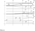
- Fig. 8 illustrates graphs 153, 155, 157, wherein a power in the unit kW, a torque in the unit Nm and a speed in the unit rpm are plotted against time (abscissa 83) during an operating mode change from a parallel hybrid operation to a serial hybrid operation according to an embodiment of the present invention.
- a curve 159 in the graph 153 illustrates a power of the second electric machine 11 or 211
- a curve 161 illustrates a power of the first electric machine 9 or 209
- a curve 163 illustrates a (driving) power of the internal combustion engine 5 or 205
- a curve 165 illustrates a drive power at the drive wheel 15 or 215
- a curve 167 illustrates a power of the accumulator 13 or 213.
- a curve 169 illustrates a torque of the second electric machine 11 or 211
- a curve 171 illustrates a torque of the first electric machine 9 or 209
- a curve 173 illustrates a driving torque of the internal combustion engine 5 or 205
- a curve 175 illustrates a torque for increasing the speed of the internal combustion engine 5 or 205
- a curve 177 illustrates a drive torque at the drive wheel 15 or 215.
- a curve 179 illustrates a rotational speed of the second electric machine 11 or 211
- a curve 181 illustrates a rotational speed of the first electric machine 9 or 209
- a curve 183 illustrates a rotational speed of the internal combustion engine 5 or 205
- a curve 185 illustrates a rotational speed of the drive wheel 15 or 215.
- curves that are temporarily congruent are (partially) plotted with slight distances from each other with respect to the abscissas.
- the operating mode is parallel hybrid operation (with load point increase in the Fig. 8 illustrated embodiment), which is presented via the internal combustion engine.
- the illustrated embodiment involves driving at a constant driving speed, i.e. the drive wheel speed and drive wheel torque (and consequently also the drive wheel power) are constant.
- the main clutch K0 also referred to as the separating clutch, is closed up to a second point in time t2", and is opened from the second point in time t2".
- the unit comprising the internal combustion engine 5, 205 and the first electric machine 9 or 209 are mechanically firmly coupled to the drive wheel 15 or 215 in terms of their speeds in accordance with the parallel transmission ratio of the internal combustion engine 5, 205 to the drive wheel (or the first electric machine 9 or 209 to the drive wheel 15 or 215).
- the required drive power (as well as the additional recharging power for the accumulator 13 or 213) is provided by the internal combustion engine 5, 205.
- the first electric machine 9 or 209 provides a generator torque to implement the load point increase (recharging of the accumulator 13 or 213).
- the change of operating mode from parallel hybrid operation to serial hybrid operation begins at a further first point in time t1" with a command to change the operating mode given by the hybrid coordinator.
- the parallel hybrid operation is first switched to serial hybrid operation (power-split hybrid operation) up to a further second point in time t2".
- the control of the first electric machine 9 or 209 continuously builds up additional generator torque.
- combustion engine power can then be continuously converted into electrical power, which (while maintaining the optional recharging of the accumulator 13 or 213) is transferred directly to the drive motor to represent the wheel power or to represent the required drive power.
- the mechanical power transmission via the main clutch K0 can be gradually reduced to zero to represent the required drive power, until the second time t2" the required drive power is provided exclusively via a serial hybrid operation (with load point increase).
- the operating mode change can be carried out without the optionally possible load point increase.
- the main clutch K0 is completely load-free and can therefore be opened.
- the speed of the internal combustion engine 5 or 205 is transferred to the target speed 187 for serial hybrid operation (operating point setting VM).
- the internal combustion engine 5, 205 provides additional torque via its own fuel injection to increase the speed of the unit consisting of the internal combustion engine 5 or 205 and the first electric machine 9 or 209.
- the target speed of the internal combustion engine for serial hybrid operation has been set with correspondingly changed torques of the internal combustion engine 5 or 205 and the first electric machine 9 or 209.
- the required internal combustion engine torque for increasing the speed can be reduced again.
- the change in operating mode from a parallel hybrid drive to a serial hybrid drive is completed at the third point in time t3". From the third point in time t3", the operating mode is therefore serial hybrid operation (with load point increase).
- the drive wheel speed and drive wheel torque (and consequently also the drive wheel power) remain constant, so that the operating mode change from parallel hybrid operation to serial hybrid operation can be carried out without an interruption in traction.
- the entire process will generally not take more than about 0.2 to 0.5 seconds (duration from the first time t1" to the third time t3”) and can therefore be implemented very quickly.
- Fig. 6 and/or 7 and/or 8 illustrated steps for performing a change from a first operating mode to a second operating mode can be carried out in the Fig. 1 or 2 illustrated hybrid vehicles (e.g. in any order one after the other).
Landscapes
- Engineering & Computer Science (AREA)
- Chemical & Material Sciences (AREA)
- Combustion & Propulsion (AREA)
- Transportation (AREA)
- Mechanical Engineering (AREA)
- Automation & Control Theory (AREA)
- Electric Propulsion And Braking For Vehicles (AREA)
Applications Claiming Priority (3)
| Application Number | Priority Date | Filing Date | Title |
|---|---|---|---|
| DE102015222692.1A DE102015222692A1 (de) | 2015-11-17 | 2015-11-17 | Betreiben einer Antriebseinrichtung eines Hybridfahrzeuges und Hybridfahrzeug |
| EP16793813.3A EP3377353B1 (fr) | 2015-11-17 | 2016-11-03 | Procédé de contrôle d'un dispositif de propulsion d'un véhicule hybride et véhicule hybride |
| PCT/EP2016/076581 WO2017084888A1 (fr) | 2015-11-17 | 2016-11-03 | Procédé permettant de faire fonctionner un dispositif d'entraînement d'un véhicule hybride et véhicule hybride |
Related Parent Applications (1)
| Application Number | Title | Priority Date | Filing Date |
|---|---|---|---|
| EP16793813.3A Division EP3377353B1 (fr) | 2015-11-17 | 2016-11-03 | Procédé de contrôle d'un dispositif de propulsion d'un véhicule hybride et véhicule hybride |
Publications (1)
| Publication Number | Publication Date |
|---|---|
| EP4470813A1 true EP4470813A1 (fr) | 2024-12-04 |
Family
ID=57256284
Family Applications (2)
| Application Number | Title | Priority Date | Filing Date |
|---|---|---|---|
| EP24184240.0A Pending EP4470813A1 (fr) | 2015-11-17 | 2016-11-03 | Procédé de contrôle d'un dispositif de propulsion d'un véhicule hybride et véhicule hybride |
| EP16793813.3A Active EP3377353B1 (fr) | 2015-11-17 | 2016-11-03 | Procédé de contrôle d'un dispositif de propulsion d'un véhicule hybride et véhicule hybride |
Family Applications After (1)
| Application Number | Title | Priority Date | Filing Date |
|---|---|---|---|
| EP16793813.3A Active EP3377353B1 (fr) | 2015-11-17 | 2016-11-03 | Procédé de contrôle d'un dispositif de propulsion d'un véhicule hybride et véhicule hybride |
Country Status (4)
| Country | Link |
|---|---|
| EP (2) | EP4470813A1 (fr) |
| CN (1) | CN108349369B (fr) |
| DE (1) | DE102015222692A1 (fr) |
| WO (1) | WO2017084888A1 (fr) |
Families Citing this family (29)
| Publication number | Priority date | Publication date | Assignee | Title |
|---|---|---|---|---|
| DE102017218855B4 (de) * | 2017-10-23 | 2024-07-18 | Audi Ag | Dynamisch bestimmte Zustartleistung für einen Verbrennungsmotor eines Hybridfahrzeugs |
| DE102017127695A1 (de) | 2017-11-23 | 2019-05-23 | Schaeffler Technologies AG & Co. KG | Hybrid-Antriebsstrang mit zwei elektrischen Maschinen und einer Verbrennungskraftmaschine |
| DE102018103245A1 (de) | 2017-11-29 | 2019-05-29 | Schaeffler Technologies AG & Co. KG | Antriebseinheit für Hybridkraftfahrzeug mit variabler Abtriebsübersetzung |
| DE102018103336A1 (de) | 2018-02-14 | 2019-08-14 | Schaeffler Technologies AG & Co. KG | Hybridmodul und Antriebsanordnung für ein Kraftfahrzeug |
| JP7041397B2 (ja) * | 2018-03-20 | 2022-03-24 | マツダ株式会社 | 車両駆動装置 |
| DE102018114382A1 (de) | 2018-06-15 | 2019-12-19 | Schaeffler Technologies AG & Co. KG | Antriebseinheit für einen Antriebsstrang eines elektrisch antreibbaren Kraftfahrzeugs und Antriebsanordnung |
| DE102018114787A1 (de) | 2018-06-20 | 2019-12-24 | Schaeffler Technologies AG & Co. KG | Antriebseinheit, Antriebsanordnung und Hybrid-Kraftfahrzeug |
| DE102018114790A1 (de) | 2018-06-20 | 2019-12-24 | Schaeffler Technologies AG & Co. KG | Elektrische Antriebseinrichtung, Antriebseinheit und Antriebsanordnung |
| DE102018114798A1 (de) | 2018-06-20 | 2019-12-24 | Schaeffler Technologies AG & Co. KG | Antriebseinheit für einen Antriebsstrang eines elektrisch antreibbaren Kraftfahrzeugs sowie damit ausgestattete Antriebsanordnung und Kraftfahrzeug |
| DE102018114789A1 (de) | 2018-06-20 | 2019-12-24 | Schaeffler Technologies AG & Co. KG | Antriebseinheit für einen Antriebsstrang eines elektrisch antreibbaren Kraftfahrzeugs sowie damit ausgestattete Antriebsanordnung |
| DE102018114782A1 (de) | 2018-06-20 | 2019-12-24 | Schaeffler Technologies AG & Co. KG | Antriebseinheit und Antriebsanordnung |
| DE102018114794A1 (de) | 2018-06-20 | 2019-12-24 | Schaeffler Technologies AG & Co. KG | Antriebseinheit für einen Antriebsstrang eines elektrisch antreibbaren Kraftfahrzeugs und Antriebsanordnung |
| DE102018114784A1 (de) | 2018-06-20 | 2019-12-24 | Schaeffler Technologies AG & Co. KG | Elektrische Rotationsmaschine, Antriebseinheit und Antriebsanordnung |
| DE102018212925B4 (de) | 2018-08-02 | 2021-05-27 | Audi Ag | Verfahren zum Betreiben einer Hybridantriebseinrichtung für ein Kraftfahrzeug sowie entsprechende Hybridantriebseinrichtung |
| DE102018120953A1 (de) | 2018-08-28 | 2020-03-05 | Schaeffler Technologies AG & Co. KG | Hydrauliksystem und Antriebseinheit |
| DE102019120785A1 (de) | 2019-08-01 | 2021-02-04 | Schaeffler Technologies AG & Co. KG | Elektrische Antriebseinheit, Hybridmodul und Antriebsanordnung für ein Kraftfahrzeug |
| DE102019120787A1 (de) | 2019-08-01 | 2021-02-04 | Schaeffler Technologies AG & Co. KG | Elektrische Antriebseinheit, Hybridmodul und Antriebsanordnung für ein Kraftfahrzeug |
| DE102019124254A1 (de) | 2019-09-10 | 2021-03-11 | Schaeffler Technologies AG & Co. KG | Drehmoment-Übertragungssystem, Antriebseinheit und Antriebsanordnung |
| DE102020107299A1 (de) | 2020-03-17 | 2021-09-23 | Volkswagen Aktiengesellschaft | Verfahren zum Betreiben eines hybriden Antriebssystems eines Kraftfahrzeugs, Antriebssystem und Kraftfahrzeug |
| CN112810599B (zh) * | 2020-04-17 | 2022-04-12 | 长城汽车股份有限公司 | 车辆驱动控制方法、系统 |
| DE102021200855A1 (de) | 2021-02-01 | 2022-08-04 | Vitesco Technologies GmbH | Verfahren zum Wechsel von elektrischem Betrieb in den hybridischen Betrieb eines Fahrzeug-Hybridantriebs und Fahrzeug-Hybridantrieb |
| DE102021102915A1 (de) | 2021-02-09 | 2022-08-11 | Audi Aktiengesellschaft | Hybridantriebsstrang für ein hybridgetriebenes Fahrzeug |
| DE102021102914A1 (de) | 2021-02-09 | 2022-08-11 | Audi Aktiengesellschaft | Hybridantriebsstrang für ein hybridgetriebenes Fahrzeug |
| CN113386730B (zh) * | 2021-07-19 | 2023-01-06 | 中国第一汽车股份有限公司 | 混合动力汽车串并联驱动模式切换的控制方法 |
| DE102022104815A1 (de) | 2022-03-01 | 2023-09-07 | Schaeffler Technologies AG & Co. KG | Verfahren zur Steuerung eines Hybridantriebsstrangs |
| DE102022106043A1 (de) | 2022-03-16 | 2023-09-21 | Schaeffler Technologies AG & Co. KG | Batterieladezustandsabhängige Leistungsanforderung bei Verfahren zum Betreiben eines Hybridfahrzeugantriebsstrangs, computerlesbares Speichermedium und Hybridfahrzeugantriebsstrang |
| DE102022106371A1 (de) * | 2022-03-18 | 2023-09-21 | Schaeffler Technologies AG & Co. KG | Verfahren zum Starten einer Verbrennungskraftmaschine eines Hybridfahrzeugs, computerlesbares Speichermedium und Hybridfahrzeugantriebstrang |
| CN116394917B (zh) * | 2023-03-31 | 2025-07-29 | 重庆长安汽车股份有限公司 | 一种混动车辆的串并联驱动模式切换控制方法、装置、车辆、设备及介质 |
| CN116476624B (zh) * | 2023-06-26 | 2023-09-12 | 中国第一汽车股份有限公司 | 一种混合动力控制系统及车辆 |
Citations (13)
| Publication number | Priority date | Publication date | Assignee | Title |
|---|---|---|---|---|
| EP0965475A2 (fr) * | 1998-06-15 | 1999-12-22 | Nissan Motor Co., Ltd. | Procédé d'embrayage pour véhicule hybride |
| DE19532325C2 (de) * | 1995-09-01 | 2001-07-19 | Daimler Chrysler Ag | Verfahren zum Betrieb eines Serienhybridantriebs |
| DE102005033723A1 (de) * | 2005-07-15 | 2007-02-01 | Daimlerchrysler Ag | Antriebsstrang und Verfahren zur Regelung eines Antriesstranges |
| DE102007054368A1 (de) | 2006-11-17 | 2008-06-05 | GM Global Technology Operations, Inc., Detroit | Steuerarchitektur zur Auswahl eines optimalen Modus oder einer optimalen Übersetzung und Antriebsdrehzahl für ein Hybridantriebsstrangsystem |
| DE60223850T2 (de) | 2001-10-22 | 2008-11-13 | Toyota Jidosha Kabushiki Kaisha, Toyota-shi | Verfahren zum Betrieb eines Antriebssystems eines Hybridfahrzeuges |
| US20090166113A1 (en) * | 2007-12-27 | 2009-07-02 | Byd Co. Ltd. | Hybrid Vehicle Having Engagable Clutch Assembly Coupled Between Engine And Traction Motor |
| EP1074087B1 (fr) | 1998-04-21 | 2009-11-25 | The Regents of the University of California | Procede et dispositif de regulation pour vehicules electriques hybrides a moteur a combustion interne |
| EP2127984A1 (fr) * | 2006-12-27 | 2009-12-02 | Bosch Corporation | Procédé permettant de commander un véhicule hybride |
| DE102009019485A1 (de) | 2008-12-09 | 2010-06-10 | Isatec Gmbh | Antriebsstrang mit einem ersten Elektromotor und einem Planetengetriebe sowie Windenergieanlagen, Gasturbinen und Wasserturbinen und Fahrzeuge, die diesen Antriebsstrang aufweisen |
| US20120245785A1 (en) * | 2009-12-16 | 2012-09-27 | Honda Motor Co., Ltd. | Hybrid vehicle and control method thereof |
| DE102012103292A1 (de) | 2012-04-17 | 2013-10-17 | Dr. Ing. H.C. F. Porsche Aktiengesellschaft | Verfahren zum Betrieb eines elektrischen Antriebsstranges eines Fahrzeuges sowie elektrischer Antriebsstrang für ein Fahrzeug |
| DE102013001095A1 (de) | 2013-01-23 | 2014-07-24 | Audi Ag | Verfahren zum Betreiben einer Hybridantriebseinrichtung eines Kraftfahrzeugs, entsprechende Hybridantriebseinrichtung sowie Kraftfahrzeug |
| US20150232082A1 (en) * | 2013-02-08 | 2015-08-20 | Efficient Drivetrains, Inc. | Systems and methods for implementing dynamic operating modes and control policies for hybrid electric vehicles |
Family Cites Families (21)
| Publication number | Priority date | Publication date | Assignee | Title |
|---|---|---|---|---|
| AU6019299A (en) * | 1998-09-14 | 2000-04-03 | Paice Corporation | Hybrid vehicles |
| JP4134977B2 (ja) * | 2004-10-27 | 2008-08-20 | 日産自動車株式会社 | ハイブリッド変速機のモード切り替え制御装置 |
| JP4167667B2 (ja) * | 2005-03-24 | 2008-10-15 | ヤマハ発動機株式会社 | ハイブリッド二輪車 |
| US7833119B2 (en) * | 2005-09-23 | 2010-11-16 | Gm Global Technology Corporation, Inc. | Powertrain with series electric launch and electric power assisted performance |
| DE102006005468B4 (de) * | 2006-02-07 | 2017-09-21 | Zf Friedrichshafen Ag | Verfahren zum Betreiben eines Parallelhybridantriebsstranges eines Fahrzeuges |
| DE102007055827A1 (de) * | 2007-12-17 | 2009-06-18 | Zf Friedrichshafen Ag | Verfahren und Vorrichtung zum Betrieb eines Hybridantriebes eines Fahrzeuges |
| JP2011143754A (ja) * | 2010-01-12 | 2011-07-28 | Toyota Motor Corp | ハイブリッド車の駆動装置 |
| CN102862469B (zh) * | 2011-07-04 | 2016-05-18 | 科力远混合动力技术有限公司 | 混合动力驱动装置、驱动方法及混合动力汽车 |
| DE102011079079A1 (de) * | 2011-07-13 | 2013-01-17 | Zf Friedrichshafen Ag | Verfahren zur Steuerung eines Hybridantriebsstrangs eines Kraftfahrzeugs |
| JP5845827B2 (ja) * | 2011-11-07 | 2016-01-20 | トヨタ自動車株式会社 | ハイブリッド車両 |
| DE102011086291A1 (de) * | 2011-11-14 | 2013-05-16 | Steyr Motors Gmbh | Steuerverfahren eines hybriden Schiffsantriebes und hybride Antriebsanlage |
| JP5783105B2 (ja) * | 2012-03-27 | 2015-09-24 | トヨタ自動車株式会社 | ハイブリッド車両 |
| DE102012016988A1 (de) * | 2012-08-25 | 2014-05-15 | Volkswagen Aktiengesellschaft | Hybridantriebsstrang für ein Kraftfahrzeug, Hybridfahrzeug und dessen Verwendung |
| CN103072461B (zh) * | 2013-01-22 | 2015-11-18 | 郑州宇通客车股份有限公司 | 双电机多模式混合动力驱动系统及其控制方法 |
| WO2014118950A1 (fr) * | 2013-01-31 | 2014-08-07 | トヨタ自動車株式会社 | Dispositif de commande pour véhicule hybride |
| CN204136757U (zh) * | 2013-02-08 | 2015-02-04 | 高效动力传动系统公司 | 用于双电机双离合混合动力车的动力系统配置及双电机双离合混合动力车 |
| JP5825288B2 (ja) * | 2013-04-08 | 2015-12-02 | トヨタ自動車株式会社 | ハイブリッド車両 |
| KR20150142052A (ko) * | 2013-05-13 | 2015-12-21 | 도요타 지도샤(주) | 하이브리드 차량의 구동 장치 |
| KR101491251B1 (ko) * | 2013-05-22 | 2015-02-11 | 현대자동차주식회사 | 하이브리드 차량용 동력전달장치 |
| JP6176122B2 (ja) * | 2014-01-14 | 2017-08-09 | トヨタ自動車株式会社 | 車両制御装置 |
| CN104924889B (zh) * | 2015-06-30 | 2017-08-22 | 天津清源电动车辆有限责任公司 | 一种混合动力系统和混合动力车辆及混合驱动方法 |
-
2015
- 2015-11-17 DE DE102015222692.1A patent/DE102015222692A1/de active Pending
-
2016
- 2016-11-03 WO PCT/EP2016/076581 patent/WO2017084888A1/fr not_active Ceased
- 2016-11-03 CN CN201680067237.9A patent/CN108349369B/zh active Active
- 2016-11-03 EP EP24184240.0A patent/EP4470813A1/fr active Pending
- 2016-11-03 EP EP16793813.3A patent/EP3377353B1/fr active Active
Patent Citations (13)
| Publication number | Priority date | Publication date | Assignee | Title |
|---|---|---|---|---|
| DE19532325C2 (de) * | 1995-09-01 | 2001-07-19 | Daimler Chrysler Ag | Verfahren zum Betrieb eines Serienhybridantriebs |
| EP1074087B1 (fr) | 1998-04-21 | 2009-11-25 | The Regents of the University of California | Procede et dispositif de regulation pour vehicules electriques hybrides a moteur a combustion interne |
| EP0965475A2 (fr) * | 1998-06-15 | 1999-12-22 | Nissan Motor Co., Ltd. | Procédé d'embrayage pour véhicule hybride |
| DE60223850T2 (de) | 2001-10-22 | 2008-11-13 | Toyota Jidosha Kabushiki Kaisha, Toyota-shi | Verfahren zum Betrieb eines Antriebssystems eines Hybridfahrzeuges |
| DE102005033723A1 (de) * | 2005-07-15 | 2007-02-01 | Daimlerchrysler Ag | Antriebsstrang und Verfahren zur Regelung eines Antriesstranges |
| DE102007054368A1 (de) | 2006-11-17 | 2008-06-05 | GM Global Technology Operations, Inc., Detroit | Steuerarchitektur zur Auswahl eines optimalen Modus oder einer optimalen Übersetzung und Antriebsdrehzahl für ein Hybridantriebsstrangsystem |
| EP2127984A1 (fr) * | 2006-12-27 | 2009-12-02 | Bosch Corporation | Procédé permettant de commander un véhicule hybride |
| US20090166113A1 (en) * | 2007-12-27 | 2009-07-02 | Byd Co. Ltd. | Hybrid Vehicle Having Engagable Clutch Assembly Coupled Between Engine And Traction Motor |
| DE102009019485A1 (de) | 2008-12-09 | 2010-06-10 | Isatec Gmbh | Antriebsstrang mit einem ersten Elektromotor und einem Planetengetriebe sowie Windenergieanlagen, Gasturbinen und Wasserturbinen und Fahrzeuge, die diesen Antriebsstrang aufweisen |
| US20120245785A1 (en) * | 2009-12-16 | 2012-09-27 | Honda Motor Co., Ltd. | Hybrid vehicle and control method thereof |
| DE102012103292A1 (de) | 2012-04-17 | 2013-10-17 | Dr. Ing. H.C. F. Porsche Aktiengesellschaft | Verfahren zum Betrieb eines elektrischen Antriebsstranges eines Fahrzeuges sowie elektrischer Antriebsstrang für ein Fahrzeug |
| DE102013001095A1 (de) | 2013-01-23 | 2014-07-24 | Audi Ag | Verfahren zum Betreiben einer Hybridantriebseinrichtung eines Kraftfahrzeugs, entsprechende Hybridantriebseinrichtung sowie Kraftfahrzeug |
| US20150232082A1 (en) * | 2013-02-08 | 2015-08-20 | Efficient Drivetrains, Inc. | Systems and methods for implementing dynamic operating modes and control policies for hybrid electric vehicles |
Also Published As
| Publication number | Publication date |
|---|---|
| WO2017084888A1 (fr) | 2017-05-26 |
| CN108349369B (zh) | 2021-08-13 |
| EP3377353B1 (fr) | 2024-06-26 |
| DE102015222692A1 (de) | 2017-05-18 |
| CN108349369A (zh) | 2018-07-31 |
| EP3377353A1 (fr) | 2018-09-26 |
Similar Documents
| Publication | Publication Date | Title |
|---|---|---|
| EP3377353B1 (fr) | Procédé de contrôle d'un dispositif de propulsion d'un véhicule hybride et véhicule hybride | |
| DE102015222690B4 (de) | Steuern einer Antriebseinrichtung eines Hybridfahrzeuges und Hybridfahrzeug | |
| EP3377378B1 (fr) | Procédé de contrôle d'un dispositif de propulsion d'un véhicule hybride et véhicule hybride | |
| EP3377379B1 (fr) | Procédé de commande d'un dispositif d'entraînement d'un véhicule hybride et véhicule hybride | |
| EP1485266B1 (fr) | Procede pour commander l'entrainement hybride d'un vehicule | |
| DE102009037195B4 (de) | Steuerungssystem und Verfahren zur Drehmomentverwaltung bei einem Hybridfahrzeug, das mit variabler Zylinderabschaltung ausgestattet ist | |
| DE112011104861B4 (de) | Antriebsquellensteuervorrichtung für Hybridkraftfahrzeug und Antriebsquellensteuerverfahren für Hybridkraftfahrzeug und Hybridkraftfahrzeug | |
| DE102007038585A1 (de) | Verfahren zur Lastpunktverschiebung im Hybridbetrieb bei einem parallelen Hybridfahrzeug | |
| DE102015206061A1 (de) | Stufengetriebesteuerung für ein hybridfahrzeug | |
| DE102008027658A1 (de) | Verfahren zum Starten einer Brennkraftmaschine eines Hybridfahrzeugs | |
| DE102008053505A1 (de) | Verfahren zur Steuerung eines Hybridantriebsstrangs eines Kraftfahrzeuges | |
| DE102013104430A1 (de) | Traktionssteuersystem für ein Hybridfahrzeug | |
| DE112011104840T5 (de) | Antriebssteuervorrichtung und Verfahren zum Bereitstellen einer Antriebssteuerung für ein Hybridfahrzeug und Hybridfahrzeug | |
| DE102013106324A1 (de) | Verfahren und System zur Erwärmung der Traktionsbatterie eines Elektrofahrzeugs | |
| DE102016014178A1 (de) | Antriebsbaugruppe eines Fahrzeugs mit Hybridantrieb und deren Steuerungsverfahren und Steuereinrichtung | |
| DE112011104809T5 (de) | Antriebssteuervorrichtung und Antriebssteuerverfahren für Hybridfahrzeuge und Hybridfahrzeug | |
| DE102022124814A1 (de) | Hybridelektrofahrzeug und Verfahren zum Steuern des Elektromotors von diesem | |
| DE102021101068A1 (de) | Batterieleistungssteuersystem für hybrid-/elektrofahrzeuge | |
| DE102005037713A1 (de) | Antriebsstrang für ein Kraftfahrzeug sowie Verfahren zum Betreiben eines Antriebsstranges | |
| EP1755912B1 (fr) | Procede permettant de faire fonctionner un vehicule automobile hybride | |
| WO2008015049A1 (fr) | Dispositif de commande d'un groupe propulseur hybride | |
| EP3592588A1 (fr) | Procédé de commande d'un véhicule à moteur et véhicule à moteur | |
| DE102005044828A1 (de) | Verfahren und Vorrichtung zur Ermittlung eines optimalen Betriebspunktes bei Fahrzeugen mit Hybridantrieb | |
| DE102019203985A1 (de) | Verfahren zum Steuern eines Antriebsstrangs, Steuerung, Antriebsstrang und Kraftfahrzeug | |
| DE102016118756A1 (de) | Verfahren zum Anfahren eines Kraftfahrzeuges |
Legal Events
| Date | Code | Title | Description |
|---|---|---|---|
| PUAI | Public reference made under article 153(3) epc to a published international application that has entered the european phase |
Free format text: ORIGINAL CODE: 0009012 |
|
| STAA | Information on the status of an ep patent application or granted ep patent |
Free format text: STATUS: THE APPLICATION HAS BEEN PUBLISHED |
|
| AC | Divisional application: reference to earlier application |
Ref document number: 3377353 Country of ref document: EP Kind code of ref document: P |
|
| AK | Designated contracting states |
Kind code of ref document: A1 Designated state(s): AL AT BE BG CH CY CZ DE DK EE ES FI FR GB GR HR HU IE IS IT LI LT LU LV MC MK MT NL NO PL PT RO RS SE SI SK SM TR |
|
| STAA | Information on the status of an ep patent application or granted ep patent |
Free format text: STATUS: REQUEST FOR EXAMINATION WAS MADE |
|
| 17P | Request for examination filed |
Effective date: 20250604 |
|
| STAA | Information on the status of an ep patent application or granted ep patent |
Free format text: STATUS: EXAMINATION IS IN PROGRESS |
|
| 17Q | First examination report despatched |
Effective date: 20260210 |