EP4470818A1 - Unité de transport à lévitation magnétique, dispositif de transport avec un ensemble stator et au moins une unité de transport à lévitation magnétique, installation de production et procédé de couplage énergétique d'une unité de transport - Google Patents
Unité de transport à lévitation magnétique, dispositif de transport avec un ensemble stator et au moins une unité de transport à lévitation magnétique, installation de production et procédé de couplage énergétique d'une unité de transport Download PDFInfo
- Publication number
- EP4470818A1 EP4470818A1 EP23176671.8A EP23176671A EP4470818A1 EP 4470818 A1 EP4470818 A1 EP 4470818A1 EP 23176671 A EP23176671 A EP 23176671A EP 4470818 A1 EP4470818 A1 EP 4470818A1
- Authority
- EP
- European Patent Office
- Prior art keywords
- transport unit
- unit
- magnetically
- levitable
- transport
- Prior art date
- Legal status (The legal status is an assumption and is not a legal conclusion. Google has not performed a legal analysis and makes no representation as to the accuracy of the status listed.)
- Pending
Links
Images


Classifications
-
- B—PERFORMING OPERATIONS; TRANSPORTING
- B60—VEHICLES IN GENERAL
- B60L—PROPULSION OF ELECTRICALLY-PROPELLED VEHICLES; SUPPLYING ELECTRIC POWER FOR AUXILIARY EQUIPMENT OF ELECTRICALLY-PROPELLED VEHICLES; ELECTRODYNAMIC BRAKE SYSTEMS FOR VEHICLES IN GENERAL; MAGNETIC SUSPENSION OR LEVITATION FOR VEHICLES; MONITORING OPERATING VARIABLES OF ELECTRICALLY-PROPELLED VEHICLES; ELECTRIC SAFETY DEVICES FOR ELECTRICALLY-PROPELLED VEHICLES
- B60L13/00—Electric propulsion for monorail vehicles, suspension vehicles or rack railways; Magnetic suspension or levitation for vehicles
- B60L13/10—Combination of electric propulsion and magnetic suspension or levitation
-
- B—PERFORMING OPERATIONS; TRANSPORTING
- B60—VEHICLES IN GENERAL
- B60L—PROPULSION OF ELECTRICALLY-PROPELLED VEHICLES; SUPPLYING ELECTRIC POWER FOR AUXILIARY EQUIPMENT OF ELECTRICALLY-PROPELLED VEHICLES; ELECTRODYNAMIC BRAKE SYSTEMS FOR VEHICLES IN GENERAL; MAGNETIC SUSPENSION OR LEVITATION FOR VEHICLES; MONITORING OPERATING VARIABLES OF ELECTRICALLY-PROPELLED VEHICLES; ELECTRIC SAFETY DEVICES FOR ELECTRICALLY-PROPELLED VEHICLES
- B60L1/00—Supplying electric power to auxiliary equipment of vehicles
-
- B—PERFORMING OPERATIONS; TRANSPORTING
- B60—VEHICLES IN GENERAL
- B60L—PROPULSION OF ELECTRICALLY-PROPELLED VEHICLES; SUPPLYING ELECTRIC POWER FOR AUXILIARY EQUIPMENT OF ELECTRICALLY-PROPELLED VEHICLES; ELECTRODYNAMIC BRAKE SYSTEMS FOR VEHICLES IN GENERAL; MAGNETIC SUSPENSION OR LEVITATION FOR VEHICLES; MONITORING OPERATING VARIABLES OF ELECTRICALLY-PROPELLED VEHICLES; ELECTRIC SAFETY DEVICES FOR ELECTRICALLY-PROPELLED VEHICLES
- B60L5/00—Current collectors for power supply lines of electrically-propelled vehicles
- B60L5/005—Current collectors for power supply lines of electrically-propelled vehicles without mechanical contact between the collector and the power supply line
-
- B—PERFORMING OPERATIONS; TRANSPORTING
- B65—CONVEYING; PACKING; STORING; HANDLING THIN OR FILAMENTARY MATERIAL
- B65G—TRANSPORT OR STORAGE DEVICES, e.g. CONVEYORS FOR LOADING OR TIPPING, SHOP CONVEYOR SYSTEMS OR PNEUMATIC TUBE CONVEYORS
- B65G54/00—Non-mechanical conveyors not otherwise provided for
- B65G54/02—Non-mechanical conveyors not otherwise provided for electrostatic, electric, or magnetic
-
- H—ELECTRICITY
- H02—GENERATION; CONVERSION OR DISTRIBUTION OF ELECTRIC POWER
- H02J—ELECTRIC POWER NETWORKS; CIRCUIT ARRANGEMENTS OR SYSTEMS FOR SUPPLYING OR DISTRIBUTING ELECTRIC POWER; SYSTEMS FOR STORING ELECTRIC ENERGY
- H02J50/00—Circuit arrangements or systems for wireless supply or distribution of electric power
- H02J50/10—Circuit arrangements or systems for wireless supply or distribution of electric power using inductive coupling
- H02J50/12—Circuit arrangements or systems for wireless supply or distribution of electric power using inductive coupling of the resonant type
-
- B—PERFORMING OPERATIONS; TRANSPORTING
- B60—VEHICLES IN GENERAL
- B60L—PROPULSION OF ELECTRICALLY-PROPELLED VEHICLES; SUPPLYING ELECTRIC POWER FOR AUXILIARY EQUIPMENT OF ELECTRICALLY-PROPELLED VEHICLES; ELECTRODYNAMIC BRAKE SYSTEMS FOR VEHICLES IN GENERAL; MAGNETIC SUSPENSION OR LEVITATION FOR VEHICLES; MONITORING OPERATING VARIABLES OF ELECTRICALLY-PROPELLED VEHICLES; ELECTRIC SAFETY DEVICES FOR ELECTRICALLY-PROPELLED VEHICLES
- B60L2200/00—Type of vehicles
- B60L2200/36—Vehicles designed to transport cargo, e.g. trucks
-
- B—PERFORMING OPERATIONS; TRANSPORTING
- B60—VEHICLES IN GENERAL
- B60L—PROPULSION OF ELECTRICALLY-PROPELLED VEHICLES; SUPPLYING ELECTRIC POWER FOR AUXILIARY EQUIPMENT OF ELECTRICALLY-PROPELLED VEHICLES; ELECTRODYNAMIC BRAKE SYSTEMS FOR VEHICLES IN GENERAL; MAGNETIC SUSPENSION OR LEVITATION FOR VEHICLES; MONITORING OPERATING VARIABLES OF ELECTRICALLY-PROPELLED VEHICLES; ELECTRIC SAFETY DEVICES FOR ELECTRICALLY-PROPELLED VEHICLES
- B60L2200/00—Type of vehicles
- B60L2200/40—Working vehicles
Definitions
- the invention relates to a magnetically levitable transport unit.
- the invention further relates to a transport device with a stator arrangement and at least one magnetically levitable transport unit, in particular a mover, which can be moved on at least one sector of the stator arrangement.
- the invention also relates to a production plant, preferably for the manufacture of pharmaceutical products.
- the invention further relates to a method for the energetic coupling of a magnetically levitable transport unit.
- the invention relates to a use of an energy transfer on a magnetically levitable transport unit.
- Levitable transport units are known and are used, for example, to move and/or hold a payload in a controlled manner using a coil field and/or a permanent magnetic arrangement that can be arranged in a drive surface.
- the drive surface can be aligned horizontally, vertically or in any direction. The drive surface thus provides a stator arrangement or a levitation generator.
- levitation can be characterized, for example, by the fact that a A transport unit equipped with permanent magnets or otherwise magnetically active is suspended in a controlled magnetic field and/or is moved by controlled changes in the magnetic field.
- This stationary magnetic field can be provided, for example, with a levitation generator.
- a controlled magnetic field on the movable transport unit for example by energizing coils and/or moving permanent magnets, in order to levitate in a controlled manner in a temporally constant magnetic field of the levitation generator and to move the transport unit in a controlled manner.
- the invention is based on the object of equipping a magnetically levitable transport unit with additional functionalities.
- the invention proposes the features of claim 1.
- the invention proposes a magnetically levitable transport unit with an electrical functional unit that can preferably be supplied inductively and/or galvanically.
- the invention therefore generally proposes the provision of an additional energy supply path, which is decoupled from a drive movement of the transport unit, for supplying an electrical functional unit on the transport unit. For example, it can be provided that this energy supply path remains active even when a drive of the levitable transport unit is switched off.
- the electrical functional unit can be supplied with energy, in particular galvanically, via electrical contacts.
- a contactless or non-contact energy exchange can thus take place between the electrical functional unit of the magnetically levitable transport unit and another electrical functional unit which, for example, draws electrical energy from a stationary energy source and/or feed unit and transmits it to the electrical functional unit of the transport unit.
- the invention proposes that the electrical functional unit has an electrical storage unit. This means that the functional unit can also be operated outside of a zone of electrical supply and/or coupling.
- the electrical storage unit is a rechargeable galvanic element, in particular an accumulator. Furthermore, it can be provided, for example, that the electrical storage unit is a capacitor.
- the storage unit can also be attached as a non-rechargeable storage unit, preferably in an exchangeable manner.
- An exchangeable storage unit can also be used, which can be unloaded and/or charged outside the transport unit.
- the electrical storage unit can be charged by means of direct current rapid charging, which in turn advantageously allows short charging times and thus correlating short downtimes of the magnetically levitable transport unit to be achieved.
- the electrical functional unit has an electrical consumer.
- the electrical energy which is preferably absorbed inductively, can be converted, for example, directly and/or continuously into kinetic energy and/or potential energy.
- the invention proposes that the electrical functional unit has a power receiving unit.
- the power receiving unit is designed to receive a power, preferably an electrical power, in particular inductively and contactlessly and/or galvanically via preferably at least two electrical contacts.
- the power receiving unit receives the electrical power and, for example, operates the electrical consumer directly and/or continuously or can be used in particular to charge the electrical storage unit, which in turn can, for example, provide electrical energy for the electrical consumer.
- the power receiving unit can have at least one inductively coupled resonant circuit and/or at least one contact pair. This means that weakly resonant couplings can be achieved even over a greater distance with an acceptably high level of efficiency. This can be advantageous, for example, if a supply of the functional unit is to be ensured even in a levitated position that is at the maximum distance from a drive surface.
- a galvanic supply of the electrical functional unit can be generated, for example via sliding contacts.
- the power receiving unit can thus receive power over a greater range.
- the levitation the magnetically levitable transport unit is carried out via an electrical energy source that supplies the electrical functional unit, which in turn advantageously enables a higher levitation of the magnetically levitable transport unit with constant power consumption, in particular by the inductively coupled oscillating circuit of the power receiving unit.
- the transport unit is designed with at least one receiving coil.
- a voltage can be induced in the receiving coil, for example by a transmitting coil, which in turn can, for example, charge the electrical storage unit and/or directly drive the electrical consumer.
- the electrical consumer of the magnetically levitable transport unit is at least one drive unit, in particular an electric motor. Complex mechanical work processes can thus be easily implemented on a transport unit.
- the electric motor can, for example, be designed to enable rotating and/or translational movements on the magnetically levitable transport unit.
- the electrical storage unit may be a replaceable battery and/or a battery installed stationary on the transport unit.
- the battery can, for example, supply the electric drive unit.
- the magnetically levitable transport unit outputs and/or processes a signal, for example when a previously defined limit value is reached, which defines a low charge state of the electrical storage unit.
- This also makes it possible to prevent, for example, a failure of the transport unit and initiate a charging process.
- the at least one sensor can also be designed, for example, to determine all other physical properties.
- an optical sensor for example an inspection camera, a A distance sensor, a temperature sensor, a humidity sensor or other sensors can be used.
- the transport unit is designed with a temperature control device.
- the temperature control device can be a device for heating and/or cooling, for example. It is particularly advantageous that various products positioned on the magnetically levitable transport unit, for example pharmaceutical products, can be cooled and/or heated to a certain temperature, which may need to be kept almost constant. Controlled heating can therefore also be carried out, for example before a closure.
- the transport unit is designed with a motor-driven part.
- a motor-driven part can be, for example, a rotary motor, a linear motor or a simple drive form such as a lifting magnet.
- a device that can be positioned on the magnetically levitable transport unit and moved by a motor can be, for example, a labeling system with which, for example, batch numbers can be stored on different containers.
- the motorized driven part is, for example, a robot.
- the motor-driven part is, for example, a gripping element.
- containers can be transferred from one magnetically levitable transport unit to another or further magnetically levitable transport unit and/or picked up by and/or delivered to a process unit via a motor-driven gripping element. It is also advantageous that process sequences can be automated and/or accelerated.
- a process unit can be operated independently to carry out a function.
- Several functional units can be connected by transport units for a flow of goods, for example.
- the process units can be stationary and/or movable, for example.
- the motor-driven part is, for example, a movable container holder.
- containers containing pharmaceutical products can be swivelled and thus precisely controlled and automatically transferred. It is also advantageous if the pharmaceutical products are transported by a controlled handling unit, for example on the transport unit. a process and/or machining unit, which in turn can facilitate processing and/or further processing.
- the robot is designed with a gripping element, for example, which functions as a movable container holder.
- the transport unit is designed with a scale.
- the additional electrical supply can be used, for example, for electronically recording a weight and/or transmitting the recorded measured values.
- containers which can preferably be positioned on the magnetically levitable transport unit can be weighed before and/or after and/or during a filling process.
- the transport unit is designed with a preferably wireless communication unit and/or with a data processing device as an electrical functional unit. This considerably expands the functionality of the transport unit. In a further advantageous embodiment, it can be provided that the transport unit is designed with a particle counter.
- a particle counter can, for example, be used advantageously to monitor possible microbiological contamination, for example within a clean room.
- a container with, for example, a pharmaceutical product is placed on a magnetically levitable transport unit within a clean room is filled, while, for example simultaneously, an air flow of the clean room can be monitored for microbiological contamination by means of the particle counter via a further magnetically levitable transport unit.
- a cleanroom process can, for example, be aseptic filling and/or sealing and/or analysis of pharmaceutical products.
- the transport unit is designed to accommodate at least one decontamination system.
- a decontamination system can be used, for example, to decontaminate clean rooms, especially before a clean room process is carried out. This can advantageously ensure that the clean room is as free as possible from microbiological contamination, for example, at the start of the clean room process.
- the transport unit carries at least one storage container and/or a dispensing unit.
- the transport unit carrying the storage container is additionally designed with the drive unit already mentioned, whereby the storage container and/or the dispensing unit can be moved and/or transferred, for example, from one process unit to a next process unit.
- the transport unit is designed with a movable crimping disk and/or crimping device.
- a closure lid which is placed on a container, can be flanged over a contact and the container can thus be closed.
- the transport unit formed with the movable crimping disk and/or crimping device can be used to precisely define, for example, delivery forces, which in turn can also advantageously generate a high-quality closure of the container.
- the transport unit is designed with a drivable lifting device.
- the drivable lifting device is designed to move a stopper, preferably with a container located on the lifting device.
- the stopper can be used, for example, to seal the container airtight. It is particularly advantageous that the contact pressure of the container can be adjusted using the drivable lifting device of the transport unit.
- the drivable lifting device is designed to move a filling needle, preferably with a container located on the lifting device.
- the syringe can be used, for example, to inject a liquid, for example a fluid pharmaceutical product, into the container. It is particularly advantageous if the container is closed with the stopper after the injection. Alternatively, the container can be closed with the stopper before the liquid is injected, for example, and the syringe can be guided through the stopper, for example, in order to largely prevent contamination of the liquid.
- the drivable lifting device is designed to move a closure lid, preferably with a container located on the lifting device.
- the lifting device of the transport unit in particular after the syringe has started moving, can move the closure lid via the lifting device in order to completely close the container, for example via the or a movable crimping disk and/or crimping device of another transport unit.
- the transport unit is designed with a preferably movable holder for a nutrient medium carrier, in which a nutrient medium can preferably be presented.
- the nutrient medium can be used, for example, in addition to a particle counter, which may be formed on another transport unit, to monitor for microbiological contamination. can be.
- the transport unit is designed with a preferably sealed housing, in particular so that the at least one receiving coil of the magnetically levitable transport unit is protected from contamination.
- the housing is constructed according to "hygienic design” guidelines.
- "Hygienic design” can be understood as the design of parts, components and/or production systems that are easy to clean. It can also be provided that the material of the housing meets requirements for decontaminability and withstands mechanical and chemical stress.
- the transport unit can be sealed gas-tight via the housing.
- the IP protection classes for example according to DIN EN 60529, are used to categorize the tightness of the housing. It can therefore possibly be provided that the housing achieves at least protection class IP67, for example.
- a particular advantage is that the transport unit with the transmitting coil can be protected from microbiological contamination, for example. Another advantage is that the number of decontamination cycles for decontaminating the transport unit can be reduced.
- the invention provides the features of the independent claim directed to a transport device.
- a transport device with a stator arrangement and at least one magnetically levitable transport unit, in particular a mover, which can be moved on at least one sector of the stator arrangement
- the magnetically levitable transport unit is designed with at least one receiving coil and that at least one sector of the stator arrangement is designed with at least one transmitting coil, via which an energetic, preferably contactless and/or inductive, coupling can be formed.
- the stator arrangement can be, for example, a planar motor system with at least one sector. It can be provided, for example, that the magnetically levitable transport unit levitates a few millimeters above the stator arrangement without contact.
- the transmitting coil can, for example, be connected to a stationary energy source and/or feed unit.
- the energetic coupling can also be achieved via galvanic contacts, for example.
- energy in particular electrical energy
- an electrical functional unit of the transport unit for example an electrical consumer, can preferably be driven.
- a preferably resonant inductive coupling and/or a capacitive coupling can be formed between the transport unit and the stator arrangement via the energetic coupling.
- the range of the energy transmission can be increased, which in turn is advantageous in that the levitation of the transport unit on the stator arrangement can be changed, for example, and/or the influence of the levitation on the energy transmission can be reduced.
- the receiving coil of the transport unit is coupled to an oscillating circuit.
- a resonance frequency of the resonant circuit is matched to a transmission frequency, which in turn can advantageously generate a higher efficiency of the energetic coupling.
- a further advantage is that a transmission frequency band for energy transmission to the transport unit can be separated from a levitation frequency band. This means that any impairment of the controlled control of the transport unit(s) by the energy transmission can be reduced or even avoided.
- At least one transmitting coil of the at least one sector of the stator arrangement is connected to a feed unit for impressing a frequency-stabilized and/or amplitude-constant current.
- the frequency stabilization can be used, for example, to form a weakly resonant coupling, the amplitude stabilization to ensure an uninterrupted energy flow even with a high power consumption at the electrical functional unit.
- a preferably electrical storage unit of the transport unit can be charged via the energetic coupling.
- the electrical storage unit can be energetically coupled to an electrical drive unit.
- the electrical storage unit can, for example, be an accumulator.
- the charging of the electrical storage unit takes place via direct current rapid charging.
- the electric drive unit can thus be powered, for example, by the electric storage unit.
- Another particularly advantageous feature is that it enables discontinuous energy supply.
- an energy transmission area is created, for example, at the points where the transmitting coil or the (other) coupling means is formed on the respective sector.
- This energy transmission area can thus be formed, for example, in sections on a single sector, over the entire sector, in sections over several sectors or completely over several sectors.
- all sectors of the stator arrangement are formed with at least one transmitting coil.
- the transmitting coil is formed only in sections on the sectors.
- the transmitting coils of the sectors can be powered independently of each other.
- the energetic coupling is designed to to maintain a continuous energy supply to the transport unit.
- an electrical storage unit which supplies energy to an electrical drive unit of the transport unit, can be dispensed with.
- the energetic coupling between the transport unit and the stator arrangement takes place on a vertical plane.
- a horizontal plane is designed to carry out a process and the vertical plane is designed primarily for the energetic coupling and/or for charging the transport unit. It can also be provided, for example, that the vertical plane is designed to carry out a process and the horizontal plane is designed for the energetic coupling and/or for charging the transport unit.
- transport units that are moved on a horizontal plane are not hindered by an energetic coupling, for example a charging process of another transport unit.
- the features of the independent claim directed to a production plant are provided according to the invention to achieve the above-mentioned object.
- the invention proposes a production plant, preferably for the manufacture of pharmaceutical products, with a controlled room, preferably an isolator and/or RABS and a transport device arranged therein.
- the controlled room can, for example, be a clean room.
- Isolators and RABS are used, for example, in the pharmaceutical industry for the manufacture or aseptic production of pharmaceutical products.
- the transport device can be used to generate automated process sequences or production sequences, for example, in accordance with the advantages already listed.
- the production plant is designed with sectors for charging and/or for energetic coupling to a process unit.
- the energetic coupling and thus the energy for example for driving the electrical consumer of the transport unit, can be constantly ensured at the points where the electrical energy is required to carry out a process.
- the production plant is designed with sectors for charging and/or for energetic coupling at a distance from a process unit.
- the transport unit is designed with an electrical storage unit and, for charging, moves to a sector designed with a transmitting coil for energetic coupling.
- the transport unit to be charged drives to the sector that is spaced apart from the process unit and designed for energy coupling, while a further, preferably already charged transport unit can continue a process to be carried out on the process unit, which is particularly advantageous. It is therefore particularly advantageous that the charging of the transport unit does not hinder the process to be carried out and can promote continuous process execution. It can also be provided, for example, that the transport unit, in particular mover, uses and/or consumes the energy absorbed via the charging directly to carry out a process, for example to drive a movement and/or feed a consumer, in particular converts it into a form of energy necessary to carry out the process.
- the features of the independent claim directed to a method are provided according to the invention to solve the above-mentioned problem.
- a method for energetically coupling a magnetically levitable transport unit to a receiving coil through at least one energy transmission area, in particular a transmitting coil of a sector of a stator arrangement is proposed to solve the above-mentioned problem, wherein an electrical consumer on the transport unit is supplied with energy by at least one sector of the stator arrangement.
- the electrical consumer is an electrical drive unit.
- An electric motor for example, can be used as an electrical drive unit.
- the transport unit is thus movable.
- the movement can be translational and/or rotational, for example.
- the invention proposes a method for the energetic coupling of a magnetically levitable transport unit with a receiving coil by at least one transmitting coil of a sector of a stator arrangement, wherein an electrical storage unit on the transport unit is supplied with energy by at least one sector of the stator arrangement.
- the electrical storage unit can, for example, be an accumulator.
- the electrical storage unit drives the electrical consumer, in particular the electrical drive unit.
- the electrical storage unit drives the electrical consumer, in particular the electrical drive unit.
- a sensor is arranged on the magnetically levitating transport unit, which sensor determines a state, in particular a charge state, of the electrical storage unit and/or a state of the electrical consumer of the transport unit.
- the state of the electrical consumer can be determined and/or identified using a specific physical quantity.
- the physical quantity can be, for example, a rotational speed, a torque, an electrical power, a speed, a frequency, a magnetic flux, a magnetic flux density, an inductance and/or an acceleration, but is not limited to these quantities.
- the senor emits a signal at a predefined (limit) value, which provides information about a minimum or maximum charge level and/or overheating of the electrical storage unit, for example.
- the advantage here is that the signal can be recognized either by an operator and/or, for example, a control unit of the transport unit and appropriate (counter)measures can be initiated.
- the transport unit moves to a sector following a signal from the sensor described and/or claimed herein or from a sensor.
- the transport unit thus automatically drives to a sector to charge the electrical storage unit, for example after the charge level falls below the minimum level.
- the transport unit approaches a sector after a predetermined period of time.
- the time span can, for example, be an empirically determined time between a maximum and a minimum charge level of the electrical storage unit.
- the time span can therefore advantageously be used as a reference value for the charge level.
- the transport unit moves to a sector after a predetermined consumption.
- the specified consumption can, for example, be a predefined difference value of the charge level of the electrical storage unit at which the electrical storage unit of the transport unit is to be charged.
- a process unit can also be approached by the transport unit.
- the process unit can, for example, be within a production plant described herein with a controlled room.
- the Transport unit for example after reaching a maximum charge level of the electrical storage unit, which can be transmitted, for example, by the signal, approaches a process unit.
- a functional unit preferably when the transport unit is stationary and/or when the transport unit is moving, moves to at least one process unit for filling and one process unit for closing, wherein the functional unit is fed from a supply of the transport unit.
- the movement of the functional unit can, for example, be coordinated with a movement of the transport unit.
- the movement of the functional unit can start before, at or after the time at which the transport unit stops.
- the transport unit can be supplied, for example, via the previously described energetic coupling between a transmitting coil and a receiving coil.
- a controlled process sequence can be generated, for example within an aseptic fill-finish production plant for carrying out an aseptic fill-finish process.
- Another advantage is that continuous process sequences with fast throughput and/or cycle times can be generated.
- At least one container can be brought closer to a filling position, preferably a filling needle for filling, and/or a position for closing the container via a drive located on the functional unit.
- the container and the preferably pharmaceutical product to be filled can be brought closer to the filling position via the approach of the Functional unit of the transport unit to the process units, for example from a semi-finished product to a final product.
- the supply of the transport unit takes place simultaneously with a movement of the transport unit.
- the transport unit is supplied via all sectors of the stator arrangement.
- data from one or the already mentioned sensor are processed via a data processing device and/or communicated via a wireless communication unit.
- the wireless communication device is also supplied with energy.
- the features of the independent claim directed to a use are provided for this purpose.
- a use of an energy transfer to a magnetically levitable transport unit and/or an energy storage on a magnetically levitable transport unit, in particular an already mentioned and/or claimed magnetically levitable transport unit, in an aseptic fill-finish process and/or in an aseptic fill-finish production plant is proposed.
- a pharmaceutical product is transferred under aseptic conditions in a final processing step in order to then provide the portioned product ready for dispensing, for example in containers, in particular vials, in syringes or in other dispensing devices.
- an aseptic fill-finish production plant is a plant in which an aseptic fill-finish process can be carried out.
- the energy transfer is used to supply energy to one or more electrical consumers and/or electrical storage units that can be positioned on the magnetically levitable transport unit.
- the electrical consumer can be, for example, a temperature control device, a drive unit, a motor-driven part, a scale, a particle counter, a decontamination system, a crimping device with a movable crimping disk, a drivable lifting device and/or a movable holder for a nutrient medium carrier.
- a particularly advantageous feature is that the energy transfer enables the processing steps of the aseptic fill finish process to be automated and carried out more efficiently under aseptic conditions.
- the features of the independent claim directed to a use are provided according to the invention to solve the problem mentioned.
- a use of an energy transfer to a magnetically levitable transport unit and/or an energy storage on a magnetically levitable transport unit, in particular an already mentioned and/or claimed magnetically levitable transport unit, for actuating an electrical functional unit, in particular a preferably motor-driven gripping element for transferring at least one container from one magnetically levitable transport unit to another magnetically levitable transport unit is proposed.
- the invention provides for the use of an energy transfer to a magnetically levitable transport unit and/or an energy storage on a magnetically levitable transport unit, in particular an already mentioned and/or claimed magnetically levitable transport unit, for actuating an electrical functional unit, in particular a preferably motor-driven gripping element for transferring at least one container from a magnetically levitable transport unit to a process unit.
- a particularly advantageous feature is that the container can be transferred directly to a processing unit for further processing, for example.
- the invention provides for the use of an energy transfer to a magnetically levitable transport unit and/or an energy storage on a magnetically levitable transport unit, in particular an already mentioned and/or claimed magnetically levitable transport unit, for actuating an electrical functional unit, in particular a preferably motor-driven gripping element for transferring at least one container from a process unit to a process unit.
- the container has been transferred from a magnetically levitable transport unit to a process unit, it can be transferred directly to the next process unit, for example for the final processing of the container.
- This makes it possible, for example, to implement an automation system in which the transport unit can carry out further process steps directly after being transferred to the process unit.
- the functional unit can also have an active stabilization device, for example a gimbal or a motorized cardanic suspension, in order to avoid or at least reduce shocks to a transported item, for example a filled container.
- an active stabilization device for example a gimbal or a motorized cardanic suspension
- the functional unit can also be used with a further Design can include an optical system, for example an inspection camera.
- an optical system for example an inspection camera.
- the use of a stabilization device is advantageous.
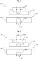
- Fig. 1 shows a transport device, designated as a whole by 25, with a sector 28 of a stator arrangement 26 and a magnetically levitable transport unit 1, in particular mover 27.
- the magnetically levitable transport unit 1 has an inductively supplied electrical functional unit 2.
- the electrical functional unit 2 has a power receiving unit 5, wherein the power receiving unit 5 is designed as a receiving coil 7.
- the magnetically levitable transport unit 1 levitates over the sector 28 of the stator arrangement 26.
- the sector 28 of the stator arrangement 26 is formed with a transmitting coil 29, via which an inductive coupling between the magnetically levitable transport unit 1 and the sector 28 of the stator arrangement 26 can be formed.
- the transmitting coil 29 is designed on a feed unit 30 for impressing a frequency-stabilized and amplitude-constant current.
- Fig. 2 shows a further embodiment of a magnetically levitable transport device 1 with an additional resonant circuit 6 inductively coupled to the receiving coil 7 of the transport unit 1.
- Components and functional units that are functionally and/or structurally similar or identical to the previous embodiment are designated with the same reference numerals and are not described separately again.
- An electrical consumer 3 which in this embodiment is a drive unit 8, in particular an electric motor 9, is connected to the receiving coil 7 of the magnetically levitable transport unit 1.
- the electrical Functional unit 2 of the magnetically levitable transport unit 1 has a power receiving unit 5 with an inductively coupled oscillating circuit 6 and an electrical consumer 3.
- a resonant inductive coupling between the transport unit 1 and the stator arrangement 26 is thus realized via the resonant circuit 6 coupled to the receiving coil 7.
- the drive unit 8 is thus supplied from the sector 28 of the stator arrangement 26 via the receiving coil 7 of the transport unit 1.
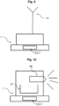
- Fig. 3 shows another embodiment of the magnetically levitable transport unit 1 according to Fig. 2 , wherein the electric drive unit 8 and the power receiving unit 5, which is further designed as a receiving coil 7, are shown as abstractly simplified two-dimensional models.
- Fig. 4 shows a further embodiment of the magnetically levitable transport unit 1, wherein the electrical functional unit 2 in this embodiment has, in addition to the receiving coil 7, an electrical storage unit 4 which can be charged via the energetic or inductive coupling.
- the electrical functional unit 2 of the magnetically levitable transport unit 1 has a power receiving unit 5 and an electrical storage unit 4.
- the embodiment according to Fig. 5 differs from the previous embodiments at least in that the electric motor 9 is coupled to the electrical storage unit 4.
- the electrical storage unit 4 of the transport unit 1 is formed with a sensor 36 which detects a state, in particular a charge state, of the electrical storage unit 4.
- the magnetically levitable transport unit 1 has an inductively supplied electrical functional unit 2, wherein the electrical functional unit 2 has an electrical consumer 3 and an electrical storage unit 4 and a power receiving unit 5.
- Fig. 6 shows the entire transport device 25 with the magnetically levitable transport unit 1 after Fig. 5 Sector 28 of the stator arrangement is according to Fig. 1 and Fig. 2 with the transmitting coil 29 and connected to a feed unit 30.
- the transmitting coil 29 generates an electromagnetic (alternating) field, whereby the electrical energy is transmitted from the transmitting coil 29 to the receiving coil 7 between the transmitting coil 29 and the receiving coil 7 of the transport unit due to a mutual induction.
- the transmitted electrical energy is used to charge the electrical storage unit 4 and to drive the electrical drive unit 8 or the electric motor 9.
- FIG. 7 to Fig. 16 show various embodiments with electrical functional units 2 formed on the magnetically levitable transport unit 1, which by means of the energetic coupling between the transmitting coil 29 of the sector 28 of the stator arrangement 26 and the receiving coil 7 of the transport unit 1.
- electrical functional units 2 formed on the magnetically levitable transport unit 1, which by means of the energetic coupling between the transmitting coil 29 of the sector 28 of the stator arrangement 26 and the receiving coil 7 of the transport unit 1.
- Functionally and/or structurally similar or identical components and functional units are provided with the same reference numerals and are not described separately again.
- Fig. 7 shows an embodiment of the magnetically levitable transport unit 1, wherein the transport unit 1 is designed with a motor-driven part 10, which via the energetic coupling between the receiving coil 7 and the transmitting coil 29, which are in the Fig. 1, 2 , 6 shown.
- the motor-driven part 10 is a robot 11 with a gripping element 12.
- Fig. 8 shows a further embodiment of the magnetically levitable transport unit 1 with a motor-driven part 10, which is designed as a drivable lifting device 18 with a movable container holder 13.
- the movement of the lifting device 18 and the container holder 13 is also generated via the energetic coupling.
- a vertical movement 44 and/or a horizontal movement 45 is possible.
- Fig. 9 shows a further embodiment of the magnetically levitable transport unit 1, which is designed with a particle counter 14.
- Fig. 10 differs from the Fig. 7 to 9 in that the transport unit 1 carries a storage container 37 and a dispensing unit 38.
- Fig. 11 shows a further embodiment of the magnetically levitable transport unit 1 with a decontamination system 15 formed on the transport unit 1.
- the decontamination system 15 is supplied with energy according to the previous embodiments.
- Fig. 12 shows, in contrast to the previous embodiments, a movable crimping device 17 with a crimping disk 16 formed on the transport unit 1.
- the crimping device 17 is driven via the energetic coupling, whereby rotational movements 46, vertical movements 44 and/or horizontal movements 45 of the crimping device 17 and/or the crimping disk 16 can be realized.
- Fig. 13 shows a further embodiment of the magnetically levitable transport unit 1, which is designed with a drivable lifting device 18, with a container holder 13 and a container 21 positioned on the container holder 13.
- the lifting device 18 is designed to use the energy of the energetic coupling to move a plug 19 via a vertical movement 44, whereby the container 21 is closed again.
- Fig. 14 shows a further embodiment with two laterally and vertically offset magnetically conductive transport units 1.
- a transport unit 1 carries the lifting device 18 with container 21 to Fig. 13
- the container holder 13 is additionally designed with a scale 39.
- a temperature control device 40 is formed around the container 21.
- a further transport unit 1 carries a motor-driven part 10, which in this embodiment is also designed as a robot 11 with a gripping element 12.
- a syringe 20 is gripped via the gripping element 12, which is then lifted by the lifting device 18 to fill the Container 21 is filled with a liquid 48, which was previously filled into the syringe 20 via a filling needle 47.
- the liquid 48, which is then located in the container 21, is kept at a defined temperature via the temperature control device 40, wherein a weight of the container 21 is determined before and/or after and/or during filling using the scale 39.
- Fig. 15 shows a further embodiment of the magnetically levitable transport unit 1 with a receptacle 22 for a nutrient medium carrier 23, in which a nutrient medium 24 is presented.
- Fig. 16 shows a further embodiment of the magnetically levitable transport unit 1 with robot 11, which carries the nutrient medium carrier 23 in which the nutrient medium 24 is presented.
- Fig. 17 shows the magnetically levitable transport unit 1 from Fig. 1 , wherein the transport unit 1 and the receiving coil 7 are surrounded by a sealed housing 41 and thus protected from contamination.
- Fig. 18 shows an embodiment of an arrangement of the transport device 25.
- the stator arrangement 26 has three sectors 28, each sector 28 being formed in sections, in this embodiment on the left side of each sector 28, with a transmitting coil 29, the transmitting coils 29 in turn forming the energy transmission areas 49.
- the energetic coupling is thus designed to maintain a continuous energy supply to the transport unit 1 in the left-hand energy transmission areas 49.
- all sectors 28 of the stator arrangement 26 are formed with a transmitting coil 29 and the transport unit 1 is supplied in sections in the respective energy transmission areas 49 via all sectors 28 of the stator arrangement 26.
- the two transport units 1 that are magnetically levitating and movable over the sectors 28 are each designed with a receiving coil 7. Since all sectors 28 of the stator arrangement are designed with a transmitting coil 23 and each transport unit 1 is designed with a receiving coil 7, a simultaneous supply of the transport unit 1 to a movement of the transport unit 1 is ensured via the continuous energetic coupling.
- Fig. 19 shows a further embodiment of an arrangement of the transport device 25 with eight sectors 28 of the stator arrangement 26 and four transport units 1 in a top view.
- the transmission coils 29 and thus also the energy transmission areas 49 are formed partly in sections over several sectors 28 and partly completely on one sector 28 of the stator arrangement 26.
- Fig. 20 shows an embodiment of a production plant 31 with a further embodiment of a transport device 25, wherein the transport unit 1, which is designed according to the previous embodiments with the receiving coil 7, is arranged in a controlled space 32.
- the controlled space 32 is formed by an isolator 33 or a RABS 34.
- the stator arrangement 26 is formed with three sectors 28, each sector 28 having a transmitting coil 28, via which the energetic coupling with the transport unit 1, according to the preceding embodiments.
- the transmitting coils 29 and thus also the energy transfer areas 49 are formed only in sections on two sectors 28 and completely over the entire area on one sector 28.
- the transport unit 1 is charged over the entire area of the sector 28, while the transport unit 1 on the other two sectors 28, on which the transmitting coil 29 is formed only in sections, is only charged when the transport unit 1 with the receiving coil 7 is located above it.
- a process unit 35 is shown schematically, which extends partially into the controlled space 32.
- the energetic coupling takes place at a distance from the process unit 35 and not directly at the process unit 35.
- the embodiment according to Fig. 21 differs from the previous embodiment in that not only the transport unit 1, but the entire transport device 25 and the process units 35 are within the controlled space 25, but encapsulated and/or spatially separated.
- Fig. 22 shows a further embodiment of a production plant 31 with a controlled room 32 and 8 sectors 28. Due to the design of the transmitting coils 29 of the sectors 28 or due to the energy transfer areas 49, the energetic coupling takes place at the process units 35 and at a distance from the process units 35.
- Fig. 23 shows another embodiment of a Production plant 31 after Fig. 20 , wherein the transport unit 1 is additionally supplied with energy via galvanic contacts at a charging station 42.
- Fig. 24 shows another embodiment of a production plant 31 according to Fig. 23 , with the essential difference that the sectors 28 of the stator arrangement 26 are arranged on a vertical plane 43.
- Fig. 25 shows a further embodiment of a production plant 31, which in this embodiment is designed as an aseptic fill-finish production plant 50 with a total of three process units 35 for carrying out an aseptic fill-finish process within a RABS 34 (cf. Fig. 20 ) or insulator 33 with an inlet 51 and an outlet 52.
- a RABS 34 cf. Fig. 20
- insulator 33 with an inlet 51 and an outlet 52.
- the number of process units can be variable in further embodiments not shown.
- the transmitting coils 29 are formed over a total of five sectors 28, for example, with the resulting energy transmission areas 49 directly adjacent to the process units 35. In further embodiments, the number of sectors 28 is also variable.
- the electrical functional unit 2 which is placed on the transport unit 1 and in the Figures 13 and 14
- the drivable lifting device 18 is provided with a container holder 13 and a container 21 placed in the container holder 13.
- the lifting device 18 is driven via the energetic coupling to the energy transfer areas 49.
- the container is first filled at the filling station 53 according to Fig. 14 filled with a pharmaceutical product.
- the filling can be differentiated from the embodiment according to Fig. 14 take place.
- the container holder 18 moves the syringe 20 or another container 21 provided by the process unit 35, for example, via a vertical movement 44, for example analogous to the embodiment according to Fig. 13 to.
- a closure lid or other closure element can then be placed on an opening of the container 21 at the closure station 54.
- Some closure means are then additionally provided with a cap and are crimped by a crimping device 17 or a crimping disk 16 (shown in Fig. 12 ) and the container 21 is thus closed.
- the container 21 is closed by further closure devices.
- the container is transported from the transport unit to an inspection station 55.
- it is checked whether the container 21 is completely and aseptically closed and can therefore be removed via the outlet 52.
- Fig. 26 shows a further embodiment of a production plant 31 with a further embodiment of a transport device 25 according to Fig. 20 , wherein two magnetically levitable transport units 1 are shown.
- the left magnetically levitable transport unit 1 is provided with a drivable lifting device 18 with a container holder 13 and a container 21 positioned on the container holder 13.
- the lifting device is designed to carry out a vertical movement 44.
- the transport unit shown in the embodiment on the right is in accordance with Fig. 7 with a motor-driven part 10.
- the container can be transferred from the left transport unit 1 to the right transport unit 1. It can thus be said that the energy transfer is used to actuate an electrical functional unit 2 for transferring a container 21 from one transport unit 1 to another transport unit 1.
- a transport device 25 consisting of a magnetically levitable transport unit 1 and a stator arrangement 26 formed with at least one sector 28, it is proposed that an energetic, preferably inductive coupling takes place between a receiving coil 7 formed on the transport unit 1 and a transmitting coil 29 of a sector of the stator arrangement 26 for continuous or discontinuous energy supply or energy transmission, preferably within a controlled space 32.
Landscapes
- Engineering & Computer Science (AREA)
- Power Engineering (AREA)
- Transportation (AREA)
- Mechanical Engineering (AREA)
- Computer Networks & Wireless Communication (AREA)
- Physics & Mathematics (AREA)
- Electromagnetism (AREA)
- Non-Mechanical Conveyors (AREA)
Priority Applications (1)
| Application Number | Priority Date | Filing Date | Title |
|---|---|---|---|
| EP23176671.8A EP4470818A1 (fr) | 2023-06-01 | 2023-06-01 | Unité de transport à lévitation magnétique, dispositif de transport avec un ensemble stator et au moins une unité de transport à lévitation magnétique, installation de production et procédé de couplage énergétique d'une unité de transport |
Applications Claiming Priority (1)
| Application Number | Priority Date | Filing Date | Title |
|---|---|---|---|
| EP23176671.8A EP4470818A1 (fr) | 2023-06-01 | 2023-06-01 | Unité de transport à lévitation magnétique, dispositif de transport avec un ensemble stator et au moins une unité de transport à lévitation magnétique, installation de production et procédé de couplage énergétique d'une unité de transport |
Publications (1)
| Publication Number | Publication Date |
|---|---|
| EP4470818A1 true EP4470818A1 (fr) | 2024-12-04 |
Family
ID=86657785
Family Applications (1)
| Application Number | Title | Priority Date | Filing Date |
|---|---|---|---|
| EP23176671.8A Pending EP4470818A1 (fr) | 2023-06-01 | 2023-06-01 | Unité de transport à lévitation magnétique, dispositif de transport avec un ensemble stator et au moins une unité de transport à lévitation magnétique, installation de production et procédé de couplage énergétique d'une unité de transport |
Country Status (1)
| Country | Link |
|---|---|
| EP (1) | EP4470818A1 (fr) |
Citations (4)
| Publication number | Priority date | Publication date | Assignee | Title |
|---|---|---|---|---|
| JP2014168372A (ja) * | 2013-01-31 | 2014-09-11 | Furukawa Electric Co Ltd:The | 磁気浮上式搬送装置及び荷台 |
| US20210099119A1 (en) * | 2019-09-30 | 2021-04-01 | Rockwell Automation Technologies, Inc. | System and Method for Wireless Power Transfer in a Linear Cart System |
| EP3960668A1 (fr) * | 2020-08-28 | 2022-03-02 | Schneider Electric Industries SAS | Système de moteur linéaire et procédé de fonctionnement d'un tel système |
| WO2022258566A1 (fr) * | 2021-06-08 | 2022-12-15 | B&R Industrial Automation GmbH | Procédé de transfert d'énergie par induction |
-
2023
- 2023-06-01 EP EP23176671.8A patent/EP4470818A1/fr active Pending
Patent Citations (4)
| Publication number | Priority date | Publication date | Assignee | Title |
|---|---|---|---|---|
| JP2014168372A (ja) * | 2013-01-31 | 2014-09-11 | Furukawa Electric Co Ltd:The | 磁気浮上式搬送装置及び荷台 |
| US20210099119A1 (en) * | 2019-09-30 | 2021-04-01 | Rockwell Automation Technologies, Inc. | System and Method for Wireless Power Transfer in a Linear Cart System |
| EP3960668A1 (fr) * | 2020-08-28 | 2022-03-02 | Schneider Electric Industries SAS | Système de moteur linéaire et procédé de fonctionnement d'un tel système |
| WO2022258566A1 (fr) * | 2021-06-08 | 2022-12-15 | B&R Industrial Automation GmbH | Procédé de transfert d'énergie par induction |
Similar Documents
| Publication | Publication Date | Title |
|---|---|---|
| EP3122682B1 (fr) | Procédé et système de contrôle de récipients remplis | |
| EP3590874A1 (fr) | Dispositif et procédé de transport de récipients à l'intérieur de machines isolantes | |
| EP3638616B1 (fr) | Machine de traitement des recipients avec robot mobil pour changer des composants | |
| EP3347301B1 (fr) | Dispositif et procede pour traiter des recipients avec engin volant pour surveillance | |
| EP3172819B1 (fr) | Dispositif de fermeture d'un contenant | |
| DE102013218402B4 (de) | Vorrichtung und Verfahren zum Durchführen von Sonderfunktionen einer Transporteinrichtung in einer Behälterbehandlungsanlage | |
| EP3807926A1 (fr) | Dispositif de transport pour le transport d'une plaquette | |
| DE102014214697A1 (de) | Vorrichtung zum Befüllen eines Behältnisses | |
| EP3715047A2 (fr) | Système pour usiner des pièces | |
| DE102014214696A1 (de) | Vorrichtung zum Transport eines Behältnisses relativ zu einer Füllstation | |
| EP3597549A1 (fr) | Machine de traitement de récipients à carrousel et moteur linéaire | |
| IES20170185A2 (en) | An autonomous sampling system | |
| EP3172820A1 (fr) | Dispositif pour peser un contenant | |
| DE102015209613A1 (de) | Transportvorrichtung | |
| EP3960668A1 (fr) | Système de moteur linéaire et procédé de fonctionnement d'un tel système | |
| DE102020212223A1 (de) | Berührungslose Beförderungsvorrichtung | |
| EP4470818A1 (fr) | Unité de transport à lévitation magnétique, dispositif de transport avec un ensemble stator et au moins une unité de transport à lévitation magnétique, installation de production et procédé de couplage énergétique d'une unité de transport | |
| DE102019108860A1 (de) | Fördereinrichtung und Verfahren zum Transportieren eines Behälters | |
| EP3956249B1 (fr) | Dispositif de transport d'objets | |
| EP4696625A1 (fr) | Unité de transport pouvant être déplacée magnétiquement et pouvant être déplacée sans contact d'au moins un secteur d'une surface d'entraînement et d'au moins deux degrés de liberté sur ladite unité de transport magnétique | |
| DE102020127346A1 (de) | Vorrichtung und Verfahren zum Ermitteln einer Ventilstellung eines beweglichen Füllventils, insbesondere eines Füllventils in einer Abfüllanlage für Flüssigkeiten | |
| DE202015106572U1 (de) | Hub-Dreh-Achse mit Raumtrennung | |
| EP3553814A1 (fr) | Dispositif de positionnement, système de chargement et/ou de déchargement et procédé de fonctionnement d'un dispositif de positionnement | |
| DE19650843C2 (de) | Antriebs- und Steuerungssystem für Produktbestrahlungsanlagen | |
| EP4446255B1 (fr) | Convoyeur aérien pour assembler des articles en ordre de tri et procédé correspondant |
Legal Events
| Date | Code | Title | Description |
|---|---|---|---|
| PUAI | Public reference made under article 153(3) epc to a published international application that has entered the european phase |
Free format text: ORIGINAL CODE: 0009012 |
|
| STAA | Information on the status of an ep patent application or granted ep patent |
Free format text: STATUS: THE APPLICATION HAS BEEN PUBLISHED |
|
| AK | Designated contracting states |
Kind code of ref document: A1 Designated state(s): AL AT BE BG CH CY CZ DE DK EE ES FI FR GB GR HR HU IE IS IT LI LT LU LV MC ME MK MT NL NO PL PT RO RS SE SI SK SM TR |
|
| STAA | Information on the status of an ep patent application or granted ep patent |
Free format text: STATUS: REQUEST FOR EXAMINATION WAS MADE |
|
| 17P | Request for examination filed |
Effective date: 20250604 |
|
| RAP3 | Party data changed (applicant data changed or rights of an application transferred) |
Owner name: TT INNOVATION AG |