EP4470843A2 - Dispositif de réduction d'énergie lors d'une influence d'énergie en cas de collision sur un véhicule utilitaire - Google Patents
Dispositif de réduction d'énergie lors d'une influence d'énergie en cas de collision sur un véhicule utilitaire Download PDFInfo
- Publication number
- EP4470843A2 EP4470843A2 EP24206419.4A EP24206419A EP4470843A2 EP 4470843 A2 EP4470843 A2 EP 4470843A2 EP 24206419 A EP24206419 A EP 24206419A EP 4470843 A2 EP4470843 A2 EP 4470843A2
- Authority
- EP
- European Patent Office
- Prior art keywords
- receiving element
- frame longitudinal
- longitudinal members
- crash
- commercial vehicle
- Prior art date
- Legal status (The legal status is an assumption and is not a legal conclusion. Google has not performed a legal analysis and makes no representation as to the accuracy of the status listed.)
- Granted
Links
Images


Classifications
-
- B—PERFORMING OPERATIONS; TRANSPORTING
- B60—VEHICLES IN GENERAL
- B60R—VEHICLES, VEHICLE FITTINGS, OR VEHICLE PARTS, NOT OTHERWISE PROVIDED FOR
- B60R19/00—Wheel guards; Radiator guards, e.g. grilles; Obstruction removers; Fittings damping bouncing force in collisions
- B60R19/02—Bumpers, i.e. impact receiving or absorbing members for protecting vehicles or fending off blows from other vehicles or objects
- B60R19/04—Bumpers, i.e. impact receiving or absorbing members for protecting vehicles or fending off blows from other vehicles or objects formed from more than one section in a side-by-side arrangement
- B60R19/12—Bumpers, i.e. impact receiving or absorbing members for protecting vehicles or fending off blows from other vehicles or objects formed from more than one section in a side-by-side arrangement vertically spaced
-
- B—PERFORMING OPERATIONS; TRANSPORTING
- B60—VEHICLES IN GENERAL
- B60R—VEHICLES, VEHICLE FITTINGS, OR VEHICLE PARTS, NOT OTHERWISE PROVIDED FOR
- B60R19/00—Wheel guards; Radiator guards, e.g. grilles; Obstruction removers; Fittings damping bouncing force in collisions
- B60R19/02—Bumpers, i.e. impact receiving or absorbing members for protecting vehicles or fending off blows from other vehicles or objects
- B60R19/18—Bumpers, i.e. impact receiving or absorbing members for protecting vehicles or fending off blows from other vehicles or objects characterised by the cross-section; Means within the bumper to absorb impact
-
- B—PERFORMING OPERATIONS; TRANSPORTING
- B62—LAND VEHICLES FOR TRAVELLING OTHERWISE THAN ON RAILS
- B62D—MOTOR VEHICLES; TRAILERS
- B62D21/00—Understructures, i.e. chassis frame on which a vehicle body may be mounted
- B62D21/02—Understructures, i.e. chassis frame on which a vehicle body may be mounted comprising longitudinally or transversely arranged frame members
-
- B—PERFORMING OPERATIONS; TRANSPORTING
- B62—LAND VEHICLES FOR TRAVELLING OTHERWISE THAN ON RAILS
- B62D—MOTOR VEHICLES; TRAILERS
- B62D21/00—Understructures, i.e. chassis frame on which a vehicle body may be mounted
- B62D21/15—Understructures, i.e. chassis frame on which a vehicle body may be mounted having impact absorbing means, e.g. a frame designed to permanently or temporarily change shape or dimension upon impact with another body
-
- B—PERFORMING OPERATIONS; TRANSPORTING
- B60—VEHICLES IN GENERAL
- B60R—VEHICLES, VEHICLE FITTINGS, OR VEHICLE PARTS, NOT OTHERWISE PROVIDED FOR
- B60R19/00—Wheel guards; Radiator guards, e.g. grilles; Obstruction removers; Fittings damping bouncing force in collisions
- B60R19/02—Bumpers, i.e. impact receiving or absorbing members for protecting vehicles or fending off blows from other vehicles or objects
- B60R19/18—Bumpers, i.e. impact receiving or absorbing members for protecting vehicles or fending off blows from other vehicles or objects characterised by the cross-section; Means within the bumper to absorb impact
- B60R2019/1806—Structural beams therefor, e.g. shock-absorbing
- B60R2019/1813—Structural beams therefor, e.g. shock-absorbing made of metal
-
- B—PERFORMING OPERATIONS; TRANSPORTING
- B60—VEHICLES IN GENERAL
- B60Y—INDEXING SCHEME RELATING TO ASPECTS CROSS-CUTTING VEHICLE TECHNOLOGY
- B60Y2306/00—Other features of vehicle sub-units
- B60Y2306/01—Reducing damages in case of crash, e.g. by improving battery protection
Definitions
- the invention relates to a device for dissipating energy when a commercial vehicle is exposed to energy caused by a crash.
- the invention further relates to a commercial vehicle with such a device.
- underrun protection devices In order to prevent a passenger car (car) from being pushed under the commercial vehicle in the front area when it collides with a commercial vehicle, underrun protection devices are known which are arranged in the area of the bumper in such a way that the forces occurring in the event of a collision are transmitted to the vehicle frame without the car sliding under the commercial vehicle.
- the aforementioned front underrun protection device is intended to reduce the risk of injury to a car driver and to ensure safe guidance of the front axle of the truck even after a frontal collision.
- a maximum installation height of 400 mm above the road surface for the underrun protection is prescribed.
- the disclosure document is referred to as an example. DE 10 2004 026 280 A1 referred to.
- the driver's cab of a commercial vehicle should be designed in such a way that, in the event of a crash, the commercial vehicle collides with another vehicle driving ahead, the driver can survive the crash in the driver's cab as unscathed as possible, even if the driver's cab is damaged.
- HV high-voltage
- HV components arranged in the area of the supporting frame cannot be adequately protected by known underrun protection devices or the known approaches to energy dissipation in the event of a crash-related energy impact on a commercial vehicle in the event of a crash-related collision of the commercial vehicle with a vehicle driving ahead.
- a basic idea of the invention is to separately protect an area above the frame longitudinal members of the commercial vehicle in the event of a crash. While known underrun protection devices protect the area below the frame longitudinal members and special cab designs can protect the driver located there, the area between and directly above the frame longitudinal members is not sufficiently protected in the event of a crash, especially if the commercial vehicle crashes into a trailer driving ahead, the supporting frame and loading area of which usually have a height such that the trailer penetrates exactly into the area just above the frame longitudinal members in the event of a crash.
- a deformation device for this purpose which can be deformed in the event of a crash while reducing impact forces and which can be fastened to the vehicle frame, preferably to the frame longitudinal members, in such a way that the deformation device extends above and transversely to the frame longitudinal members when installed.
- a drive component or HV component which is arranged behind it in the area of and/or between the frame longitudinal members can be protected in the event of a crash.
- This is particularly This is advantageous for a high-voltage battery located there, as it can not only be damaged in the event of a crash, but also, in contrast to a combustion engine, has a much greater risk of catching fire explosively.
- a device for dissipating energy in the event of a crash-related energy impact on a commercial vehicle.
- the commercial vehicle comprises, in a manner known per se, a vehicle frame, also referred to as a ladder frame, having two frame longitudinal members which are connected to one another by cross members.
- the device for energy reduction comprises a deformation device which can be deformed in the event of a crash, reducing impact forces or impact energy.
- the deformation device is designed to absorb part of the impact energy and/or to reduce it in a targeted manner by deformation.
- the deformation device can have one or more crash struts, which will be described below.
- the device further comprises two receiving elements, hereinafter referred to as the first and second receiving elements, for fastening the deformation device to the two frame longitudinal members and for introducing part of the impact energy into the frame longitudinal members.
- the deformation device is connected to the first receiving element at a first end region and to the second receiving element at an opposite second end region.
- first receiving element and the second receiving element are designed such that the first receiving element and the second receiving element can be and/or are each attached to one of the frame longitudinal members in order to introduce a portion of the impact energy into the ladder frame.
- the receiving elements can be suitably designed in order to be able to be attached to a frame longitudinal member in a force-fitting, form-fitting and/or material-fitting manner with regard to the usual dimensions, surface shape and provided through holes of the frame longitudinal member in order to be able to introduce a portion of the impact energy into the frame longitudinal members.
- Particularly advantageous structural embodiments of this are described below, to which the invention is not intended to be limited, however.
- the deformation device and the first and second receiving elements are designed such that when the receiving elements are each attached to the frame longitudinal members are, the deformation device extends above and transversely to the frame longitudinal members, preferably to protect a high-voltage device arranged between the frame longitudinal members in the event of a crash-related collision of the commercial vehicle with a trailer driving ahead.
- the deformation device and the two receiving elements are designed such that the deformation device can be mounted on the frame longitudinal members by means of the receiving elements in such a way that the deformation device, when mounted on the frame longitudinal members, extends above and transversely to the frame longitudinal members.
- the deformation device In the mounted state, the deformation device is arranged in front of the receiving elements as viewed in the forward direction of travel.
- a region of 0 to 50 cm above the frame longitudinal members is particularly advantageous since this region corresponds to the penetration height of the trailer in the event of a crash-related collision of the commercial vehicle with a trailer driving ahead.
- the deformation device comprises at least one strut, hereinafter also referred to as a crash strut, which can be deformed in the event of a crash, reducing impact forces.
- a crash strut is advantageous in terms of the good deformation properties in the event of a crash and can be easily manufactured with the desired energy absorption properties.
- the at least one crash strut is arranged above and transversely to the frame longitudinal members in the assembled state of the deformation device.
- the at least one strut is curved, preferably in such a way that the at least one strut is curved away from the receiving elements.
- the strut when the deformation device is mounted, the strut is curved in the forward direction of travel and, viewed in the forward direction of travel, is arranged in front of the receiving elements.
- This curved design is particularly advantageous with regard to an improved protective effect and deformation properties of the at least one crash strut.
- the strut can be banana-shaped and/or arched.
- the strut is designed as a hollow profile.
- the strut can be tubular, e.g. as a polygonal tube. Hollow profiles offer the particular advantage of high strength combined with low weight and good deformation behavior in the event of a crash.
- the strut comprises one or more inner tubes and an outer tube.
- the inner tube can be made of a higher quality material than the outer tube.
- the inner tube can be made of a material that has a higher strength than the material of the outer tube.
- the at least one inner tube is made of a carbon fiber composite material, while the outer tube is made as a steel tube and/or cast component.
- the deformation device can have two struts arranged parallel one above the other. This can further improve the energy absorption properties of the deformation device in the event of a crash.
- the two struts are arranged vertically one above the other. Three or more struts can also be provided.
- a cable e.g. a steel cable
- the steel cable can be attached to the fastening elements (as described below), to the receiving elements and/or to the frame longitudinal members in order to be able to divert even more forces to these elements.
- the deformation device can comprise a coupling part that encompasses the two struts arranged parallel one above the other, keeps them at a distance and is preferably welded to them at its edges and via welding holes. This improves the stability of the struts arranged parallel one above the other.
- the coupling part can comprise two plate-shaped and clamp-shaped partial elements, which are each attached to the struts on opposite sides, viewed in the forward direction of travel.
- the deformation device can have two fastening elements, between which the at least one strut is arranged and fastened at each end.
- the fastening elements can be connected and/or connected to the receiving element in a force-fitting and/or form-fitting manner, for example in that the fastening elements are each inserted into a receiving opening of one of the receiving elements and can be connected and/or connected there in a force-fitting manner to the receiving element.
- the strut can be welded to the fastening elements. Providing the at least one strut and the fastening elements as separate components and subsequently welding them has manufacturing advantages.
- the deformation device can be designed as a one-piece component or one-piece assembly.
- the deformation device, comprising the at least one strut and the two fastening elements, can be manufactured as a cast part, for example.
- a preferred embodiment of the fastening elements provides that the fastening elements have a bent course.
- the bent course is such that when the receiving elements are each fastened to the frame longitudinal members, a first section of the fastening element fastened directly to the receiving element runs flush with the receiving element and parallel to the longitudinal direction of the frame longitudinal members and is followed by a second section of the fastening element to which the at least one strut is fastened and which is bent outwards in relation to the longitudinal direction of the frame longitudinal members.
- the second slightly bent sections are now pulled slightly towards the middle, i.e. towards the crash strut, by this impact force transmitted by the crash strut.
- these second sections are aligned with the frame longitudinal members and the kink disappears or at least becomes smaller. This enables greater crash stability and force introduction in the longitudinal direction of the frame longitudinal members.
- the receiving opening of the receiving elements can each have a separating joint between the receiving element and the fastening element, such that the fastening element can be inserted into the receiving opening via a fit up to a stop and can then be screwed and/or screwed via recesses aligned with one another on the receiving element and the inserted area of the fastening element.
- a separating joint with a stop enables not only a simple Assembly also provides an additional form fit between the receiving elements and the fastening element.
- first receiving element and the second receiving element are designed such that the first receiving element can be and/or is attached to an upper side of one of the frame longitudinal members and the second receiving element is attached to an upper side of the other frame longitudinal member. This enables a structurally compact design of the device in order to enable the deformation device to be arranged above the frame longitudinal members.
- the receiving elements are each designed as wedge-shaped hollow profiles, comprising two side surfaces that converge at an acute angle, one of which is designed to be able to be attached to the top of one of the frame longitudinal members, and wherein the deformation device is attached to the side of the wedge-shaped hollow profiles facing away from the wedge tip.
- the side surface that is attached to the top of one of the frame longitudinal members can have essentially the same width as the top of the frame longitudinal member and have several through openings that can be arranged in alignment with holes in the hole structure on the top of the frame longitudinal members.
- a commercial vehicle preferably a truck, comprising two chassis longitudinal members connected to each other by cross members and further comprising a device for energy dissipation as described in this document.
- the commercial vehicle can thus have a device for dissipating energy in the event of a crash-related energy impact on the commercial vehicle.
- the device comprises a deformation device which can be deformed in the event of a crash to reduce impact forces, and a first receiving element and a second receiving element for fastening the deformation device to the two frame longitudinal members of the commercial vehicle.
- the deformation device is connected to the first receiving element at a first end region and to the second receiving element at an opposite second end region.
- the first receiving element is fastened to one of the frame longitudinal members, preferably on its upper side
- the second receiving element is attached to the other frame longitudinal member, preferably on its upper side.
- the deformation device extends above and transversely to the frame longitudinal members.
- a fastening plate can be provided which is screwed both to a side surface of the frame longitudinal member and to a vertical side wall of the receiving element. This increases the stability of the device fastened to the frame longitudinal members in a horizontal direction transverse to the longitudinal axis of the frame longitudinal members.
- a clamp-shaped fastening element hereinafter referred to as a form-locking element, can be provided, which clamp-shapedly encompasses an upper end region of the frame longitudinal member as well as a lower end region of the receiving element resting thereon to form a form-locking connection and is then screwed to the upper end region of the frame longitudinal member as well as to the end region of the receiving element resting thereon.
- a form-locking element With such a form-locking element, the stability of the device attached to the frame longitudinal members can be further increased.
- the commercial vehicle is an at least partially battery-electrically operated commercial vehicle, having at least one high-voltage (HV) component of a battery-electric drive of the commercial vehicle, which is arranged between the frame longitudinal members and below a lounge area of the driver's cab.
- the at least one HV component can be a battery pack or an inverter.
- the deformation device is arranged below a lounge area of the driver's cab and, viewed in the forward direction of travel, in front of the at least one high-voltage component to protect the at least one high-voltage component in the event of a crash-related collision of the commercial vehicle with a trailer driving ahead.
- the device described above also has the advantage that the device as a component can have the same so-called package across different vehicle models or series.
- the device is designed in such a way that it can be made up of several parts for assembly and disassembly and also offers a positive connection when assembled.
- the positive connection ensures that the crash strut does not collapse under the given load cases and that the permissible limit values for the component are within an acceptable level.
- Figure 1 shows a perspective view of a device 6 for energy dissipation according to an embodiment of the invention.
- FIG 1 Two frame longitudinal members 3 of a support frame or ladder frame 2 of a truck are shown, which are designed in a manner known per se.
- the frame longitudinal members 3 are designed as an open profile, here for example a U-profile.
- the section of the frame longitudinal members 3 shown is the front end region 3b of the frame longitudinal members 3, as seen in the forward direction of travel x.
- the truck can be designed as a battery-electrically powered truck (lorry).
- a battery pack and/or other HV components of the electric drive can be arranged between the frame longitudinal members 3 and in an area below a lounge area of the driver's cab, ie in a front area of the truck. This is shown in the Figure 2
- the battery pack is attached to the ladder frame 2 for fastening (not shown).
- a deformation device 10 is arranged and fastened to the frame longitudinal members 3 in such a way that the deformation device 10 extends in a front end region of the frame longitudinal members 3 above and transversely, i.e. in the Y direction, to the frame longitudinal members.
- the deformation device 10 is designed, e.g. based on experimental tests such as crash tests, so that it can be deformed in the event of a crash, reducing impact forces or impact energy.
- the deformation device is designed to absorb part of the impact energy and/or to reduce it in a targeted manner by deforming it, so that the truck is braked without the components of the deformation device 10 deforming the components behind it or causing excessive damage.
- the deformation device can have one or more crash struts 11.
- the deformation device 10 comprises two crash struts 11a and 11b arranged parallel one above the other.
- the crash struts 11a, 11b can be deformed under the influence of the impact force F with at least partial reduction of impact forces.
- the struts 11a, 11b are curved in the forward direction x, i.e. against the direction of the impact force.
- the struts 11a, 11b are designed as a hollow profile, in this case as a polygonal tube, which has an inner tube 14 and an outer tube 13.
- the crash energy is then partially dissipated by deformation of the crash struts 11a, 11b via a targeted deformation of the pipe system 11a, 11b, partially transferred to the vehicle in front and partially introduced into the approaching truck to a tolerable extent.
- the deformation device 10 has a fastening element 15 at each of its lateral end regions 10a, 10b, so that the two crash struts 11a, 11b can be fixed between the outer
- Fastening elements 15 are arranged and fastened to them at the ends.
- the fastening elements 15 comprise two sections 16 and 17.
- a first section 16 for fastening to a receiving element 20 fastened to the frame longitudinal member 3 and a second section 17 for holding the crash struts 11a, 11b.
- the second section has, purely as an example, two fastening plates arranged offset in the y-direction, each of which has a receiving opening adapted to the outer circumference of the crash struts 11a, 11b, in which the crash struts are received.
- the crash struts 11a, 11b are welded to the second section 17 via the contact edges.
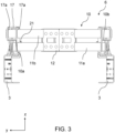
- the fastening elements 15 have a bent course, which can be seen in the top view of the Figure 2 is clearly visible.
- the bent course is characterized by the fact that the first section 16 of the fastening element 15, which is fastened directly to the receiving element 20, runs flush with the receiving element 20 and parallel to the longitudinal direction x of the frame longitudinal members 3, and the adjoining second section 17 of the fastening element 15 is bent outwards with respect to the longitudinal direction of the frame longitudinal members 3, so that a kink 16a is formed. If an impact force F acts on the crash struts 11a, 11b in the event of a crash, they are pulled in the direction of F and deformed. The second slightly bent sections 17 are now pulled somewhat towards the middle, i.e.
- a coupling part 12 which encompasses the two struts 11a, 11b arranged parallel one above the other in a central area, keeps them at a distance and is welded to them at its edges and via welding holes.
- the coupling part 12 has two plate-shaped and clamp-shaped sub-elements, each of which is attached to the struts 11a, 11b on opposite sides, as seen in the direction of travel.
- the sub-elements have welding holes so that they can be welded to the struts 11a and 11b via these and at their edges.
- a web section of the coupling part 12 extends between the struts 11a, 11b in the x direction, the height of which corresponds to the distance between the struts 11a, 11b in the z direction in order to keep the struts 11a, 11b at a distance.
- the deformation device 10 is attached to the frame longitudinal members 3 via two lateral mounts, referred to here as mount elements 20. Each of the mount elements 20 is attached to one of the frame longitudinal members 3.
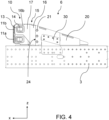
- the receiving elements 20 are each designed as wedge-shaped hollow profiles, comprising two side surfaces 25, 26 converging at an acute angle, of which the lower side surface rests on an upper side 3a of one of the frame longitudinal members 3 and is screwed to it.
- the screw connection 22 in the z-direction between the upper side 3a of the frame longitudinal members and the lower side surface 26 of the receiving elements 20 is in Figure 2 shown.
- a clamp-shaped form-locking element 40 is shown, which clamp-like surrounds an upper end region of the frame longitudinal member 3 as well as a lower end region of the receiving element 20 resting thereon to form a form-locking connection.
- the form-locking element is therefore attached in the y-direction and then screwed to the upper end region of the frame longitudinal member 3 as well as to the end region of the receiving element 20 resting thereon.
- the fastening elements 15 are each inserted into a receiving opening 24 of one of the receiving elements 15 and screwed there to the receiving element 15.
- the receiving opening 24 is formed by the non-pointed end region of the wedge-shaped receiving elements 20.
- the fastening element 15 is inserted into the receiving opening 24 via a fit 19 up to a stop 18 and then screwed via recesses aligned with one another on the receiving element 20 and the inserted region of the fastening element 15.
- the reference number 21 identifies this screw connection.
- Such a separating joint 23 with stop 18 between the receiving element 20 and the fastening element 15 enables not only simple assembly but also an additional positive connection between the receiving elements and the fastening element.
- a fastening plate 30 with a hole structure is provided, which is screwed both to a side surface 3c of the frame longitudinal member 3 and to a vertical side wall 27 of the receiving element 20 (not shown).
- the deformation device 10 with the at least one crash strut 11, which is arranged in front of the high-voltage component 5 as seen in the forward direction of travel x, can protect the high-voltage component in the event of a crash-related collision of the commercial vehicle with another vehicle, in particular a trailer driving ahead.
Landscapes
- Engineering & Computer Science (AREA)
- Mechanical Engineering (AREA)
- Chemical & Material Sciences (AREA)
- Combustion & Propulsion (AREA)
- Transportation (AREA)
- Body Structure For Vehicles (AREA)
- Vibration Dampers (AREA)
Applications Claiming Priority (3)
| Application Number | Priority Date | Filing Date | Title |
|---|---|---|---|
| DE102020110189.9A DE102020110189A1 (de) | 2020-04-14 | 2020-04-14 | Vorrichtung zum Energieabbau bei einer crashbedingten Energieeinwirkung auf ein Nutzfahrzeug |
| PCT/EP2021/056774 WO2021209217A1 (fr) | 2020-04-14 | 2021-03-17 | Système de dégradation d'énergie en cas d'énergie agissant sur un véhicule utilitaire à la suite d'une collision |
| EP21713609.2A EP4136011B1 (fr) | 2020-04-14 | 2021-03-17 | Véhicule utilitaire avec un système de dégradation d'énergie en cas d'énergie agissant sur le véhicule à la suite d'une collision |
Related Parent Applications (2)
| Application Number | Title | Priority Date | Filing Date |
|---|---|---|---|
| EP21713609.2A Division-Into EP4136011B1 (fr) | 2020-04-14 | 2021-03-17 | Véhicule utilitaire avec un système de dégradation d'énergie en cas d'énergie agissant sur le véhicule à la suite d'une collision |
| EP21713609.2A Division EP4136011B1 (fr) | 2020-04-14 | 2021-03-17 | Véhicule utilitaire avec un système de dégradation d'énergie en cas d'énergie agissant sur le véhicule à la suite d'une collision |
Publications (4)
| Publication Number | Publication Date |
|---|---|
| EP4470843A2 true EP4470843A2 (fr) | 2024-12-04 |
| EP4470843A3 EP4470843A3 (fr) | 2025-03-12 |
| EP4470843A8 EP4470843A8 (fr) | 2025-10-15 |
| EP4470843B1 EP4470843B1 (fr) | 2026-07-29 |
Family
ID=75143610
Family Applications (2)
| Application Number | Title | Priority Date | Filing Date |
|---|---|---|---|
| EP24206419.4A Active EP4470843B1 (fr) | 2020-04-14 | 2021-03-17 | Dispositif de réduction d'énergie lors d'une influence d'énergie en cas de collision sur un véhicule utilitaire |
| EP21713609.2A Active EP4136011B1 (fr) | 2020-04-14 | 2021-03-17 | Véhicule utilitaire avec un système de dégradation d'énergie en cas d'énergie agissant sur le véhicule à la suite d'une collision |
Family Applications After (1)
| Application Number | Title | Priority Date | Filing Date |
|---|---|---|---|
| EP21713609.2A Active EP4136011B1 (fr) | 2020-04-14 | 2021-03-17 | Véhicule utilitaire avec un système de dégradation d'énergie en cas d'énergie agissant sur le véhicule à la suite d'une collision |
Country Status (4)
| Country | Link |
|---|---|
| EP (2) | EP4470843B1 (fr) |
| KR (1) | KR20230002595A (fr) |
| DE (1) | DE102020110189A1 (fr) |
| WO (1) | WO2021209217A1 (fr) |
Families Citing this family (1)
| Publication number | Priority date | Publication date | Assignee | Title |
|---|---|---|---|---|
| EP4420960B1 (fr) | 2023-02-22 | 2025-11-26 | Volvo Truck Corporation | Structure de déformation de véhicule |
Citations (1)
| Publication number | Priority date | Publication date | Assignee | Title |
|---|---|---|---|---|
| DE102004026280A1 (de) | 2004-05-28 | 2005-12-15 | Man Nutzfahrzeuge Ag | Stossfängereinheit für einen Frontbereich eines Kraftfahrzeugs |
Family Cites Families (12)
| Publication number | Priority date | Publication date | Assignee | Title |
|---|---|---|---|---|
| JPS55263B2 (fr) * | 1971-12-27 | 1980-01-07 | ||
| DE2918136C2 (de) | 1979-05-05 | 1981-06-04 | Volkswagenwerk Ag, 3180 Wolfsburg | Vorderwagen für ein Frontlenkerfahrzeug |
| DE10221346C1 (de) | 2002-05-14 | 2003-10-09 | Daimler Chrysler Ag | Anbindung für ein Fahrerhaus |
| DE10321574A1 (de) | 2003-05-14 | 2004-12-02 | Daimlerchrysler Ag | Führerhaus für Kraftfahrzeuge |
| DE10357930A1 (de) | 2003-12-11 | 2005-07-14 | Daimlerchrysler Ag | Fahrerhaus-Tragstruktur für ein Nutzfahrzeug mit einer Sicherheitszelle |
| DE102005018830B3 (de) | 2005-04-22 | 2006-08-03 | Daimlerchrysler Ag | Rahmenkonstruktion zur Aufnahme eines schwenkbar gelagerten Fahrerhauses eines Lastkraftwagens |
| DE102008003488A1 (de) | 2008-01-08 | 2008-07-17 | Daimler Ag | Rahmenkopf für einen Fahrzeugrahmen eines Lastkraftwagens |
| DE102008030450A1 (de) * | 2008-06-26 | 2009-12-31 | Man Nutzfahrzeuge Ag | Frontquerträger eines Nutzfahrzeugs |
| DE102016216317A1 (de) * | 2016-08-30 | 2018-03-01 | Bayerische Motoren Werke Aktiengesellschaft | Stoßfängerquerträger |
| JP2018187976A (ja) * | 2017-04-28 | 2018-11-29 | ダイムラー・アクチェンゲゼルシャフトDaimler AG | 電動車両 |
| FR3066737B1 (fr) * | 2017-05-29 | 2020-09-04 | Peugeot Citroen Automobiles Sa | Partie avant de la caisse d'un vehicule a renforts lateraux en cas de choc frontal contre un autre vehicule |
| DE102019113842A1 (de) * | 2018-05-25 | 2019-11-28 | Ford Global Technologies, Llc | Kühlergrillverstärkung |
-
2020
- 2020-04-14 DE DE102020110189.9A patent/DE102020110189A1/de active Pending
-
2021
- 2021-03-17 EP EP24206419.4A patent/EP4470843B1/fr active Active
- 2021-03-17 WO PCT/EP2021/056774 patent/WO2021209217A1/fr not_active Ceased
- 2021-03-17 EP EP21713609.2A patent/EP4136011B1/fr active Active
- 2021-03-17 KR KR1020227039045A patent/KR20230002595A/ko active Pending
Patent Citations (1)
| Publication number | Priority date | Publication date | Assignee | Title |
|---|---|---|---|---|
| DE102004026280A1 (de) | 2004-05-28 | 2005-12-15 | Man Nutzfahrzeuge Ag | Stossfängereinheit für einen Frontbereich eines Kraftfahrzeugs |
Also Published As
| Publication number | Publication date |
|---|---|
| EP4136011B1 (fr) | 2024-11-27 |
| KR20230002595A (ko) | 2023-01-05 |
| EP4470843A8 (fr) | 2025-10-15 |
| DE102020110189A1 (de) | 2021-10-14 |
| EP4470843A3 (fr) | 2025-03-12 |
| EP4470843B1 (fr) | 2026-07-29 |
| WO2021209217A1 (fr) | 2021-10-21 |
| EP4136011A1 (fr) | 2023-02-22 |
Similar Documents
| Publication | Publication Date | Title |
|---|---|---|
| EP1669248B1 (fr) | Agencement de pare-choc pour un véhicule automobile | |
| DE102005039489B4 (de) | Stoßfänger für ein Kraftfahrzeug | |
| EP0798197A1 (fr) | Partie modulaire avant de véhicule | |
| DE102021114673B4 (de) | Unterer querlenkermechanismus für einen aufprall mit geringer überdeckung | |
| EP1990251B1 (fr) | Dispositif d'absorption d'énergie pour véhicules à éléments multiples | |
| EP3947021B1 (fr) | Dispositif de déformation pour un véhicule automobile et véhicule automobile comprenant un dispositif de déformation | |
| WO2019134785A1 (fr) | Structure de carrosserie et carrosserie pour une voiture particulière | |
| DE102021115317A1 (de) | Radablenkeinrichtung für einen aufprall mit geringer überdeckung | |
| DE102021129280A1 (de) | Anhängerkupplungsanordnung für ein Kraftfahrzeug | |
| DE102008052007A1 (de) | Cockpitquerträger für ein Kraftfahrzeug | |
| DE10358492A1 (de) | Crashelement in Form eines Hohlprofils | |
| DE102014205223A1 (de) | Anordnung in einem Kraftfahrzeugvorderwagen zum Schutz einer Kühlerbaugruppe sowie Kühler-Lagerelement für eine solche Anordnung | |
| DE102021115320A1 (de) | Fahrzeugstruktur zum handhaben von seitenlasten bei frontaufprallereignissen | |
| EP4136011B1 (fr) | Véhicule utilitaire avec un système de dégradation d'énergie en cas d'énergie agissant sur le véhicule à la suite d'une collision | |
| DE102015103755B4 (de) | Stoßfängersystem für ein Kraftfahrzeug | |
| DE10028704A1 (de) | Kraftfahrzeug mit Aggregateabsenkung | |
| DE102004018052B4 (de) | Unterfahrschutz für ein Kraftfahrzeug | |
| DE60132988T2 (de) | Motorhaubenvorrichtung | |
| EP4163193B1 (fr) | Structure avant pour un véhicule automobile avec une structure de collision disposée derrière un module de refroidissement | |
| DE102016204724B3 (de) | Anordnung eines Unterfahrschutzes an einem Vorderwagen eines Kraftfahrzeuges | |
| DE19847984C2 (de) | Leiterrahmen | |
| DE102021127481A1 (de) | Kraftfahrzeug mit einer im Crashfall verschiebbaren Traktionsbatterie | |
| DE102014017442A1 (de) | Baukastensystem für eine Achsträgerstruktur eines Kraftwagens | |
| DE102021003569B4 (de) | Verbindungseinrichtung zum Verbinden eines Batteriegehäuses mit einem Heckwagen-Rohbau einer Kraftwagenkarosserie | |
| DE102024100370B3 (de) | Querträger für ein Stoßfängersystem eines Kraftfahrzeugs, Stoßfängersystem mit einem solchen Querträger sowie Kraftfahrzeug mit einem derartigen Stoßfängersystem |
Legal Events
| Date | Code | Title | Description |
|---|---|---|---|
| PUAI | Public reference made under article 153(3) epc to a published international application that has entered the european phase |
Free format text: ORIGINAL CODE: 0009012 |
|
| STAA | Information on the status of an ep patent application or granted ep patent |
Free format text: STATUS: THE APPLICATION HAS BEEN PUBLISHED |
|
| AC | Divisional application: reference to earlier application |
Ref document number: 4136011 Country of ref document: EP Kind code of ref document: P |
|
| AK | Designated contracting states |
Kind code of ref document: A2 Designated state(s): AL AT BE BG CH CY CZ DE DK EE ES FI FR GB GR HR HU IE IS IT LI LT LU LV MC MK MT NL NO PL PT RO RS SE SI SK SM TR |
|
| REG | Reference to a national code |
Free format text: PREVIOUS MAIN CLASS: B60R0019180000 Ref country code: DE Ref legal event code: R079 Ref document number: 502021010852 Country of ref document: DE Free format text: PREVIOUS MAIN CLASS: B60R0019180000 Ipc: B62D0021150000 |
|
| PUAL | Search report despatched |
Free format text: ORIGINAL CODE: 0009013 |
|
| AK | Designated contracting states |
Kind code of ref document: A3 Designated state(s): AL AT BE BG CH CY CZ DE DK EE ES FI FR GB GR HR HU IE IS IT LI LT LU LV MC MK MT NL NO PL PT RO RS SE SI SK SM TR |
|
| RIC1 | Information provided on ipc code assigned before grant |
Ipc: B60R 19/18 20060101ALI20250203BHEP Ipc: B60R 19/12 20060101ALI20250203BHEP Ipc: B62D 21/02 20060101ALI20250203BHEP Ipc: B62D 21/15 20060101AFI20250203BHEP |
|
| STAA | Information on the status of an ep patent application or granted ep patent |
Free format text: STATUS: REQUEST FOR EXAMINATION WAS MADE |
|
| 17P | Request for examination filed |
Effective date: 20250903 |
|
| GRAP | Despatch of communication of intention to grant a patent |
Free format text: ORIGINAL CODE: EPIDOSNIGR1 |
|
| STAA | Information on the status of an ep patent application or granted ep patent |
Free format text: STATUS: GRANT OF PATENT IS INTENDED |
|
| INTG | Intention to grant announced |
Effective date: 20260225 |
|
| GRAS | Grant fee paid |
Free format text: ORIGINAL CODE: EPIDOSNIGR3 |
|
| GRAA | (expected) grant |
Free format text: ORIGINAL CODE: 0009210 |
|
| STAA | Information on the status of an ep patent application or granted ep patent |
Free format text: STATUS: THE PATENT HAS BEEN GRANTED |
|
| AC | Divisional application: reference to earlier application |
Ref document number: 4136011 Country of ref document: EP Kind code of ref document: P |
|
| AK | Designated contracting states |
Kind code of ref document: B1 Designated state(s): AL AT BE BG CH CY CZ DE DK EE ES FI FR GB GR HR HU IE IS IT LI LT LU LV MC MK MT NL NO PL PT RO RS SE SI SK SM TR |
|
| REG | Reference to a national code |
Ref country code: CH Ref legal event code: F10 Free format text: ST27 STATUS EVENT CODE: U-0-0-F10-F00 (AS PROVIDED BY THE NATIONAL OFFICE) Effective date: 20260729 |