EP4470847A1 - Verfahren zum steuern eines bremspedalsystems eines fahrzeugs in einer fahrzeugaufprallsituation - Google Patents
Verfahren zum steuern eines bremspedalsystems eines fahrzeugs in einer fahrzeugaufprallsituation Download PDFInfo
- Publication number
- EP4470847A1 EP4470847A1 EP23176868.0A EP23176868A EP4470847A1 EP 4470847 A1 EP4470847 A1 EP 4470847A1 EP 23176868 A EP23176868 A EP 23176868A EP 4470847 A1 EP4470847 A1 EP 4470847A1
- Authority
- EP
- European Patent Office
- Prior art keywords
- pedal
- force
- modulation unit
- vehicle
- signal
- Prior art date
- Legal status (The legal status is an assumption and is not a legal conclusion. Google has not performed a legal analysis and makes no representation as to the accuracy of the status listed.)
- Withdrawn
Links
Images



Classifications
-
- B—PERFORMING OPERATIONS; TRANSPORTING
- B60—VEHICLES IN GENERAL
- B60T—VEHICLE BRAKE CONTROL SYSTEMS OR PARTS THEREOF; BRAKE CONTROL SYSTEMS OR PARTS THEREOF, IN GENERAL; ARRANGEMENT OF BRAKING ELEMENTS ON VEHICLES IN GENERAL; PORTABLE DEVICES FOR PREVENTING UNWANTED MOVEMENT OF VEHICLES; VEHICLE MODIFICATIONS TO FACILITATE COOLING OF BRAKES
- B60T8/00—Arrangements for adjusting wheel-braking force to meet varying vehicular or ground-surface conditions, e.g. limiting or varying distribution of braking force
- B60T8/32—Arrangements for adjusting wheel-braking force to meet varying vehicular or ground-surface conditions, e.g. limiting or varying distribution of braking force responsive to a speed condition, e.g. acceleration or deceleration
-
- B—PERFORMING OPERATIONS; TRANSPORTING
- B60—VEHICLES IN GENERAL
- B60R—VEHICLES, VEHICLE FITTINGS, OR VEHICLE PARTS, NOT OTHERWISE PROVIDED FOR
- B60R21/00—Arrangements or fittings on vehicles for protecting or preventing injuries to occupants or pedestrians in case of accidents or other traffic risks
- B60R21/02—Occupant safety arrangements or fittings, e.g. crash pads
- B60R21/09—Control elements or operating handles movable from an operative to an out-of-the way position, e.g. pedals, switch knobs, window cranks
-
- B—PERFORMING OPERATIONS; TRANSPORTING
- B60—VEHICLES IN GENERAL
- B60T—VEHICLE BRAKE CONTROL SYSTEMS OR PARTS THEREOF; BRAKE CONTROL SYSTEMS OR PARTS THEREOF, IN GENERAL; ARRANGEMENT OF BRAKING ELEMENTS ON VEHICLES IN GENERAL; PORTABLE DEVICES FOR PREVENTING UNWANTED MOVEMENT OF VEHICLES; VEHICLE MODIFICATIONS TO FACILITATE COOLING OF BRAKES
- B60T7/00—Brake-action initiating means
- B60T7/02—Brake-action initiating means for personal initiation
- B60T7/04—Brake-action initiating means for personal initiation foot actuated
- B60T7/042—Brake-action initiating means for personal initiation foot actuated by electrical means, e.g. using travel or force sensors
Definitions
- the present disclosure relates to a method configured for controlling a brake pedal system of a vehicle in a vehicle crash situation, a brake pedal system of a vehicle, a vehicle, comprising the brake pedal system, a data processing apparatus associated with the method and a computer program product associated with the method.
- modem vehicles comprise several systems to protect the passengers from injuries, such as airbag systems and release systems of a brake pedal system of the vehicle.
- airbag systems and release systems of a brake pedal system of the vehicle.
- release systems of the brake pedal system are very cost-intensive. This makes it difficult to provide such systems in low-priced vehicles.
- a method configured for controlling a brake pedal system of a vehicle in a vehicle crash situation, the brake pedal system comprising a pedal arm and a modulation unit, the method comprising:
- the force may be adapted such that the risk of an injury of the driver of the vehicle may be reduced as far as possible.
- the driver will press the pedal of the brake pedal system as much as possible to decelerate the vehicle and prevent a crash, in particular a front crash.
- the modulation unit of the brake pedal system will typically modulate the force applied from the modulation unit onto the pedal arm such that the force is increased. This means that the harder the driver presses the pedal of the pedal arm, the more force will be applied from the modulation unit against his leg.
- this pedal feeling is desired in normal driving situations to give feedback to the driver on how much braking force he is currently applying, in a crash situation, this pedal feeling may pose a risk of injury.
- the force applied from the modulation unit onto the pedal arm may reach up to 1.500 N or more.
- the pedal arm is very stiff and can only give little or no more way to the leg of the driver pressing the pedal. Therefore, the high force F from the modulation unit is transmitted onto the leg and the spine of the driver, thereby possibly injuring the driver.
- the method of this disclosure provides for providing a second signal indicative of the force to be applied from the modulation unit onto the pedal arm, wherein the second signal is based on the first signal.
- the force applied from the modulation unit onto the pedal arm is based on the detected vehicle crash situation and, in particular, not on the normal driving situation anymore, in which the force of the modulation unit is being increased with increased pressing of the pedal from the driver.
- the second signal may be configured for or associated with deactivating a previous mode of the modulation unit, which in particular may be associated with a correlation between the force applied from the modulation unit and a pedal position of the pedal arm, which may be influenced by the driver by pressing the pedal of the pedal arm.
- the second signal may be configured for or associated with a new mode of the modulation unit. In the new mode, the force may be chosen or adapted so as to limit the risk of injury of the driver.
- the method of the first aspect may in particular be a computer implemented method. This means that at least one, multiple or all of the steps of the method may be carried out by one or more computers or data processing apparatus.
- the one or more computers or data processing apparatus may be configured as or provided inside of one more control units of the vehicle. These control units may also be configured to carry out other control operations than described by the method according to the first aspect.
- the force indicated by the second signal may be reduced compared to a force applied from the modulation unit onto the pedal arm when the first signal is received.
- the force applied from the modulation unit may be reduced immediately after crash impact, in particular compared to the force at and/or before crash impact, thereby reducing the stiffness of the pedal arm and giving way to the leg of the driver.
- the driver can push the pedal arm further with less resistance from the pedal arm based on the force applied from the modulation unit, the possibly harming force transmitted onto the leg thereby being reduced.
- the force indicated by the second signal may be predetermined.
- the second signal may comprise the predetermined force.
- the force may be chosen such that the risk of injury is reduced as far as possible.
- the force is predetermined within a range of 50 N to 400 N, in particular within a range of 100 N to 300 N. This range has been found to be both, significantly reducing the injury risk and technically realizable given the short time frame in which the force must be reduced to have the injury risk reducing effect during the vehicle crash situation.
- the second signal is indicative at least of a force applied from a pedal feel simulator of the modulation unit onto the pedal arm.
- the modulation unit may comprise a pedal feel simulator, the force from which is applied onto the pedal arm, may be indicated by the second signal. This force, which may be part of the entire force of the modulation unit applied onto the pedal arm, may be reduced.
- the pedal feel simulator may in particular be used in brake pedal systems based on a brake-by-wire system.
- the pedal feel simulator may give an additional force coupling in between the pedal and the wheel brakes to simulate the brake pedal feel in traditional brake pedal systems without brake-by-wire system.
- the second signal may be indicative of at least of a force applied from a hydraulic brake arrangement of the modulation unit onto the pedal arm.
- the modulation unit may comprise a hydraulic brake arrangement, the force from which is applied onto the pedal arm, may be indicated by the second signal. This force, which may be part of the entire force of the modulation unit applied onto the pedal arm, may be reduced.
- the hydraulic brake arrangement may comprise an arrangement or network of fluid paths for a hydraulic fluid contained therein and one or more valves for controlling the flow direction and/or flow rate of the hydraulic fluid, in particular to different parts or systems of the vehicle, such as the wheel brakes of the vehicle.
- control of the at least one valve of the hydraulic brake arrangement may be associated with a redirection of hydraulic fluid inside the hydraulic brake arrangement.
- the hydraulic fluid may be redirected from the wheel brakes to one or more other portions of the hydraulic brake arrangement such that the force applied from the modulation unit onto the pedal arm is reduced.
- the method may further comprise reducing a force applied from the modulation unit onto the pedal arm by applying the force indicated by the second signal, by means of the modulation unit, onto the pedal arm.
- the method may further comprise detecting, by means of a crash sensor of the vehicle, the vehicle crash situation.
- a brake pedal system of a vehicle comprising a pedal arm and a modulation unit, and the brake pedal system being configured for carrying out the method according to the first aspect of this disclosure.
- the brake pedal system in particular the modulation unit, may comprise a corresponding control unit or data processing apparatus for carrying out the method according to the first aspect of this disclosure.
- the provided second signal may be received at the modulation unit and consequently, an operation corresponding to the second signal may be carried out, i.e., the force indicated by the second signal, may be applied by the modulation unit onto the pedal arm.
- the brake pedal system may further comprise a pedal connected to the pedal arm.
- the brake pedal system may comprise a rod element connected to the pedal arm.
- the modulation unit may be connected to the rod element.
- the modulation unit may be configured to apply the force from the modulation unit onto the pedal arm by means of the rod element. Accordingly, the force applied from the modulation unit onto the pedal arm may be directly applied onto the rod element, and therefrom be transmitted to the pedal arm, onto which it is indirectly applied from the modulation unit.
- a vehicle comprising the brake pedal system of the second aspect of this disclosure.
- a data processing apparatus comprising means for carrying out the method of the first aspect of this disclosure, as far as it relates to steps, which may be computer-implemented.
- a computer program product comprising instructions which, when the program is executed by a computer, cause the computer to carry out the method according to the first aspect of this disclosure, as far as it relates to steps, which may be computer-implemented.
- the computer program product may be a computer program as such, meaning a computer program consisting of or comprising a program code to be executed by the computer.
- the computer program product may be a product such as a data storage, on which the computer program is temporarily or permanently stored.
- steps as first, second, etc. as provided herein is merely intended to make the methods and their steps referenceable and distinguishable from one another. By no means does the designation of methods and steps constitute a limitation of the scope of this disclosure.
- a first or second step of the method do not need to be present yet alone be performed before the third step unless they are explicitly referred to as being required per se or before the third step.
- the presentation of steps in a certain order is merely intended to facilitate one example of this disclosure and by no means constitutes a limitation of the scope of this disclosure.
- the steps may be carried out in any feasible order.
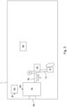
- FIG 1 schematically illustrates a vehicle 1 having a brake pedal system 10.
- the brake pedal system 10 comprises a pedal 12, which may have or consist of a pedal pad.
- the pedal 12 is designed for being pressed by means of a foot of a driver 2 of the vehicle 1.
- the brake pedal system 10 further comprises a pedal arm 14, which is connected or, in other words, attached to the pedal 12.
- the pedal arm 14 is rotatably suspended.
- the brake pedal system 10 further comprises a rod element 16 and a modulation unit 18 for modulating the braking force of the brake pedal system 10.
- the rod element 16 is connected to the pedal arm 14 and the modulation unit 18, thereby connecting the pedal arm 14 and the modulation unit 18 with each other.
- the driver 2 may press the pedal 12, thereby rotating the pedal arm 14 around the axis of rotation provided at its suspension, pushing the pedal 12 away from himself and pushing the rod element 16 inside the modulation unit 18.
- the pushing of the rod element 16 may be registered by a pedal feel simulator 18a, a hydraulic brake arrangement 18b and/or other means of the modulation unit 18.
- a hydraulic fluid of the hydraulic brake arrangement 18b may be pushed towards the wheel brakes (not depicted) of the vehicle 1, thereby pressing the wheel brakes.
- the modulation unit 18 by means of the pedal feel simulator 18a and/or the hydraulic brake arrangement 18b, for example, applies a force F against the pedal arm 14.
- the force F provided from the modulation unit 18 is opposed to the force applied by the driver 2 onto the pedal 12 when pressing the pedal 12.
- the force F provided by the modulation unit 18 thus creates a pedal feel, wherein the force F may become larger the more the pedal 12 is pressed.
- the force F is applied to the pedal arm 14 via the rod element 16, where the force from the modulation unit 18 is directly applied to and from there indirectly applied to, or, in other words, transmitted, via the rod element 16, to the pedal arm 14 and the pedal 12.
- the brake pedal system 10 While under normal operation, the brake pedal system 10 is working very well and intuitively for the driver 2 such that more pressure on the pedal 12 from the driver 2 correlates to more braking force on the wheel brakes, in a vehicle crash situation, the increasing or increased force F from the modulation unit 18 may be pose a risk of injury to the driver 2 and/or certain interior components of the vehicle 1, such as an airbag system, in particular a knee airbag system 20.
- Fig. 1 corresponds to a vehicle crash situation at crash impact.
- the vehicle crash situation occurs when the vehicle 1 crashes, which is indicated herein by a force arrow denominated C for crash.
- the crash C of this example is a frontal crash.
- a crash sensor 40 detects the vehicle crash situation.
- the crash sensor 40 may be pressure-sensitive, for example, and located at a front of the vehicle 1, for example. Other and/or alternative types of crash sensors 40 may as well be used to detect the vehicle crash situation.
- the driver 2 of that vehicle 1 will typically try to decelerate the vehicle 1 as much as possible and therefore press the pedal 12 of the brake pedal system 10 as strong as possible. Also, due to crash forces pushing the driver 2 towards the brake pedal system 10, the leg of the driver 2 may be further pressed onto the pedal 12. However, the modulation unit 18 will increase the force F with further travel of the pedal arm 14 associated with the pressing by the driver 2. The pedal arm 14 therefore becomes very stiff and there is no path for the leg of the driver 2 to travel any further when the vehicle 1 crashes. This poses a severe risk of injury for the driver 2, specifically his leg and spine.
- the driver 2 may have pressed the pedal 12 of the brake pedal system 10, thereby trying to brake the vehicle 1 as much as possible. Also, after impact, the pressing of the pedal 12 may even be greater, as explained above. This may result in a force F applied from the modulation unit 18 onto the pedal 12 of up to 3.000 N, which is further transmitted to the leg of the driver 2.
- the force F is reduced by the modulation unit 18 after detection of the vehicle crash situation as shown in Fig. 2 , which corresponds to a time of the vehicle crash situation, where airbags 22, 32 are being deployed or have been deployed, e.g., 5 ms after impact.
- a knee airbag 22 is being deployed from a knee airbag system 20 or unit and a steering wheel airbag 32 is being deployed from a steering wheel system 30 or unit.
- the previously or after deployment of the airbags 22, 32 reached force F of up to 3.000 N, e.g., 10 ms after impact, may be reduced to a force F of merely 300 N or less, thereby significantly reducing the stiffness of the pedal arm 14 and allowing the leg of the driver 2 to travel further against the force F, reducing the risk that his leg gets injured.
- the vehicle 1 For the force F of the modulation unit 18 to be lowered, the vehicle 1 comprises a data processing apparatus 50.
- the data processing apparatus 50 may comprise a computer readable storage medium (not depicted), which may have a computer program stored thereon.
- the computer program When the computer program is executed by means of the data processing apparatus 50, the method 100 as shown in Fig. 4 may be executed.
- the vehicle 1 is subjected to the crash C, the crash sensor 40 sensing the impact of the crash C, which corresponds to the situation of Fig. 1 . Thereby, the vehicle crash situation is detected.
- the crash sensor 40 in the first step 102 directly or, via another unit, sends a first signal S1 to the data processing apparatus 50, as shown in Fig. 1 .
- the first signal S1 is indicative of the detection of the vehicle crash situation.
- the first signal S1 is received by the data processing apparatus 50 in a second step 104 of the method 100.
- the data processing apparatus 50 may be a control unit of the vehicle 1 or the brake pedal system 10, for example.
- a second signal S2 indicative of a force F to be applied from the modulation unit 18 onto the rod element 16 and thereby onto the pedal arm 14 is provided.
- This provision of the second signal S2 may, in particular, be a generation of the second signal S2 and/or providing for, in particular sending to, the modulation unit 18 or a control unit thereof or of the brake pedal system 10.
- Both signals S1 and S2 may be in the form of information, such as a notice of a vehicle crash situation and the force F to be applied from the modulation unit 18 onto the pedal arm 14, and/or in the form of control instructions, e.g., the first signal S1 instructing the providing of the second signal S2 and the second signal S2 providing specific control measures for the modulation unit 18 on how to achieve the force F.
- a fourth step 108 the force F according to the second signal S2 is being applied by the modulation unit 18 onto the rod element 16 and therethrough onto the pedal arm 14 and the pedal 12.
- the force F after crash impact e.g., after 5 or 10 ms or in Fig. 2
- the force F is reduced compared to a force F that was applied at crash impact, e.g., at 0 ms or in Fig. 1 , where the vehicle crash situation was just noticed but no measure has been yet taken to reduce the force F.
- the force F may be predetermined by the second signal S2.
- the data processing apparatus 50 may predetermine the force F to be in the range of 50 N to 600 N, in particular 300 N or less, for example, as noted above.
- the second signal S2 may be associated with a control of one or more valves (not depicted) in the hydraulic brake arrangement 18b.
- a hydraulic fluid, in particular hydraulic brake fluid, inside the hydraulic brake arrangement 18b may be redirected away from the wheel brakes of the vehicle 1 to at least one other portion of the hydraulic brake arrangement 18b by closing and opening corresponding valves inside the hydraulic brake arrangement 18b.
- Figure 3 shows the vehicle 1 in the vehicle crash situation of Fig. 2 but without the driver 2 pressing the pedal 12 of the brake pedal system 10.
- Fig. 3 may correspond to a later time in the vehicle crash situation, e.g., at 25 to 40 ms, for example.
- the method 100 has great advantages. Specifically, when the vehicle 1 comprises interior components close to the brake pedal system 10, such as the depicted knee airbag system 20, the method 100 may prevent such interior components from being damaged as a result of the crash C.
- the front of the vehicle 1 is compressed, thereby pushing the brake pedal system 10 towards the knee airbag system 20.
- the pedal arm 14 is stiff due to a high force F applied thereon by the modulation unit 18, the pedal arm 14 cannot give way or at least less way to the knee airbag system 20. Accordingly, the knee airbag system 20 may be damaged in the process due to the high force F being transmitted over to the knee airbag system 20.
- the knee airbag system 20 can be given more way by pressing the pedal arm 14 similar to when the leg of the driver 2 presses the pedal 12. Accordingly, depending on the severity of the vehicle crash situation, it is more likely that the knee airbag system 20 stays in contact, when the method 100 is being executed. This makes a repair of the crashed vehicle 1 more cost-effective.
Landscapes
- Engineering & Computer Science (AREA)
- Mechanical Engineering (AREA)
- Transportation (AREA)
- Regulating Braking Force (AREA)
Priority Applications (3)
| Application Number | Priority Date | Filing Date | Title |
|---|---|---|---|
| EP23176868.0A EP4470847A1 (de) | 2023-06-01 | 2023-06-01 | Verfahren zum steuern eines bremspedalsystems eines fahrzeugs in einer fahrzeugaufprallsituation |
| EP24730244.1A EP4719836A1 (de) | 2023-06-01 | 2024-05-28 | Verfahren zum steuern eines bremspedalsystems eines fahrzeugs in einer fahrzeugaufprallsituation |
| PCT/EP2024/064609 WO2024246044A1 (en) | 2023-06-01 | 2024-05-28 | Method configured for controlling a brake pedal system of a vehicle in a vehicle crash situation |
Applications Claiming Priority (1)
| Application Number | Priority Date | Filing Date | Title |
|---|---|---|---|
| EP23176868.0A EP4470847A1 (de) | 2023-06-01 | 2023-06-01 | Verfahren zum steuern eines bremspedalsystems eines fahrzeugs in einer fahrzeugaufprallsituation |
Publications (1)
| Publication Number | Publication Date |
|---|---|
| EP4470847A1 true EP4470847A1 (de) | 2024-12-04 |
Family
ID=86656939
Family Applications (2)
| Application Number | Title | Priority Date | Filing Date |
|---|---|---|---|
| EP23176868.0A Withdrawn EP4470847A1 (de) | 2023-06-01 | 2023-06-01 | Verfahren zum steuern eines bremspedalsystems eines fahrzeugs in einer fahrzeugaufprallsituation |
| EP24730244.1A Pending EP4719836A1 (de) | 2023-06-01 | 2024-05-28 | Verfahren zum steuern eines bremspedalsystems eines fahrzeugs in einer fahrzeugaufprallsituation |
Family Applications After (1)
| Application Number | Title | Priority Date | Filing Date |
|---|---|---|---|
| EP24730244.1A Pending EP4719836A1 (de) | 2023-06-01 | 2024-05-28 | Verfahren zum steuern eines bremspedalsystems eines fahrzeugs in einer fahrzeugaufprallsituation |
Country Status (2)
| Country | Link |
|---|---|
| EP (2) | EP4470847A1 (de) |
| WO (1) | WO2024246044A1 (de) |
Citations (3)
| Publication number | Priority date | Publication date | Assignee | Title |
|---|---|---|---|---|
| WO2005021342A1 (en) * | 2003-08-28 | 2005-03-10 | Honda Motor Co., Ltd. | Brake pedal control apparatus |
| EP1749687A1 (de) * | 2005-08-04 | 2007-02-07 | Ford Global Technologies, LLC | Automatisches Kollisions-Management System |
| CN111169447A (zh) * | 2020-01-03 | 2020-05-19 | 大陆泰密克汽车系统(上海)有限公司 | 制动主缸总成、电子液压制动系统及机动车 |
-
2023
- 2023-06-01 EP EP23176868.0A patent/EP4470847A1/de not_active Withdrawn
-
2024
- 2024-05-28 WO PCT/EP2024/064609 patent/WO2024246044A1/en not_active Ceased
- 2024-05-28 EP EP24730244.1A patent/EP4719836A1/de active Pending
Patent Citations (3)
| Publication number | Priority date | Publication date | Assignee | Title |
|---|---|---|---|---|
| WO2005021342A1 (en) * | 2003-08-28 | 2005-03-10 | Honda Motor Co., Ltd. | Brake pedal control apparatus |
| EP1749687A1 (de) * | 2005-08-04 | 2007-02-07 | Ford Global Technologies, LLC | Automatisches Kollisions-Management System |
| CN111169447A (zh) * | 2020-01-03 | 2020-05-19 | 大陆泰密克汽车系统(上海)有限公司 | 制动主缸总成、电子液压制动系统及机动车 |
Also Published As
| Publication number | Publication date |
|---|---|
| EP4719836A1 (de) | 2026-04-08 |
| WO2024246044A1 (en) | 2024-12-05 |
Similar Documents
| Publication | Publication Date | Title |
|---|---|---|
| EP3000674B1 (de) | Elektronisches bremsunterstützungssystem zur verwendung bei fehlerhaftem oder abgenutztem betriebsbremssystem | |
| US8019509B2 (en) | Method and device for actuating a vehicle occupant protection means | |
| KR20180039690A (ko) | 브레이크 시스템 및 브레이크 시스템을 작동시키기 위한 방법 | |
| US20160362095A1 (en) | By-wire fallback braking mode for brake-by-wire systems in vehicles | |
| US12325391B2 (en) | Device and method for controlling a braking system, braking system and vehicle | |
| US20080058162A1 (en) | Method for operating a brake system of a motor vehicle | |
| KR20230108297A (ko) | 차량의 제동 시스템의 작동 방법, 제동 시스템을 위한 제어 장치, 제동 시스템 | |
| JP2022549928A (ja) | 単軌道の原動機付車両のための間隔制御機能または速度制御機能を実行する方法および装置 | |
| CN115805928A (zh) | 向机动车驾驶员通知与机动车制动系统关联的故障的方法 | |
| CN110641435A (zh) | 车辆制动方法及装置 | |
| EP1388456A1 (de) | Eine über das Gaspedal ausgelöste Notbremseinrichtung | |
| EP4719836A1 (de) | Verfahren zum steuern eines bremspedalsystems eines fahrzeugs in einer fahrzeugaufprallsituation | |
| US20060232124A1 (en) | Device and method for braking a vehicle | |
| US7954590B2 (en) | Method for a preventive-action protection system in a motor vehicle | |
| US6659572B2 (en) | System for exerting an amplified braking force | |
| CN110654342A (zh) | 用于触发车辆中的乘员保护机构的方法 | |
| CN103818370B (zh) | 紧急智能制动助力器及紧急制动方法 | |
| JPH06107141A (ja) | 車両の自動制動装置 | |
| JP7503204B2 (ja) | 車両を固定する方法 | |
| US20180118175A1 (en) | Pressure relief designs for vehicle braking system to prevent injuries | |
| CN117162993A (zh) | 一种电动汽车制动方法、系统及电动汽车 | |
| JP7791820B2 (ja) | 折り畳み可能な作動ペダルを有する車両用ブレーキシステム及び衝撃時のブレーキシステムの作動方法 | |
| JP2001515819A (ja) | 自動車のブレーキシステム駆動装置および方法 | |
| EP1694545B1 (de) | Verfahren und vorrichtung zur regelung eines kraftfahrzeuges mit einer elektrisch geregelten bremsanlage mit fahrdynamikregelung | |
| CN115675448A (zh) | 制动控制装置 |
Legal Events
| Date | Code | Title | Description |
|---|---|---|---|
| PUAI | Public reference made under article 153(3) epc to a published international application that has entered the european phase |
Free format text: ORIGINAL CODE: 0009012 |
|
| STAA | Information on the status of an ep patent application or granted ep patent |
Free format text: STATUS: REQUEST FOR EXAMINATION WAS MADE |
|
| STAA | Information on the status of an ep patent application or granted ep patent |
Free format text: STATUS: EXAMINATION IS IN PROGRESS |
|
| 17P | Request for examination filed |
Effective date: 20240116 |
|
| AK | Designated contracting states |
Kind code of ref document: A1 Designated state(s): AL AT BE BG CH CY CZ DE DK EE ES FI FR GB GR HR HU IE IS IT LI LT LU LV MC ME MK MT NL NO PL PT RO RS SE SI SK SM TR |
|
| 17Q | First examination report despatched |
Effective date: 20241112 |
|
| STAA | Information on the status of an ep patent application or granted ep patent |
Free format text: STATUS: THE APPLICATION HAS BEEN WITHDRAWN |
|
| 18W | Application withdrawn |
Effective date: 20250516 |