EP4470852A1 - Adaptive geschwindigkeitsregelung auf basis von reibung - Google Patents
Adaptive geschwindigkeitsregelung auf basis von reibung Download PDFInfo
- Publication number
- EP4470852A1 EP4470852A1 EP23176038.0A EP23176038A EP4470852A1 EP 4470852 A1 EP4470852 A1 EP 4470852A1 EP 23176038 A EP23176038 A EP 23176038A EP 4470852 A1 EP4470852 A1 EP 4470852A1
- Authority
- EP
- European Patent Office
- Prior art keywords
- vehicle
- distance
- braking
- brakes
- brake actuation
- Prior art date
- Legal status (The legal status is an assumption and is not a legal conclusion. Google has not performed a legal analysis and makes no representation as to the accuracy of the status listed.)
- Pending
Links
Images



Classifications
-
- B—PERFORMING OPERATIONS; TRANSPORTING
- B60—VEHICLES IN GENERAL
- B60T—VEHICLE BRAKE CONTROL SYSTEMS OR PARTS THEREOF; BRAKE CONTROL SYSTEMS OR PARTS THEREOF, IN GENERAL; ARRANGEMENT OF BRAKING ELEMENTS ON VEHICLES IN GENERAL; PORTABLE DEVICES FOR PREVENTING UNWANTED MOVEMENT OF VEHICLES; VEHICLE MODIFICATIONS TO FACILITATE COOLING OF BRAKES
- B60T7/00—Brake-action initiating means
- B60T7/12—Brake-action initiating means for automatic initiation; for initiation not subject to will of driver or passenger
- B60T7/22—Brake-action initiating means for automatic initiation; for initiation not subject to will of driver or passenger initiated by contact of vehicle, e.g. bumper, with an external object, e.g. another vehicle, or by means of contactless obstacle detectors mounted on the vehicle
-
- B—PERFORMING OPERATIONS; TRANSPORTING
- B60—VEHICLES IN GENERAL
- B60T—VEHICLE BRAKE CONTROL SYSTEMS OR PARTS THEREOF; BRAKE CONTROL SYSTEMS OR PARTS THEREOF, IN GENERAL; ARRANGEMENT OF BRAKING ELEMENTS ON VEHICLES IN GENERAL; PORTABLE DEVICES FOR PREVENTING UNWANTED MOVEMENT OF VEHICLES; VEHICLE MODIFICATIONS TO FACILITATE COOLING OF BRAKES
- B60T2201/00—Particular use of vehicle brake systems; Special systems using also the brakes; Special software modules within the brake system controller
- B60T2201/02—Active or adaptive cruise control system; Distance control
- B60T2201/022—Collision avoidance systems
-
- B—PERFORMING OPERATIONS; TRANSPORTING
- B60—VEHICLES IN GENERAL
- B60T—VEHICLE BRAKE CONTROL SYSTEMS OR PARTS THEREOF; BRAKE CONTROL SYSTEMS OR PARTS THEREOF, IN GENERAL; ARRANGEMENT OF BRAKING ELEMENTS ON VEHICLES IN GENERAL; PORTABLE DEVICES FOR PREVENTING UNWANTED MOVEMENT OF VEHICLES; VEHICLE MODIFICATIONS TO FACILITATE COOLING OF BRAKES
- B60T2210/00—Detection or estimation of road or environment conditions; Detection or estimation of road shapes
- B60T2210/10—Detection or estimation of road conditions
- B60T2210/12—Friction
-
- B—PERFORMING OPERATIONS; TRANSPORTING
- B60—VEHICLES IN GENERAL
- B60T—VEHICLE BRAKE CONTROL SYSTEMS OR PARTS THEREOF; BRAKE CONTROL SYSTEMS OR PARTS THEREOF, IN GENERAL; ARRANGEMENT OF BRAKING ELEMENTS ON VEHICLES IN GENERAL; PORTABLE DEVICES FOR PREVENTING UNWANTED MOVEMENT OF VEHICLES; VEHICLE MODIFICATIONS TO FACILITATE COOLING OF BRAKES
- B60T2270/00—Further aspects of brake control systems not otherwise provided for
- B60T2270/60—Regenerative braking
- B60T2270/604—Merging friction therewith; Adjusting their repartition
Definitions
- the present disclosure relates to a method for controlling operation of a vehicle.
- the disclosure relates to adaptive cruise control.
- the disclosure also relates to corresponding control arrangement and computer program, and to a vehicle comprising the control arrangement.
- Adaptive Cruise Control (ACC) systems use an on-board sensors to detect the distance between the host vehicle and a vehicle travelling ahead of the host, and the relative speed difference between the vehicles.
- the ACC automatically adjusts the speed of the host vehicle to keep it at a pre-set distance or time gap behind the vehicle travelling ahead.
- the adaptive cruise control system generates automatic interventions in the powertrain and/or braking systems of the host vehicle to slow the vehicle as necessary to maintain a target following distance.
- the target following distance is based on the pre-set following distance or time gap but may also be influenced by other factors such as power efficiency, road conditions and safety requirements.
- the disclosure relates a method for controlling operation of a vehicle comprising secondary brakes.
- the method comprises obtaining friction data indicative of friction between a road surface and a tire of the vehicle and determining, based on the obtained friction data and based on current operating conditions of the vehicle, braking capacity of the secondary brakes.
- the method further comprises controlling the vehicle to automatically actuate the secondary brakes, in response to the vehicle reaching a brake actuation distance to a vehicle travelling ahead, wherein the brake actuation distance is based on the estimated braking capacity of the secondary brakes.
- the brake actuation distance is long enough to ensure that a braking force required to maintain a safety distance to the vehicle travelling ahead, does not exceed the estimated braking capacity of the secondary brakes.
- the safety distance corresponds to a distance where primary brakes are automatically actuated. Hence, automatic actuation of primary brakes is avoided.
- required braking forces above a certain level are disregarded as a basis for the brake actuation distance.
- exceptional braking forces which are typically required very seldom, but in turn would require a very long brake actuation distance, can be disregarded.
- the brake actuation distance can be kept reasonably long.
- the certain level corresponds to a braking force applied by the vehicle, and/or a measured braking force applied by the vehicle travelling ahead, during a certain preceding time period.
- braking forces that have not been applied recently e.g., last 5-10 minutes
- the brake actuation distance is adjusted based on the friction data and/or road inclination. Hence, the brake actuation distance can be adjusted to consider road properties that may affect braking distance.
- the brake actuation distance is longer than a configured following distance upon the determined braking force falling below a predefined value.
- the secondary may be automatically actuated before the vehicle reaches a configured following distance set for example by a driver.
- the method comprises estimating a braking force required to maintain the safety distance to the vehicle travelling ahead based on operating conditions of the vehicle, and one or more of: physical properties, braking behaviour, driving speed and acceleration of the vehicle travelling ahead.
- the method comprises determining the brake actuation distance such that the estimated braking force matches the determined braking capacity of the secondary brakes. Thereby, the brake actuation distance may be set such that braking may be performed using only secondary brakes.
- the brake actuation distance depend on braking distance of the secondary brakes for the determined braking capacity and the current operating condition. Hence, the brake actuation distance depend on braking distance of secondary brakes under current road conditions, whereby the brake actuation distance is determined in an improved way.
- the obtaining friction data comprises one or more of: calculating the friction data based on sensor readings and vehicle properties, and receiving friction data from other vehicles, from road objects, or from a data storage.
- friction data may be obtained in various ways.
- the current operating conditions comprises one or more of road inclination, temperature, velocity, acceleration, historic or predicted braking behavior, map data, axle load, weather conditions and battery State of Charge, SoC.
- various parameters influencing braking capacity of secondary brakes may be considered in addition to the friction, whereby an improved determination of the braking capacity is obtained.
- the controlling comprises, performing particular measures, including increasing the minimum following distance, slowing down or limiting acceleration, upon the friction data indicating that the vehicle travelling ahead is driving on a road segment having friction below a certain threshold.
- additional measures may be taken when the road conditions are extremely poor Thereby, safety can be increased under exceptional road conditions.
- the controlling comprises activating an acceleration limitation of the vehicle upon the friction data indicating an upcoming road segment having friction below a certain threshold. Thereby, the driver may maintain better control of the vehicle, whereby the risk of accidents is reduced.
- the determining is based on braking capacity criteria defining braking capacity based on the obtained friction data and based on current operating conditions and/or wherein the brake actuation distance is determined based on one or more distance criteria.
- braking capacity criteria defining braking capacity based on the obtained friction data and based on current operating conditions and/or wherein the brake actuation distance is determined based on one or more distance criteria.
- the disclosure relates to a computer program comprising instructions which, when the computer program is executed by a computer, cause the computer to carry out the method according to the first aspect.
- the disclosure relates to a computer-readable medium comprising instructions which, when executed by a computer, cause the computer to carry out the method according to the first aspect.
- the disclosure relates to a control arrangement configured to perform the method according to the first aspect.
- Heavy vehicles such as trucks typically include a primary braking system, such as frictional brakes and one or more secondary braking systems separate from the primary braking system. Because the secondary brakes do generally not rely on friction it is typically preferable to use the secondary brakes, to avoid overheating and tear of the frictional brakes. In particular, it is beneficial to use regenerative brakes as they cause less power loss as the motion is converted to electrical energy that can be fed back to the battery.
- the proposed technique is based on the idea that road conditions, in particular friction, can be considered by the ACC in order to optimise braking, such that unnecessary use of primary brakes is avoided.
- the plurality of sensors 15 comprises vehicle sensors (such as LIDAR, RADAR and image sensors) for monitoring the surroundings of the vehicle 1.
- vehicle sensors such as LIDAR, RADAR and image sensors
- the output from the vehicle sensors 15 may provide input to the ACC or to an autonomous control system of the control arrangement 10, for use in autonomous driving.
- Fig. 2a illustrates distances considered by an adaptive cruise control system.
- a user enters a desired following distance d driver .
- the desired following distance d driver may be defined in meters (e.g. 10 meters) or in time (e.g. 3 seconds).
- the ACC then configures a target following distance d tar , which is a distance between the vehicle 1 and a vehicle travelling ahead 2 (herein also simply called the followed vehicle 2) that the ACC tries to maintain.
- the ACC will of course consider the desired following distance d driver when setting the target following distance d tar , but in some situations there may be a deviation between the desired following distance d driver and the target following distance d tar due to safety or energy consumption reasons.
- the ACC is configured to control the propulsion arrangement 11 and the brakes 12, 13 to keep the target following distance d tar as well as possible, while also considering driving comfort, tear, energy consumption and safety.
- the ACC system is configured to monitor a driving style of the followed vehicle 2 and to determine an expected value of deceleration of the followed vehicle 2.
- the estimated value of deceleration may consider various parameters such as speed of the followed vehicle 2, map data, vehicle type etc. In other words, the ACC typically attempts to drive as similar to a human being as possible.
- an ACC brakes the vehicle to maintain the target following distance d tar the secondary brakes are typically used as much as possible. However, if the vehicle 1 comes too close to the followed vehicle 2 the primary brakes 12 are also actuated.
- the distance where the primary brakes 12 are automatically actuated to avoid collision is herein referred to as a safety distance d WB .
- the ACC controls an amount of propelling torque applied until the vehicle 1 reaches, or is about to reach, the target following distance d tar .
- the vehicle At the target following distance d tar the vehicle is typically allowed to roll freely for a while, even if it exceeds the target following distance d tar , as unnecessary braking typically waste energy.
- the zone when neither torque nor braking force is applied is herein referred to as a power saving zone 4.
- a braking force is typically applied using secondary brakes in order to avoid using primary brakes.
- the distance where the secondary brakes 13 are automatically actuated to maintain the target following distance d tar is herein referred to as a brake actuation distance d AB .
- the secondary brakes 13 shall preferably be activated early enough to ensure that the vehicle 1 never reaches the safety distance d WB .
- How early the secondary brakes 13 have to be actuated depends on the braking capacity of the secondary brakes 13.
- the brake actuation distance d AB depends on how much braking torque the secondary brakes 13 can generate at a certain point in time.
- the brake actuation distance d AB may also be adjusted based on map data and friction.
- the inventors have realised that such an adjustment does not provide a balanced following distance in bad road conditions. The reason is that the need to take road conditions into account is tightly related to other factors such as driving environment and vehicle properties.
- Fig. 2b illustrates how the brake actuation distance d AB may be adjusted based on friction data on a slippery road.
- the brake actuation distance d AB is longer than the configured following distance d driver set by the driver. In some scenarios this may also affect the target following distance d tar , as it is typically desirable that the power saving zone 4 is not too short.
- both the brake actuation distance d AB and the target following distance d tar have been increased due to low friction. This means that on slippery roads (when the friction is below a certain limit) the vehicle 1 will start braking in advance, i.e. before it has reached the configured following distance d driver set by the driver.
- Fig. 3 illustrates a vehicle 1 obtaining friction data.
- Friction data may be obtained in various ways such as by calculating the friction data based on sensor readings and vehicle properties. For example, data from one or more of an image sensor, humidity sensor, rain sensor or temperature sensor may be used to estimate the friction coefficient according to commonly known methods. Alternatively, friction data may be received from other vehicles 2, from road objects, or from a data storage 5, such as a cloud server accessible by several vehicles. Hence, the vehicle 1 may be configured to communicate with such objects using Vehicle-to-Everything, V2X communication or using other communication technologies.
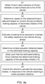
- Fig. 4a illustrates the proposed method for controlling operation of a vehicle 1 comprising secondary brakes 13.
- the secondary brakes 13 comprises regenerative brakes and/or auxiliary brakes.
- the method is for use in a control arrangement, such as the control arrangement 10 of the vehicle 1 ( Fig. 1 ).
- the method is typically performed during normal operation of the vehicle 1 ( Fig. 1 ), such as when an ACC is activated to control speed of the vehicle 1.
- the method may be performed to control operation of an autonomous vehicle.
- the method may be implemented as computer program comprising instructions which, when the program is executed by a computer (e.g., a processor in the control arrangement 10 ( Fig. 4 )), cause the computer to carry out the methods.
- a computer e.g., a processor in the control arrangement 10 ( Fig. 4 )
- the computer program is stored in a computer-readable medium (e.g., a memory or a compact disc) that comprises instructions which, when executed by a computer, cause the computer to carry out the method.
- the method comprises obtaining S1 friction data indicative of friction between a road surface 3 and a tire 14 of the vehicle.
- the friction data comprises a coefficient of friction of a road on which the vehicle is driving, or on which it is about to drive.
- the friction data may indicate current or expected friction.
- the method further comprises determining S2, based on the obtained friction data and based on current operating conditions of the vehicle 1, braking capacity of the secondary brakes 13.
- the maximum force that the secondary brakes 13 can apply may depend on temperature, velocity, tear, acceleration and for regenerative brakes also on battery State of Charge, SoC.
- the maximum force the tires can apply on the road may on the other hand depend on vehicle properties, such as tire characteristics, axle load, level of tear, humidity, tire pressure etc.
- vehicle properties such as tire characteristics, axle load, level of tear, humidity, tire pressure etc.
- the current operating conditions comprises one or more of tire characteristics, temperature, level of tear, humidity, pressure, axle load and battery State of Charge, SoC.
- the determining S2 is typically performed using a set of rules, such as a formula or model of the secondary brakes 13.
- the determining S2 is based on braking capacity criteria defining braking capacity based on the obtained friction data and based on current operating conditions.
- the brake actuation distance d AB is long enough to assure that the secondary brakes 13 will be able to keep the vehicle 1 at a distance that is longer than the safety distance d WB without using primary brakes 12.
- the brake actuation distance d AB will vary based on speed, inclination, friction, vehicle properties etc., as well as depending on driving conditions of the followed vehicle 2.
- the brake actuation distance d AB is long enough to ensure that a braking force required to maintain a safety distance d WB to the vehicle travelling ahead 2, does not exceed the estimated braking capacity of the secondary brakes 13. This means for example that the brake actuation distance is increased if a speed difference between the vehicle and the vehicle travelling ahead is significant as stronger braking is required.
- a braking force required to maintain a safety distance d WB where primary brakes 13 are automatically actuated does not exceed the capacity of the secondary brakes 13. This may be accomplished by evaluating driving pattern and predicting braking behaviour of the followed vehicle 2. For example, an expected value of braking of the followed vehicle 2 may be compared with a braking distance that the braking capacity results in under current driving conditions, such as weather conditions, velocity, acceleration, map data, etc. A braking force corresponding to the braking distance is then estimated.
- the method comprises estimating S3 a braking force required to maintain the safety distance d WB to the vehicle travelling ahead 2 based on operating conditions of the vehicle 1, and one or more of: physical properties, braking behaviour, driving speed and acceleration of the vehicle travelling ahead 2.
- the disclosure proposes that the brake actuation distance d AB is based on a variety of parameters, including estimated braking capacity.
- the method comprises the explicit step of determining S4 a brake actuation distance d AB based on the estimated braking capacity.
- a variety of parameters may be considered in the determination S4.
- the determining S4 is typically performed using a set of rules, such as a formula for calculating the brake actuation distance d AB .
- the brake actuation distance d AB is determined based on one or more distance criteria.
- the brake actuation distance d AB typically depend on the current braking distance that the determined braking capacity results in.
- the distance criteria may take a plurality of parameters as input. Even if the braking capacity is known, the braking distance depend on current driving conditions such as speed (in particular speed difference between the vehicle 1 and the vehicle travelling ahead 2), inclination etc. Hence, these parameters have to be taken into account when setting a brake actuation distance d AB .
- additional adjustments may be performed based on, for example, road conditions and inclination to provide a balance between power saving, safety, tear, noise, comfort, etc.
- the brake actuation distance d AB depend on braking distance of the secondary brakes 13 for the determined braking capacity and the current operating condition.
- the determining S4 comprises determining S4a the brake actuation distance d AB such that the estimated braking force matches the determined braking capacity of the secondary brakes 13.
- a brake actuation distance d AB is selected to ensure that the braking force required to maintain a safety distance does not exceed the capacity of the secondary brakes.
- the brake actuation distance d AB may be very long, which may be undesirable for other reasons. This may be resolved by simply disregarding unlikely braking in the estimation S3 of braking force required to maintain the safety distance d WB . One can simply risk that the primary brakes 12 will have to be actuated in the event of abrupt braking, as it is unlikely to happen. In other words, in some embodiments, required braking forces above a certain level are disregarded as a basis for the brake actuation distance.
- What braking should be disregarded may be determined based on driving history of the followed vehicle 2. For example, braking forces larger than braking forces applied in the last 10 minutes may be disregarded. This may of course depend on the type of driving and would change if the vehicle 1 enters another type of road (e.g., a road with another speed limitation) or if traffic conditions change.
- the certain level corresponds to a braking force applied by the vehicle 1, and/or a measured braking force applied by the vehicle travelling ahead 2, during a certain preceding time period.
- brake actuation distance d AB may in some situations be longer that the configured following distance d driver (See Fig. 2b ). Hence, the vehicle 1 may automatically start braking before it has reached the configured following distance d driver set by the driver. In other words, in some embodiments, the brake actuation distance d AB is longer than a configured following distance d driver , upon the determined braking force falling below a predefined value.
- the controlling S5 may also consider particular road conditions indicated by the friction data.
- Fig. 4b illustrates details of the particular embodiments of the controlling S5 in further detail. For example, it may be a driver preference to allow increase of the determined brake actuation distance d AB and/or target following distance d tar if it is extremely low friction. This can only be up to the furthest the radar can see or however far it is possible to detect vehicles with high reliability vehicle sensors. In some embodiments, this may involve a driver tip for manual driving or that the ACC disengages because it is such low friction that it must back beyond the brake actuation distance d AB . It shall be noted that the steps of Fig. 4b may be performed independently on the preceding steps S2-S4.
- the computer-readable medium may be a non-transitory computer-readable medium, such as a tangible electronic, magnetic, optical, infrared, electromagnetic, and/or semiconductor system, apparatus, and/or device.
- the computer-readable memory is for example one or more of the memories in the control arrangement 10.
- the proposed method may be implemented as a computer program.
- the computer program then comprises instructions which, when the computer program is executed by a computer, cause the computer to carry out the method according to any one of the aspects, embodiments or examples as described herein.
- control arrangement 10 is configured to obtain friction data indicative of friction between a road surface 3 and a tire 14 of the vehicle, and to determining, based on the obtained friction data and based on current operating conditions of the vehicle 1, braking capacity of the secondary brakes 13.
- the control arrangement 10 is also configured to control, the vehicle to automatically actuate the secondary brakes, in response to the vehicle reaching a brake actuation distance d AB to a vehicle travelling ahead 2, wherein the brake actuation distance d AB is based on the estimated braking capacity of the secondary brakes.
- control arrangement is configured to perform the method according to any one of the embodiments described in connection with Figs. 4a and 4b .
Landscapes
- Engineering & Computer Science (AREA)
- Transportation (AREA)
- Mechanical Engineering (AREA)
- Regulating Braking Force (AREA)
Priority Applications (3)
| Application Number | Priority Date | Filing Date | Title |
|---|---|---|---|
| EP23176038.0A EP4470852A1 (de) | 2023-05-30 | 2023-05-30 | Adaptive geschwindigkeitsregelung auf basis von reibung |
| PCT/SE2024/050498 WO2024248702A1 (en) | 2023-05-30 | 2024-05-22 | Adaptive cruise control based on friction |
| CN202480036108.8A CN121358643A (zh) | 2023-05-30 | 2024-05-22 | 基于摩擦的自适应巡航控制 |
Applications Claiming Priority (1)
| Application Number | Priority Date | Filing Date | Title |
|---|---|---|---|
| EP23176038.0A EP4470852A1 (de) | 2023-05-30 | 2023-05-30 | Adaptive geschwindigkeitsregelung auf basis von reibung |
Publications (1)
| Publication Number | Publication Date |
|---|---|
| EP4470852A1 true EP4470852A1 (de) | 2024-12-04 |
Family
ID=86688823
Family Applications (1)
| Application Number | Title | Priority Date | Filing Date |
|---|---|---|---|
| EP23176038.0A Pending EP4470852A1 (de) | 2023-05-30 | 2023-05-30 | Adaptive geschwindigkeitsregelung auf basis von reibung |
Country Status (3)
| Country | Link |
|---|---|
| EP (1) | EP4470852A1 (de) |
| CN (1) | CN121358643A (de) |
| WO (1) | WO2024248702A1 (de) |
Citations (4)
| Publication number | Priority date | Publication date | Assignee | Title |
|---|---|---|---|---|
| US20040085197A1 (en) * | 2000-11-24 | 2004-05-06 | Kazuya Watanabe | Vehicle collision preventing apparatus |
| US20130211644A1 (en) * | 2012-02-09 | 2013-08-15 | Hitachi Automotive Systems, Ltd. | Vehicle Motion Control Apparatus, and Vehicle Motion Control Method |
| US20150307099A1 (en) * | 2012-12-10 | 2015-10-29 | Jaguar Land Rover Limited | Vehicle and method of control thereof |
| US11590941B2 (en) * | 2019-12-20 | 2023-02-28 | Hl Klemove Corp. | Driver assistance apparatus and driver assistance method |
-
2023
- 2023-05-30 EP EP23176038.0A patent/EP4470852A1/de active Pending
-
2024
- 2024-05-22 WO PCT/SE2024/050498 patent/WO2024248702A1/en not_active Ceased
- 2024-05-22 CN CN202480036108.8A patent/CN121358643A/zh active Pending
Patent Citations (4)
| Publication number | Priority date | Publication date | Assignee | Title |
|---|---|---|---|---|
| US20040085197A1 (en) * | 2000-11-24 | 2004-05-06 | Kazuya Watanabe | Vehicle collision preventing apparatus |
| US20130211644A1 (en) * | 2012-02-09 | 2013-08-15 | Hitachi Automotive Systems, Ltd. | Vehicle Motion Control Apparatus, and Vehicle Motion Control Method |
| US20150307099A1 (en) * | 2012-12-10 | 2015-10-29 | Jaguar Land Rover Limited | Vehicle and method of control thereof |
| US11590941B2 (en) * | 2019-12-20 | 2023-02-28 | Hl Klemove Corp. | Driver assistance apparatus and driver assistance method |
Also Published As
| Publication number | Publication date |
|---|---|
| CN121358643A (zh) | 2026-01-16 |
| WO2024248702A1 (en) | 2024-12-05 |
Similar Documents
| Publication | Publication Date | Title |
|---|---|---|
| US11780437B2 (en) | Controlling movement of a vehicle | |
| US10363930B2 (en) | Method of speed control for a vehicle | |
| US9409554B2 (en) | Method for improving the driving stability | |
| US9676390B2 (en) | Vehicle traction control | |
| US9688279B2 (en) | Vehicle traction control method, system, controller and vehicle with such a system | |
| US9545926B2 (en) | Vehicle control system and method for switching between powertrain control functions | |
| EP2885182B1 (de) | Geschwindigkeitsregelungssystem und betriebsverfahren dafür | |
| GB2511831A (en) | System and method for selecting a driveline gear ratio | |
| KR20240093520A (ko) | 대형 차량을 위한 역 타이어 모델 부스트 기능 | |
| CN117460652A (zh) | 用于在上坡和/或下坡至少部分自动行驶期间控制车辆的制动力矩的方法、用于车辆的计算装置以及辅助系统 | |
| EP2885188B1 (de) | System und verfahren zur auswahl eines antriebsstrang-getriebe-verhältnisses | |
| EP4470852A1 (de) | Adaptive geschwindigkeitsregelung auf basis von reibung | |
| GB2618562A (en) | Control system for a vehicle and method | |
| US20240416917A1 (en) | Predictive overtaking support | |
| US12459493B2 (en) | System and method for brake assisted vehicle turning radius reduction | |
| US20250136076A1 (en) | Control arrangement and method for deactivating an adaptive cruise control system of a vehicle | |
| US20250326394A1 (en) | Speed control system for a vehicle and method | |
| SE2350643A1 (en) | Following distance based on historic brake events | |
| GB2629126A (en) | Control system for a vehicle and method | |
| GB2632059A (en) | Control system for a vehicle and method | |
| CN121001906A (zh) | 用于估计轮胎与路面之间的相互作用的方法及系统 |
Legal Events
| Date | Code | Title | Description |
|---|---|---|---|
| PUAI | Public reference made under article 153(3) epc to a published international application that has entered the european phase |
Free format text: ORIGINAL CODE: 0009012 |
|
| STAA | Information on the status of an ep patent application or granted ep patent |
Free format text: STATUS: THE APPLICATION HAS BEEN PUBLISHED |
|
| AK | Designated contracting states |
Kind code of ref document: A1 Designated state(s): AL AT BE BG CH CY CZ DE DK EE ES FI FR GB GR HR HU IE IS IT LI LT LU LV MC ME MK MT NL NO PL PT RO RS SE SI SK SM TR |
|
| STAA | Information on the status of an ep patent application or granted ep patent |
Free format text: STATUS: REQUEST FOR EXAMINATION WAS MADE |
|
| 17P | Request for examination filed |
Effective date: 20250604 |