EP4470892A1 - Dispositif de chauffage de poignée - Google Patents
Dispositif de chauffage de poignée Download PDFInfo
- Publication number
- EP4470892A1 EP4470892A1 EP24178812.4A EP24178812A EP4470892A1 EP 4470892 A1 EP4470892 A1 EP 4470892A1 EP 24178812 A EP24178812 A EP 24178812A EP 4470892 A1 EP4470892 A1 EP 4470892A1
- Authority
- EP
- European Patent Office
- Prior art keywords
- handle pipe
- grip
- handlebar
- handle
- heating device
- Prior art date
- Legal status (The legal status is an assumption and is not a legal conclusion. Google has not performed a legal analysis and makes no representation as to the accuracy of the status listed.)
- Pending
Links
Images






Classifications
-
- B—PERFORMING OPERATIONS; TRANSPORTING
- B62—LAND VEHICLES FOR TRAVELLING OTHERWISE THAN ON RAILS
- B62J—CYCLE SADDLES OR SEATS; AUXILIARY DEVICES OR ACCESSORIES SPECIALLY ADAPTED TO CYCLES AND NOT OTHERWISE PROVIDED FOR, e.g. ARTICLE CARRIERS OR CYCLE PROTECTORS
- B62J33/00—Arrangements for warming riders specially adapted for cycles
-
- B—PERFORMING OPERATIONS; TRANSPORTING
- B62—LAND VEHICLES FOR TRAVELLING OTHERWISE THAN ON RAILS
- B62K—CYCLES; CYCLE FRAMES; CYCLE STEERING DEVICES; RIDER-OPERATED TERMINAL CONTROLS SPECIALLY ADAPTED FOR CYCLES; CYCLE AXLE SUSPENSIONS; CYCLE SIDECARS, FORECARS, OR THE LIKE
- B62K21/00—Steering devices
- B62K21/26—Handlebar grips
-
- B—PERFORMING OPERATIONS; TRANSPORTING
- B62—LAND VEHICLES FOR TRAVELLING OTHERWISE THAN ON RAILS
- B62K—CYCLES; CYCLE FRAMES; CYCLE STEERING DEVICES; RIDER-OPERATED TERMINAL CONTROLS SPECIALLY ADAPTED FOR CYCLES; CYCLE AXLE SUSPENSIONS; CYCLE SIDECARS, FORECARS, OR THE LIKE
- B62K23/00—Rider-operated controls specially adapted for cycles, i.e. means for initiating control operations, e.g. levers, grips
- B62K23/02—Rider-operated controls specially adapted for cycles, i.e. means for initiating control operations, e.g. levers, grips hand actuated
- B62K23/04—Twist grips
Definitions
- the present invention relates to a grip heating device that warms a handle grip by causing a heating portion to generate heat.
- a handle grip that can be held by a driver is formed at the distal end of the handlebar.
- a handle grip includes a built-in heating portion (a plate-shaped heater or the like) through which the current can flow from a battery mounted on the vehicle.
- a grip heating device is disclosed in, for example, Japan Utility Model Publication JPH02-010190Y2 .
- the grip heating device in the related art described above since a concave portion is formed on the surface side in contact with the handlebar, it is possible to reduce the contact area with the handlebar and prevent the heat generated by the plate-shaped heater from being transmitted to the handlebar and lost.
- the concave portion may cause the backlash between the grip heating device and the handlebar, and the attachment state to the handlebar may become unstable.
- the object of the present invention is to provide a grip heating device capable of preventing the heat generated by a heating portion from being transmitted to a handlebar, and of stabilizing the attachment state to the handlebar.
- the handle pipe has the groove that forms the gap between the handle pipe and the handlebar, and the groove continuously extends between the one end and the other end of the handle pipe. Therefore, the heat generated in the heating portion can be prevented from being transmitted to the handlebar, and the attachment state to the handlebar can be stabilized.
- the groove is linearly formed from the one end to the other end of the handle pipe, and the plurality of grooves are formed at equal intervals in the circumferential direction. Therefore, the attachment state to the handlebar can be further stabilized while reducing the contact area with the handlebar.
- the handle pipe since the handle pipe is attached to the handlebar to be rotatable relative to the handlebar, the handle pipe can be applied to a throttle grip attached to the right side end portion of the handlebar of the vehicle, and a rotation operation for a throttle operation can be smoothly performed.
- the handle pipe since the handle pipe is attached to the handlebar to be fixed on the handlebar, the handle pipe can be applied to the holding grip attached to the left side end portion of the handlebar of the vehicle, and holding by the driver can be reliably and stably performed.
- a grip heating device is used for heating a handle grip (left and right holding grips held by a driver) attached to the distal end of a handlebar of a two-wheel vehicle.
- the grip heating device includes a right side grip heating device R attached to a right side end portion Ha of a handlebar H and a left side grip heating device L attached to a left side end portion Hb of the handlebar H.
- the right side grip heating device R is attached adjacent to a switch case C1 in which various switches are formed.
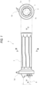
- the right side grip heating device R includes a handle pipe 1, a flexible substrate 2 serving as a heating portion, a handle grip 3, and a cover member 4.
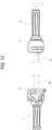
- the handle pipe 1 of the right side grip heating device R is attached to the right side end portion Ha of the handlebar H to be rotatable about the axis (the ⁇ direction shown in FIG. 12 ), and functions as a throttle grip that can control the driving source of the vehicle by the rotation operation.
- the handle pipe 1 is made of hard resin molded into the cylindrical shape, and is implemented such that the flexible substrate 2 is wound around the outer peripheral surface of the handle pipe 1. Further, the cover member 4 made of resin is attached to the base end side of the handle pipe 1, and wiring h1 is attached to the cover member 4.
- the flexible substrate 2 is formed of a sheet-shaped flexible member wound around the outer peripheral surface of the handle pipe 1, and has a heat generating region 2a in which a predetermined heating wire pattern is formed on the front surface or the back surface as shown in FIG. 7 .
- a plurality of position determination openings a are formed at predetermined positions on the surface of the flexible substrate 2, and the flexible substrate 2 can be positioned with respect to the handle pipe 1 by inserting the position determination openings a into position determination protrusions b formed on the outer peripheral surface of the handle pipe 1.
- the heating wire pattern formed on the flexible substrate 2 is connected to the wiring h1 extending from a power source (not shown) (for example, a battery mounted on the vehicle).
- a power source for example, a battery mounted on the vehicle.
- the current flows through the heating wire pattern to generate heat. Therefore, the heat is transmitted to the handle grip 3 to heat the holding surface formed on the outer peripheral surface of the handle grip 3.
- the handle grip 3 is formed on the outer periphery of the handle pipe 1 via the flexible substrate 2, can be held by the driver, and is made of a predetermined resin material (for example, a soft resin such as an elastomer or a rubber material). Specifically, the handle grip 3 including the flexible substrate 2 therein can be obtained by placing the handle pipe 1 around which the flexible substrate 2 is wound in a predetermined mold and secondarily molding the outer periphery of the handle pipe 1 with a predetermined resin material.
- a predetermined resin material for example, a soft resin such as an elastomer or a rubber material.
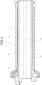
- the handle pipe 1 has a groove 1a that is formed on the inner peripheral surface thereof and that forms a gap K between the handle pipe 1 and the right side end portion Ha of the handlebar H.
- the groove 1a has a concave shape continuously extending between one end and the other end of the handle pipe 1 in the axial direction, and a plurality of grooves 1a are formed on the inner peripheral surface of the handle pipe 1 in the circumferential direction.
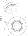
- the groove 1a formed in the handle pipe 1 of the right side grip heating device R is linearly formed from the one end (the distal end) to the other end (the base end) of the handle pipe 1 as shown in FIG. 2 , and a plurality of grooves 1a are formed at equal intervals on the inner peripheral surface in the circumferential direction as shown in FIG. 6 .
- the handle pipe 1 is rotatable relative to the handlebar H.
- the gap K is interposed between the handle pipe 1 and the handlebar H, the heat generated in the flexible substrate 2 can be prevented from being transmitted to the handlebar H, and the handle grip 3 can be efficiently heated.
- the handle pipe 1 of the right side grip heating device R rotates on the outer peripheral surface of the handlebar H when the throttle operation is performed. Therefore, the backlash during the rotation can be reduced by forming a plurality of grooves 1a at equal intervals in the circumferential direction.
- the left side grip heating device L is attached adjacent to a switch case C2 in which various switches are formed.
- the left side grip heating device L includes a handle pipe 5, a heating wire 6 serving as a heating portion, a handle grip 7, and an attachment plate 8.
- the handle pipe 5 of the left side grip heating device L is attached to the left side end portion Hb of the handlebar H to be fixed on the handlebar H with an adhesive or the like, and can be held by the driver.
- the handle pipe 5 is made of hard resin molded into the cylindrical shape, and the heating wire 6 is spirally wound around the outer peripheral surface of the handle pipe 5. Further, an attachment plate 8 made of resin is attached to the base end side of the handle pipe 5, and wiring h2 is attached to the attachment plate 8.
- the heating wire 6 is made of a conductive member spirally wound around the outer peripheral surface of the handle pipe 5, and is connected to the wiring h2 extending from a power source (not shown) (for example, a battery mounted on the vehicle).
- a power source for example, a battery mounted on the vehicle.
- the current is supplied from the power source, the current flows to generate heat. Therefore, the heat is transmitted to the handle grip 7 to warm the holding surface formed on the outer peripheral surface of the handle grip 7.
- the handle grip 7 is formed on the outer periphery of the handle pipe 5 via the heating wire 6, can be held by the driver, and is made of a predetermined resin material (for example, a soft resin such as an elastomer or a rubber material). Specifically, the handle grip 7 including the heating wire 6 therein can be obtained by placing the handle pipe 5 around which the heating wire 6 is wound in a predetermined mold and secondarily molding the outer periphery of the handle pipe 5 with a predetermined resin material.
- a predetermined resin material for example, a soft resin such as an elastomer or a rubber material.
- the handle pipe 5 has a groove 5a that is formed on the inner peripheral surface thereof and that forms the gap K between the handle pipe 5 and the left side end portion Hb of the handlebar H.
- the groove 5a has a concave shape continuously extending between one end and the other end of the handle pipe 5 in the axial direction, and a plurality of grooves 5a are formed on the inner peripheral surface of the handle pipe 5 in the circumferential direction.
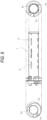
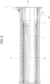
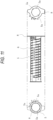
- the groove 5a formed in the handle pipe 5 of the left side grip heating device L is linearly formed from the one end (the distal end) to the other end (the base end) of the handle pipe 5 as shown in FIG. 9 , and a plurality of grooves 5a are formed on the inner peripheral surface in the circumferential direction as shown in FIGS. 8 and 11 .
- the left side grip heating device L is attached to the left side end portion Hb of the handlebar H, the handle pipe 5 is fixed relative to the handlebar H. Since the handle pipe 5 of the left side grip heating device L has an adhesive surface for the handlebar H on the inner peripheral surface of the handle pipe 5, the groove 5a is formed at a position avoiding the adhesive surface.
- the gap K is interposed between the handle pipe 5 and the handlebar H, the heat generated in the heating wire 6 can be prevented from being transmitted to the handlebar H, and the handle grip 7 can be efficiently heated.
- the handle pipe 5 of the left side grip heating device L is fixed on the handlebar H with an adhesive or the like, the handle pipe 5 can be reliably fixed while ensuring a constant contact area with the handlebar H.
- the right side grip heating device R (the example) according to the present embodiment and a comparative example in which the groove 1a is not formed but other configurations, dimensions, and the like are the same were prepared, and experiments were performed in a dark room and a place where the ambient temperature is 22°C.
- the handle pipe (1, 5) has the groove (1a, 5a) that forms the gap K between the handle pipe (1, 5) and the handlebar H, and the groove (1a, 5a) continuously extends between one end and the other end of the handle pipe (1, 5). Therefore, the heat generated in the flexible substrate 2 or the heating wire 6 can be prevented from being transmitted to the handlebar H, and the attachment state to the handlebar H can be stabilized.
- a plurality of grooves (1a, 5a) according to the present embodiment are formed on the inner peripheral surface of the handle pipe (1, 5) in the circumferential direction (over the entire circumference), it is possible to stabilize the attachment state to the handlebar H while reducing the contact area with the handlebar H.
- the groove 1a of the right side grip heating device R is linearly formed from one end to the other end of the handle pipe 1, and a plurality of grooves 1a are formed at equal intervals in the circumferential direction. Therefore, the attachment state to the handlebar H can be further stabilized while reducing the contact area with the handlebar H.
- the handle pipe 1 since the handle pipe 1 is attached to the handlebar H to be rotatable relative to the handlebar H, the handle pipe 1 can be applied to the throttle grip attached to the right side end portion Ha of the handlebar H of the vehicle, and the rotation operation for the throttle operation can be smoothly performed. Furthermore, according to the left side grip heating device L, since the handle pipe 5 is attached to the handlebar H to be fixed on the handlebar H, the handle pipe 5 can be applied to the holding grip attached to the left side end portion Hb of the handlebar H of the vehicle, and the holding of the driver can be reliably and stably performed.
- the present invention is not limited thereto, and for example, a heating portion of another form may be used instead of the flexible substrate 2 and the heating wire 6, and the handle grip (3, 7) may have another shape, material, or the like. It is sufficient that the groove (1a, 5a) continuously extends between one end and the other end of the handle pipe (1, 5) and forms the gap K between the handle pipe (1, 5) and the handlebar H, and the depth dimension and the width dimension of the groove may differ depending on the location.
- the present invention is applied to heating the handle grip (3, 7) of the two-wheel vehicle.
- the present invention may be applied to other vehicles (vehicles including a handlebar, such as an ATV and a snowmobile).
- the present invention can be applied to devices having a different external shape or having other functions added.
Landscapes
- Engineering & Computer Science (AREA)
- Mechanical Engineering (AREA)
- Steering Devices For Bicycles And Motorcycles (AREA)
Applications Claiming Priority (1)
| Application Number | Priority Date | Filing Date | Title |
|---|---|---|---|
| JP2023089822A JP2024172240A (ja) | 2023-05-31 | 2023-05-31 | グリップ加温装置 |
Publications (1)
| Publication Number | Publication Date |
|---|---|
| EP4470892A1 true EP4470892A1 (fr) | 2024-12-04 |
Family
ID=91331303
Family Applications (1)
| Application Number | Title | Priority Date | Filing Date |
|---|---|---|---|
| EP24178812.4A Pending EP4470892A1 (fr) | 2023-05-31 | 2024-05-29 | Dispositif de chauffage de poignée |
Country Status (2)
| Country | Link |
|---|---|
| EP (1) | EP4470892A1 (fr) |
| JP (1) | JP2024172240A (fr) |
Citations (5)
| Publication number | Priority date | Publication date | Assignee | Title |
|---|---|---|---|---|
| US4471209A (en) * | 1981-12-31 | 1984-09-11 | Hollander James M | Electrically heated hand grips for vehicle handle bars |
| JPH0210190Y2 (fr) | 1983-05-12 | 1990-03-14 | ||
| JP2002331980A (ja) * | 2001-05-11 | 2002-11-19 | Nissei Electric Co Ltd | ハンドルグリップヒータおよびその固定方法 |
| DE102005014682A1 (de) * | 2005-03-29 | 2006-10-19 | Thomas Brehmer | Handgriff mit Heizeinrichtung |
| JP2016113002A (ja) * | 2014-12-15 | 2016-06-23 | 株式会社日本ロック | ハンドルグリップ装置 |
-
2023
- 2023-05-31 JP JP2023089822A patent/JP2024172240A/ja active Pending
-
2024
- 2024-05-29 EP EP24178812.4A patent/EP4470892A1/fr active Pending
Patent Citations (5)
| Publication number | Priority date | Publication date | Assignee | Title |
|---|---|---|---|---|
| US4471209A (en) * | 1981-12-31 | 1984-09-11 | Hollander James M | Electrically heated hand grips for vehicle handle bars |
| JPH0210190Y2 (fr) | 1983-05-12 | 1990-03-14 | ||
| JP2002331980A (ja) * | 2001-05-11 | 2002-11-19 | Nissei Electric Co Ltd | ハンドルグリップヒータおよびその固定方法 |
| DE102005014682A1 (de) * | 2005-03-29 | 2006-10-19 | Thomas Brehmer | Handgriff mit Heizeinrichtung |
| JP2016113002A (ja) * | 2014-12-15 | 2016-06-23 | 株式会社日本ロック | ハンドルグリップ装置 |
Also Published As
| Publication number | Publication date |
|---|---|
| JP2024172240A (ja) | 2024-12-12 |
Similar Documents
| Publication | Publication Date | Title |
|---|---|---|
| US6114668A (en) | Heater-containing grip for vehicles | |
| KR100689915B1 (ko) | 회전식 가변 저항기 | |
| EP1714662B1 (fr) | Assemblage d'une fiche et un élément de chauffage pour une diffuseur de substances volatiles | |
| EP0687190A4 (fr) | Film d'actionnement a memoire de forme reparti dans l'espace | |
| JP4939025B2 (ja) | 電熱ヒータ付きハンドル用グリップ部材 | |
| US20060248683A1 (en) | Grip | |
| JP6691742B2 (ja) | グリップ加温装置 | |
| JP5898798B1 (ja) | ハンドルグリップ、およびハンドルグリップの内部筐体 | |
| JP2024172240A (ja) | グリップ加温装置 | |
| JP7529210B2 (ja) | スロットルグリップ加温装置 | |
| JP4213406B2 (ja) | グリップヒータの制御装置 | |
| JP2016113002A (ja) | ハンドルグリップ装置 | |
| JPH1081282A (ja) | 車両用ヒータ内蔵グリップ | |
| US2812412A (en) | Manually turnable wheels | |
| JP2015048069A (ja) | 自動二輪車用グリップヒーター装置 | |
| JPH085115Y2 (ja) | 二輪車等のハンドルのグリップヒーター装置 | |
| JP3966111B2 (ja) | ステアリングホイール | |
| JPH0355510Y2 (fr) | ||
| JP2008195312A (ja) | 電熱ヒータ付グリップ部材 | |
| KR200258306Y1 (ko) | 모터 사이클용 핸들 히팅 장치 | |
| JP2021005535A (ja) | 筒状ヒーター | |
| KR0114921Y1 (ko) | 헤어드라이어의 전열장치 | |
| KR200195891Y1 (ko) | 차량용 조향핸들커버 | |
| CA2355986C (fr) | Poignee a element chauffant pour vehicules, dispositif de commande a cet effet et mise en place d'une connexion electrique de l'unite chauffante de poignee dans des vehicules | |
| JPH0751990Y2 (ja) | ヒーター付きハンドルグリップ |
Legal Events
| Date | Code | Title | Description |
|---|---|---|---|
| PUAI | Public reference made under article 153(3) epc to a published international application that has entered the european phase |
Free format text: ORIGINAL CODE: 0009012 |
|
| STAA | Information on the status of an ep patent application or granted ep patent |
Free format text: STATUS: THE APPLICATION HAS BEEN PUBLISHED |
|
| AK | Designated contracting states |
Kind code of ref document: A1 Designated state(s): AL AT BE BG CH CY CZ DE DK EE ES FI FR GB GR HR HU IE IS IT LI LT LU LV MC ME MK MT NL NO PL PT RO RS SE SI SK SM TR |
|
| STAA | Information on the status of an ep patent application or granted ep patent |
Free format text: STATUS: REQUEST FOR EXAMINATION WAS MADE |
|
| 17P | Request for examination filed |
Effective date: 20250527 |
|
| STAA | Information on the status of an ep patent application or granted ep patent |
Free format text: STATUS: EXAMINATION IS IN PROGRESS |
|
| 17Q | First examination report despatched |
Effective date: 20250805 |