EP4471171A1 - Aciers réfractaires résistant au fluage - Google Patents
Aciers réfractaires résistant au fluage Download PDFInfo
- Publication number
- EP4471171A1 EP4471171A1 EP23382534.8A EP23382534A EP4471171A1 EP 4471171 A1 EP4471171 A1 EP 4471171A1 EP 23382534 A EP23382534 A EP 23382534A EP 4471171 A1 EP4471171 A1 EP 4471171A1
- Authority
- EP
- European Patent Office
- Prior art keywords
- content
- refractory steel
- refractory
- steel
- niobium
- Prior art date
- Legal status (The legal status is an assumption and is not a legal conclusion. Google has not performed a legal analysis and makes no representation as to the accuracy of the status listed.)
- Pending
Links
Images


Classifications
-
- C—CHEMISTRY; METALLURGY
- C22—METALLURGY; FERROUS OR NON-FERROUS ALLOYS; TREATMENT OF ALLOYS OR NON-FERROUS METALS
- C22C—ALLOYS
- C22C38/00—Ferrous alloys, e.g. steel alloys
- C22C38/18—Ferrous alloys, e.g. steel alloys containing chromium
- C22C38/40—Ferrous alloys, e.g. steel alloys containing chromium with nickel
- C22C38/44—Ferrous alloys, e.g. steel alloys containing chromium with nickel with molybdenum or tungsten
-
- C—CHEMISTRY; METALLURGY
- C21—METALLURGY OF IRON
- C21C—PROCESSING OF PIG-IRON, e.g. REFINING, MANUFACTURE OF WROUGHT-IRON OR STEEL; TREATMENT IN MOLTEN STATE OF FERROUS ALLOYS
- C21C5/00—Manufacture of carbon-steel, e.g. plain mild steel, medium carbon steel or cast steel or stainless steel
- C21C5/52—Manufacture of steel in electric furnaces
- C21C5/5264—Manufacture of alloyed steels including ferro-alloys
-
- C—CHEMISTRY; METALLURGY
- C21—METALLURGY OF IRON
- C21C—PROCESSING OF PIG-IRON, e.g. REFINING, MANUFACTURE OF WROUGHT-IRON OR STEEL; TREATMENT IN MOLTEN STATE OF FERROUS ALLOYS
- C21C7/00—Treating molten ferrous alloys, e.g. steel, not covered by groups C21C1/00 - C21C5/00
- C21C7/0006—Adding metallic additives
-
- C—CHEMISTRY; METALLURGY
- C21—METALLURGY OF IRON
- C21C—PROCESSING OF PIG-IRON, e.g. REFINING, MANUFACTURE OF WROUGHT-IRON OR STEEL; TREATMENT IN MOLTEN STATE OF FERROUS ALLOYS
- C21C7/00—Treating molten ferrous alloys, e.g. steel, not covered by groups C21C1/00 - C21C5/00
- C21C7/04—Removing impurities by adding a treating agent
- C21C7/06—Deoxidising, e.g. killing
-
- C—CHEMISTRY; METALLURGY
- C21—METALLURGY OF IRON
- C21D—MODIFYING THE PHYSICAL STRUCTURE OF FERROUS METALS; GENERAL DEVICES FOR HEAT TREATMENT OF FERROUS OR NON-FERROUS METALS OR ALLOYS; MAKING METAL MALLEABLE, e.g. BY DECARBURISATION OR TEMPERING
- C21D9/00—Heat treatment, e.g. annealing, hardening, quenching or tempering, adapted for particular articles; Furnaces therefor
- C21D9/0068—Heat treatment, e.g. annealing, hardening, quenching or tempering, adapted for particular articles; Furnaces therefor for particular articles not mentioned below
-
- C—CHEMISTRY; METALLURGY
- C22—METALLURGY; FERROUS OR NON-FERROUS ALLOYS; TREATMENT OF ALLOYS OR NON-FERROUS METALS
- C22C—ALLOYS
- C22C38/00—Ferrous alloys, e.g. steel alloys
- C22C38/02—Ferrous alloys, e.g. steel alloys containing silicon
-
- C—CHEMISTRY; METALLURGY
- C22—METALLURGY; FERROUS OR NON-FERROUS ALLOYS; TREATMENT OF ALLOYS OR NON-FERROUS METALS
- C22C—ALLOYS
- C22C38/00—Ferrous alloys, e.g. steel alloys
- C22C38/04—Ferrous alloys, e.g. steel alloys containing manganese
-
- C—CHEMISTRY; METALLURGY
- C22—METALLURGY; FERROUS OR NON-FERROUS ALLOYS; TREATMENT OF ALLOYS OR NON-FERROUS METALS
- C22C—ALLOYS
- C22C38/00—Ferrous alloys, e.g. steel alloys
- C22C38/18—Ferrous alloys, e.g. steel alloys containing chromium
- C22C38/40—Ferrous alloys, e.g. steel alloys containing chromium with nickel
- C22C38/48—Ferrous alloys, e.g. steel alloys containing chromium with nickel with niobium or tantalum
-
- C—CHEMISTRY; METALLURGY
- C21—METALLURGY OF IRON
- C21C—PROCESSING OF PIG-IRON, e.g. REFINING, MANUFACTURE OF WROUGHT-IRON OR STEEL; TREATMENT IN MOLTEN STATE OF FERROUS ALLOYS
- C21C5/00—Manufacture of carbon-steel, e.g. plain mild steel, medium carbon steel or cast steel or stainless steel
- C21C5/52—Manufacture of steel in electric furnaces
- C21C5/527—Charging of the electric furnace
Definitions
- the present invention is encompassed within the ferrous metals processing industry. Particularly, it relates to a new family of refractory stainless steels, particularly ferrous refractory steels, which present advantageous values of creep resistance and crack growth rate, when compared with standard refractory stainless steels, such as 1.4848 refractory steel.
- the refractory steels according to the present invention have modified chemical composition ranges of main chemical elements that appear in these standard steels (C, Si, Mn, Cr and Ni), incorporate new combined chemical elements such as Mo, Nb and W, and preferably are submitted to an ageing heat treatment for optimum carbides precipitation. These features allow achieving a combined effect that renders significant changes in high temperature properties of these refractory steels.
- Refractory stainless steels are commonly used in industrial equipment which is going to be in use in environments at high temperatures and in corrosion environments, supporting significant loads and wear. Their application is common in industrial machinery, working at high temperature ranges (400-1100°C) supporting loads, wear and corrosive conditions. Examples of the use of these steels can be found in structural components, radiation tubes and buckets to contain parts in heat treatment furnaces used in the steel and aluminium flat product and foundry sectors, beams for parts transport in hot stamping sector, trays and rails in the investment casting and ceramic sector and entrance and outside segments in the mining and cement roasting furnaces. The use of these steels is highly conditioned by two main factors; their in-service life and the cost of the raw materials used to manufacture them.
- Refractory steels are used in applications in mild corrosive environments, where transporting or containing loads, sliding or rolling over different surfaces is required. These steels, used to manufacture components located in high demanding areas of industrial equipment (mainly furnaces), are responsible of the correct routine performance of the equipment. Their bad functioning leads to production stops (with consequent economical losses) and significant energy losses. Main failure modes of these components are linked, in order of importance, with long time deformation(creep), crack propagation, thermal fatigue, wear and corrosion. The achievement of materials with higher creep properties, crack growth rate, thermal fatigue and wear resistance, simultaneously maintaining a good level of corrosion resistance, is thus critical to avoid component prompt degradation, leading to a higher consumption of spare parts.
- Refractory stainless steels are reported in standard norm EN-101295 "Heat resistant stainless steels", including steels containing as main chemical alloying elements, C, Si, Mn, Cr, Ni, Mo, Nb or W. These steels are manufactured using casting processes, comprising chemically bonded sand molds and open air induction furnaces, or in steel making processes, using arc furnaces, ladle furnaces and a vacuum degassing step, prior to continuous casting or ingot manufacturing.
- These refractory steels are characterized by a carbon (C) content up to 0.7 wt. %, which increases yield strength and tensile strength, but reduces ductility; by a silicon (Si) content in the range of 1 wt. % to 2,5 wt. %, which increases mechanical properties, such as tensile strength and yield strength, but reduces ductility and elongation, and increases brittle temperature transition; by a manganese (Mn) content, in most cases below 2 wt.%, which increases hardenability, yield strength and tensile strength.
- C carbon
- Si silicon
- Mn manganese
- the chromium (Cr) content in known refractory steels can be in a wide range from 6 to 30 wt.%, and it provides corrosion resistance, hardenability and increases yield strength and tensile strength, reducing the elongation values.
- Nickel content in such refractory steels moves from 5 to 50 wt. % and is mainly added to increase high temperature properties, such as creep.
- Nb increases high temperature properties by the precipitation of NbC and Z phase (Nb(C,N)) and W by needle shaped Laves formation.
- the above mentioned 1.4848 refractory steel is an austenitic stainless steel formulated for casting, is known to be a heat resistant stainless steel, and is widely used in applications such as the automotive industry (e.g. turbochargers, manifolds, parts for hot gas ranges - 950°C%), mechanical engineering (flow elements, parts for stable hot gas ranges 900-1100°C) and plant engineering (for oil and gas, valve bodies).
- 1.4848 is the EN numeric designation for this material; besides iron, it contains Carbon, Chrome, Manganese, Molybdenum, Nickel, Phosphorus, Silicon and Sulfur, in the following ranges: Chrome: 24.0-27.0 wt.% Nickel: 19.0-22.0 wt.% Silicon: 1-2.5 wt.
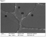
- FIG 1 Microstructure of Steel 3 according to the invention, showing Tungsten and Niobium euthectic carbides.
- Figure 2 Visual comparison of carbides precipitation before ( Figure 2a ) and after ageing heat treatment ( Figure 2b ) of Steel 3 according to the invention.
- Figure 3 Scheme of keelblock test sample. The area of extraction of the samples is indicated. The measurements are provided in millimetres: Measurements (mm) u v x y Z 25 55 40 140 140 140
- Figure 4 Scheme of test specimens for long term creep testing, with detailed measurements, provided in mm.
- ⁇ refers to diameter.
- R2 refers to a radius of 2 mm.
- M12 refers to thread type M12.
- Figure 5 Scheme of test specimens for creep crack growth rate testing, with detailed measurements, provided in mm. ⁇ refers to diameter.
- Figure 6 Scheme of test sample for thermal fatigue, with detailed measurements, provided in mm. ⁇ refers to diameter.
- R3 refers to a radius of 3 mm.
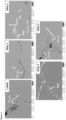
- Figure 7 Microstructure of samples of Steels 1, 2, 3, 4 and 5 according to the invention.
- microstructure images were taken with a field emission scanning electron microscope (FE-SEM); Ultra Plus by Zeiss (DE).
- Refractory stainless steels are well-known by their balance of high temperature mechanical properties in a corrosive environment supporting significant loads, at an affordable price and are used in mass production of industrial components.
- the present invention provides new refractory steels, to achieve higher values of deformation resistance to constant loads at high temperature even when a crack has been initiated (creep and crack growth rate), in comparison with reference steels such as 1.4848 refractory steel.
- the present invention refers to a refractory steel, comprising, in weight percentages based on the total weight of the steel:
- P phosphorus
- S sulphur
- Phosphorus and sulphur are generally each comprised in an amount of 0.03 wt. % or less.
- the condition that the sum of weight percentages of Molybdenum, Tungsten and Niobium is between 0.5 - 4.0 wt. % means that, if e.g. Tungsten and Niobium are absent or at extremely low concentrations, e.g. below 0.05 wt. %, Molybdenum is necessarily present at an amount of between 0.5 and 4.0 wt. %.
- the sum of weight percentages of Molybdenum, Tungsten and Niobium is between 0.6 and 4.0 wt. %, between 0.6 and 3.0 wt. %, between 0.6 and 2.8 wt. %, between 2.0 and 3.0 wt. %, between 2.5 and 3 wt. % or between 2.5 and 2.8 wt. %.
- the Tungsten content (given in weight percentage) in the refractory steel of the invention is between 2 and 4 times the Niobium content and between 2 and 4 times the Molybdenum content, one independently from one another. That is, as way of clarification, and without limitation, if e.g. the Tungsten content in the refractory steel is 1.5 wt. %, the Niobium and Molybdenum contents will be each, independently, between 0.375 and 0.75 wt. % (between a 1 ⁇ 4 and 1 ⁇ 2 the content of Tungsten).
- Tungsten content (given in weight percentage) of between 3 and 4 times the Niobium content, or between 3 and 3.5 times the Niobium content, and of between 2 and 3 times the Molybdenum content, or of between 2.5 and 3 times the Molybdenum content.
- the Nickel content in the refractory steel of the invention is between 20 and 26 wt.%, between 20 and 25 wt.%, between 20 and 22 wt. % or between 24 and 25 wt. %.
- the Chrome content in the refractory steel of the invention is between 19 and 25 wt. %, between 19 and 22 wt. %, between 21 and 25 wt. %, between 21 and 23 wt. %, between 24 and 25 wt. %.
- Silicon content is between 1.5 and 2 wt %, between 1.5 and 1.8 wt. %, between 1.6 and 1.8 wt. %, between 1.6 and 1.7 wt. %, or between 1.7 and 1.8 wt. %.
- the Manganese content in the refractory steel of the invention is between 0.5 and 1 wt %, between 0.8 and 1 wt %, or between 0.9 and 1 wt. %.
- the Carbon content in the refractory steel of the invention is between 0.5 and 0.7 wt.%, between 0.4 and 0.6 wt.%, between 0.5 and 0.7 wt.%, or between 0.5 and 0.6 wt.%.
- Additional particular embodiments of the present invention refer to a refractory steel wherein the Molybdenum content is between 0.5 and 0.8 wt. %, between 0.55 and 0.65 wt. %, or between 0.6 and 0.7 wt. %.
- a refractory steel having a Tungsten content of between 1 and 2 wt %, between 1.3 and 1.8 wt. %, between 0 and 1.7 wt. %, between 0 and 0.3 wt. %, between 0 and 0.1 wt. %, or between 1.4 and 1.7 wt. %.
- the Niobium content in the refractory steel of the present invention is between 0 and 0.8 wt. %, between 0 and 0.6 wt. %, between 0.4 and 0.8 wt. %, between 0.4 and 0.6 wt %, between 0.4 and 0.5 wt. %, between 0 and 0.5 wt. %, between 0 and 0.3 %, or between 0 and 0.1 wt. %.
- An embodiment of the present invention is also a refractory steel consisting of the following elements, in weight percentages based on the total weight of the steel:
- the present invention encompasses a refractory steel comprising:
- the present invention also encompasses a refractory steel comprising:
- a refractory steel comprising:
- a further refractory steel within the scope of the invention comprises:
- the inventors of the present invention have achieved to improve creep properties of the refractory steel according to the present invention, by increasing carbon content, thus generating a higher number of chrome carbides, which are further stabilized with the introduction of Molybdenum in certain ranges.
- the inventors have achieved to further improve these properties by the introduction of different quantities of Tungsten (W) and Niobium (Nb), in particular amounts, and in preferred relationship one with another, which unexpectedly has generated high temperature strengthening phases.
- the refractory steels of the invention having increased carbon content and comprising Molybdenum presents a microstructure, which consists of a matrix of austenite, with variable quantities of carbides.
- the introduction of Tungsten and Niobium has been observed to unexpectedly generate eutectic carbides in grain boundaries, which, without wishing to be bound to theory, seems to be behind the reduction in the deformation and cracks propagation (see Figure 1 ).
- the refractory steels of the present invention can be used for e.g. for manufacturing complex components integrated in furnaces that can work continuously and discontinuously, using radiation tubes, electrical resistances, or open burners inside the equipment to heat the load. They can be used in cyclic or static loads in the range of 20-50 MPa, at temperatures from 600-1000°C. These refractory steels are prepared to withstand wear conditions due to the stability at high temperature given by the Molybdenum, Niobium and Tungsten carbides in a corrosive environment consisting of combustion gases or dry air conditions.
- the invention provides a process for the preparation of the refractory steel defined above, which comprises the following steps:
- the charge may be maintained in its molten condition for any desired time, but for energy saving purposes, will not be maintained in its molten condition for more than 10 minutes, but maintaining for a longer time would not be detrimental to the refractory steel.
- the molten condition is maintained for between 3 and 10 minutes or between 4 and 8 minutes.
- Step (vi) is an ageing heat treatment, to increase wear and creep resistance properties.
- the introduction of the ageing heat treatment assures the precipitation of a homogeneous network of carbides inside grains, assuring a higher wear resistance (see Fig 2 ).
- the furnace is a conventional furnace, such as an Open-air medium frequency induction furnace or vacuum Induction Melting (VIM) furnace.
- a conventional furnace such as an Open-air medium frequency induction furnace or vacuum Induction Melting (VIM) furnace.
- the term “calm air” refers to an environment in absence or nearly absence of air currents or wind, i.e, wind or air currents moving at less than 1 knot, or “zero” (0) on the international scale of wind force known as “Beaufort scale”.
- the temperature in “calm air” conditions is intended to be ambient or room temperature, taken in the broad sense, i.e. generally between 15 and 30 °C, more specifically between 20 and 27 °C, or between 20 and 25 °C, or between 20 and 22°C.
- the alloying elements Mn, Al, Si, Fe and C may be added to the furnace in step (i) in the following forms:
- the W content is about 2-4 times the Nb content, and about 2-4 times of the Mo content.
- the heating or temperature increasing of step (ii) is carried out progressively.
- the heating is carried out by increasing the power of the furnace progressively to higher power, over at least 20 - 30 minutes, to assure no refractory cracking takes place during heating up.
- the time to reach the final temperature of the mixture obtained in step (i) is not relevant, although it is recommended, as noted above, to heat the mixture progressively.
- the time to reach the final temperature may be between 20 minutes and e.g 10 or 5 hours.
- the time to reach the final temperature is between 20 minutes and 3 hours, between 20 minutes and 1 hour, or between 20 minutes and 30 minutes.
- the average heating rate during step (ii) should be between 1 °C/min and 90 °C/min, according to particular embodiments is between 10 and 85 °C/min, or between 25°C/min and 85°C, or between 50 °C/min and 85 °C/min.
- the mixture of elements is heated up to between 1550 and 1700°C, for example to about 1650°C, so that sufficient homogenization of the charge takes place.
- the mixture Before pouring the melt into the mould, the mixture must remain molten for a period of time, to allow a correct homogenization of the elements. Typically, time is not less than between 3 and 10 minutes. Then from 0.05 to 0.30 wt. % of FeSiCa (preferably, from 0.05 to 0.15 wt. %) and from 0.05 to 0.10 wt.% of pure aluminum are added into the furnace to assure a correct deoxidation of the metal. The molten mixture is transferred to a tea pot ladle that previously has been heated up with a gas torch. The melt is poured directly into a keel-block mold, manufactured with chemically bonded sand.
- the process for preparing the refractory steel of the invention further comprises submitting the refractory steel of the invention to a heat treatment (see step (vi)), which is designated as an ageing heat treatment.
- This heat treatment process can be carried out in any conventional manner known to the skilled person and comprises the steps of: submitting the high creep resistant refractory steel of the invention as-cast to a high temperature, and subsequently cooling, this heat treatment is known as ageing and deals with the precipitation of secondary carbides that enhances high temperature mechanical properties.
- the heat treatment is done in a furnace, such as for example an electrical resistance non-controlled atmosphere heat treatment furnace.
- the ageing treatment applied consists in heating up the metallic sample, preferably a keel-block sample (see Figure 1 ), to a temperature of between 780-1000°C; preferred temperature ranges are between 820 and 950 °C, between 835 and 930 °C, for example at about 930°C.
- the time the refractory steel as cast is submitted to heat treatment varies depending on factors like the size of the part, the selected temperature, and is typically from 1 to 30 hours, for example during between 1 and 20 hours, between 1 and 10 hours, between 1 and 5 hours, between 1.5 and 2.5 hours, for example during about 2 hours, in a 11 kW power Termolab furnace with open air atmosphere.
- the metallic sample is extracted from the furnace and cooled down in calm air until reaching room temperature.
- This ageing heat treatment represents a significant advance in comparison with the current delivery conditions of refractory stainless steels.
- the controlled precipitation of secondary carbides allows that initial wear is lower and crack initiation and growth is slower. This effect is due to the presence of carbides in the microstructure non-generating a preliminary high wear rate and assuring higher mechanical resistance to crack initiation.
- the present invention is also related to a machinery part comprising the refractory steel as-cast or the heat-treated refractory steel of the invention.
- the heat-treated high creep resistant refractory steels are preferably but non-limiting to examples of parts such as radiation tubes for heat treatment furnaces, buckets to contain parts in heat treatment furnaces used in the steel and aluminium flat product, beams, and rolls for parts transport in hot stamping sector, trays and rails in the investment casting and ceramic sector and entrance and outside segments in the mining and cement roasting furnaces.
- Table 1 Examples of the refractory steels according to the present invention are gathered in Table 1; the steels represented in the table 1 have gone over different high temperature related validation tests, such as long term creep, thermal fatigue and creep crack growth rate.
- Table 1 Chemical composition of high creep resistant refractory steel (wt. %) Refractory Steel Chemical composition (wt.
- Example 1 preparation of Steel 1, Steel 2, Steel 3 and Steel 4 according to the present invention
- the metal was maintained molten for about 4 minutes.
- the mixture of metals was transferred to a tea pot ladle, heated up with a gas burner. Pouring was performed into keel blocks Y2, particularly chemically bonded sand moulds, following the standard norm UNE-EN 1563:1998; the casted keel blocks Y2 were then extracted from the moulds and cleaned by shot blasting.
- the obtained samples were submitted to a heat treatment consisting in heating up the sample, from room temperature to 930 °C, and maintaining it at 930°C during about 2 hours, in a 11kW power Termolab furnace, with non-controlled atmosphere.
- the heat treated samples were taken out from the furnace and cooled down, in calm air, until reaching room temperature, thus obtaining samples for subsequent testing.
- Example 2 Mechanical properties and ageing heat treatment process of the steels according to the present invention
- the keel blocks were cut and test samples for micrographic inspection of rectangular dimensions of approximately 25 x 20 x 20 mm were prepared by surface polishing and their microstructures were then analysed with a field emission gun scanning electron microscope (SEM) (Model ULTRA PLUS, Zeiss).
- SEM field emission gun scanning electron microscope
- Test samples for short creep and long creep were machined from the bottom rectangular part of the keel block of each of the refractory steels, of dimensions 25*40*140 mm, according to the dimensions indicated in Figure 4 , and were tested according to EN-ISO 204 standard.
- Test samples for creep crack growth rate were machined from the bottom rectangular part of the keel block of each of the refractory steels, of dimensions 25*40*140 mm, according to the dimensions indicated in Figure 5 .
- Test samples for thermal fatigue tests were machined from the bottom rectangular part of the keel block of each of the refractory steels, of dimensions 25*40*140 mm, according to the dimensions indicated in Figure 6 .
- Table 2 below shows how Steel 1, Steel 2, Steel 3 and Steel 4, which are according to the present invention, present significantly better results, in comparison to the reference refractory steel 1.4848, in terms of long term creep.
- Table 2 Long term creep properties at 930 °C at different loads Refractory Steel Time to rupture in hours at 48 MPa Time to rupture in hours at 25 MPa 1.4848 refractory steel (comparative) 38,25 636,25 Steel 1 47,75 2500 Steel 2 69,25 4230,5 Steel 3 236,25 >5000 Steel 4 68 3869
- Table 3 shows how Steel 1, Steel 2 and Steel 3 according to the present invention present better results in terms of creep crack growth rates, at different loads, than comparative 1.4848 refractory steel; Steel 4 in terms of creep crack growth rate shows a performance which is similar to comparative 1.4848 refractory steel.
- Table 3 Creep crack growth rates at different loads Refractory Steel Hours before breaking at 110 MPa Hours before breaking at 90 MPa 1.4848 refractory steel (comparative) 32 146,25 Steel 1 67,17 196,12 Steel 2 102,33 469,92 Steel 3 62,83 215,8 Steel 4 35,25 150,67
- Table 4 below shows how Steel 1 shows better thermal fatigue resistance at thermal cycles from 700 to 300°C, in comparison to comparative 1.4848 refractory steel. The table gathers the average of 8 samples tested under the same conditions. Table 4: Time until failure for test samples submitted to thermal cycles from 700 to 300°C Refractory steel External diameter of the test bar (mm) Internal diameter of the test bar (mm) Time to rupture (hours). 1.4848 refractory steel 8 2,4 567 Steel 1 8 2,4 955
Landscapes
- Chemical & Material Sciences (AREA)
- Engineering & Computer Science (AREA)
- Materials Engineering (AREA)
- Metallurgy (AREA)
- Organic Chemistry (AREA)
- Mechanical Engineering (AREA)
- Manufacturing & Machinery (AREA)
- Physics & Mathematics (AREA)
- Thermal Sciences (AREA)
- Crystallography & Structural Chemistry (AREA)
- Treatment Of Steel In Its Molten State (AREA)
Priority Applications (1)
| Application Number | Priority Date | Filing Date | Title |
|---|---|---|---|
| EP23382534.8A EP4471171A1 (fr) | 2023-06-02 | 2023-06-02 | Aciers réfractaires résistant au fluage |
Applications Claiming Priority (1)
| Application Number | Priority Date | Filing Date | Title |
|---|---|---|---|
| EP23382534.8A EP4471171A1 (fr) | 2023-06-02 | 2023-06-02 | Aciers réfractaires résistant au fluage |
Publications (1)
| Publication Number | Publication Date |
|---|---|
| EP4471171A1 true EP4471171A1 (fr) | 2024-12-04 |
Family
ID=86693041
Family Applications (1)
| Application Number | Title | Priority Date | Filing Date |
|---|---|---|---|
| EP23382534.8A Pending EP4471171A1 (fr) | 2023-06-02 | 2023-06-02 | Aciers réfractaires résistant au fluage |
Country Status (1)
| Country | Link |
|---|---|
| EP (1) | EP4471171A1 (fr) |
Citations (4)
| Publication number | Priority date | Publication date | Assignee | Title |
|---|---|---|---|---|
| GB1241081A (en) * | 1968-01-05 | 1971-07-28 | Abex Corp | Iron-nickel-chromium alloys |
| US4861547A (en) * | 1988-04-11 | 1989-08-29 | Carondelet Foundry Company | Iron-chromium-nickel heat resistant alloys |
| EP1043417A1 (fr) * | 1999-04-05 | 2000-10-11 | Hitachi Metals, Ltd. | Composant de système d'échappement et procédé de fabrication |
| EP1741799A1 (fr) * | 2004-04-19 | 2007-01-10 | Hitachi Metals, Ltd. | ACIER COULÉ AUSTÉNITIQUE À FORTE TENEUR EN Cr-Ni RÉSISTANT À LA CHALEUR ET COMPOSANT DE SYSTÈME D'ÉCHAPPEMENT PRODUIT À PARTIR DE CELUI-CI |
-
2023
- 2023-06-02 EP EP23382534.8A patent/EP4471171A1/fr active Pending
Patent Citations (4)
| Publication number | Priority date | Publication date | Assignee | Title |
|---|---|---|---|---|
| GB1241081A (en) * | 1968-01-05 | 1971-07-28 | Abex Corp | Iron-nickel-chromium alloys |
| US4861547A (en) * | 1988-04-11 | 1989-08-29 | Carondelet Foundry Company | Iron-chromium-nickel heat resistant alloys |
| EP1043417A1 (fr) * | 1999-04-05 | 2000-10-11 | Hitachi Metals, Ltd. | Composant de système d'échappement et procédé de fabrication |
| EP1741799A1 (fr) * | 2004-04-19 | 2007-01-10 | Hitachi Metals, Ltd. | ACIER COULÉ AUSTÉNITIQUE À FORTE TENEUR EN Cr-Ni RÉSISTANT À LA CHALEUR ET COMPOSANT DE SYSTÈME D'ÉCHAPPEMENT PRODUIT À PARTIR DE CELUI-CI |
Similar Documents
| Publication | Publication Date | Title |
|---|---|---|
| EP3287540B2 (fr) | Acier thermorésistant austénitique cr-mn-n et son procédé de fabrication | |
| CN109988971B (zh) | 一种生产特超级纯净高速工具钢的方法 | |
| CN110306108A (zh) | 一种高韧性高抗裂性热作模具钢及其制造方法 | |
| KR20090043555A (ko) | 가벼운 구조체를 제조하기 위한 강판 및 그 강판을 제조하는 방법 | |
| KR20190046729A (ko) | 지열 발전 터빈 로터용 저합금강 및 지열 발전 터빈 로터용 저합금 물질, 및 이들의 제조 방법 | |
| US20240068078A1 (en) | Die steel with a high thermal diffusion coefficient and its preparation methods | |
| CN114032440A (zh) | 一种Laves相强化奥氏体耐热钢及其制备方法 | |
| CN101942606A (zh) | 含氮奥氏体型热作模具钢及其制备方法 | |
| CN114717467A (zh) | 一种过共晶高铬铸铁材料、制备方法及其应用 | |
| CN116536586A (zh) | 一种耐低温高强高韧奥氏体不锈钢及其制备方法 | |
| CN106566953A (zh) | 一种耐腐蚀合金锻件及其生产方法 | |
| CN112159932A (zh) | 超高强度稀土4340钢的制造方法 | |
| CN114000027B (zh) | Uns n08120锻环及其制造方法 | |
| JPH08333657A (ja) | 耐熱鋳鋼およびその製造方法 | |
| CN107267778B (zh) | 一种炼镁还原罐及其制作方法 | |
| JP7610244B2 (ja) | 低熱膨張合金 | |
| CN114150207A (zh) | 高强度Ni-Fe基时效硬化型耐蚀合金及制备方法 | |
| EP4471171A1 (fr) | Aciers réfractaires résistant au fluage | |
| CN119753526A (zh) | 一种高强高耐蚀超级奥氏体不锈钢及其制备方法 | |
| WO2021201142A1 (fr) | ALLIAGE Ni-Cr-Mo-Nb | |
| CN116043106B (zh) | 一种高纯净度高韧性长服役周期冷作模具钢及其制备方法 | |
| CN110343907A (zh) | 含W的高强度铸造Ni3Al基高温合金及其制备方法 | |
| CN118563170A (zh) | 一种压缩机用镍基合金及其转子锻坯的制备方法 | |
| JP2020509225A (ja) | 極低温用高強度オーステナイト系耐食性溶接構造用鋼材および製造方法 | |
| CN119351854B (zh) | 一种沉淀硬化型不锈钢及其制备方法 |
Legal Events
| Date | Code | Title | Description |
|---|---|---|---|
| PUAI | Public reference made under article 153(3) epc to a published international application that has entered the european phase |
Free format text: ORIGINAL CODE: 0009012 |
|
| STAA | Information on the status of an ep patent application or granted ep patent |
Free format text: STATUS: THE APPLICATION HAS BEEN PUBLISHED |
|
| AK | Designated contracting states |
Kind code of ref document: A1 Designated state(s): AL AT BE BG CH CY CZ DE DK EE ES FI FR GB GR HR HU IE IS IT LI LT LU LV MC ME MK MT NL NO PL PT RO RS SE SI SK SM TR |
|
| STAA | Information on the status of an ep patent application or granted ep patent |
Free format text: STATUS: REQUEST FOR EXAMINATION WAS MADE |
|
| 17P | Request for examination filed |
Effective date: 20250604 |