EP4471190A1 - Dispositif de croissance de monocristal - Google Patents
Dispositif de croissance de monocristal Download PDFInfo
- Publication number
- EP4471190A1 EP4471190A1 EP22923311.9A EP22923311A EP4471190A1 EP 4471190 A1 EP4471190 A1 EP 4471190A1 EP 22923311 A EP22923311 A EP 22923311A EP 4471190 A1 EP4471190 A1 EP 4471190A1
- Authority
- EP
- European Patent Office
- Prior art keywords
- reflection member
- reflection
- receiving module
- light
- transmission channel
- Prior art date
- Legal status (The legal status is an assumption and is not a legal conclusion. Google has not performed a legal analysis and makes no representation as to the accuracy of the status listed.)
- Granted
Links
Images


Classifications
-
- C—CHEMISTRY; METALLURGY
- C30—CRYSTAL GROWTH
- C30B—SINGLE-CRYSTAL GROWTH; UNIDIRECTIONAL SOLIDIFICATION OF EUTECTIC MATERIAL OR UNIDIRECTIONAL DEMIXING OF EUTECTOID MATERIAL; REFINING BY ZONE-MELTING OF MATERIAL; PRODUCTION OF A HOMOGENEOUS POLYCRYSTALLINE MATERIAL WITH DEFINED STRUCTURE; SINGLE CRYSTALS OR HOMOGENEOUS POLYCRYSTALLINE MATERIAL WITH DEFINED STRUCTURE; AFTER-TREATMENT OF SINGLE CRYSTALS OR A HOMOGENEOUS POLYCRYSTALLINE MATERIAL WITH DEFINED STRUCTURE; APPARATUS THEREFOR
- C30B15/00—Single-crystal growth by pulling from a melt, e.g. Czochralski method
- C30B15/20—Controlling or regulating
- C30B15/22—Stabilisation or shape controlling of the molten zone near the pulled crystal; Controlling the section of the crystal
- C30B15/26—Stabilisation or shape controlling of the molten zone near the pulled crystal; Controlling the section of the crystal using television detectors; using photo or X-ray detectors
-
- C—CHEMISTRY; METALLURGY
- C30—CRYSTAL GROWTH
- C30B—SINGLE-CRYSTAL GROWTH; UNIDIRECTIONAL SOLIDIFICATION OF EUTECTIC MATERIAL OR UNIDIRECTIONAL DEMIXING OF EUTECTOID MATERIAL; REFINING BY ZONE-MELTING OF MATERIAL; PRODUCTION OF A HOMOGENEOUS POLYCRYSTALLINE MATERIAL WITH DEFINED STRUCTURE; SINGLE CRYSTALS OR HOMOGENEOUS POLYCRYSTALLINE MATERIAL WITH DEFINED STRUCTURE; AFTER-TREATMENT OF SINGLE CRYSTALS OR A HOMOGENEOUS POLYCRYSTALLINE MATERIAL WITH DEFINED STRUCTURE; APPARATUS THEREFOR
- C30B15/00—Single-crystal growth by pulling from a melt, e.g. Czochralski method
- C30B15/30—Mechanisms for rotating or moving either the melt or the crystal
-
- C—CHEMISTRY; METALLURGY
- C30—CRYSTAL GROWTH
- C30B—SINGLE-CRYSTAL GROWTH; UNIDIRECTIONAL SOLIDIFICATION OF EUTECTIC MATERIAL OR UNIDIRECTIONAL DEMIXING OF EUTECTOID MATERIAL; REFINING BY ZONE-MELTING OF MATERIAL; PRODUCTION OF A HOMOGENEOUS POLYCRYSTALLINE MATERIAL WITH DEFINED STRUCTURE; SINGLE CRYSTALS OR HOMOGENEOUS POLYCRYSTALLINE MATERIAL WITH DEFINED STRUCTURE; AFTER-TREATMENT OF SINGLE CRYSTALS OR A HOMOGENEOUS POLYCRYSTALLINE MATERIAL WITH DEFINED STRUCTURE; APPARATUS THEREFOR
- C30B27/00—Single-crystal growth under a protective fluid
- C30B27/02—Single-crystal growth under a protective fluid by pulling from a melt
-
- C—CHEMISTRY; METALLURGY
- C30—CRYSTAL GROWTH
- C30B—SINGLE-CRYSTAL GROWTH; UNIDIRECTIONAL SOLIDIFICATION OF EUTECTIC MATERIAL OR UNIDIRECTIONAL DEMIXING OF EUTECTOID MATERIAL; REFINING BY ZONE-MELTING OF MATERIAL; PRODUCTION OF A HOMOGENEOUS POLYCRYSTALLINE MATERIAL WITH DEFINED STRUCTURE; SINGLE CRYSTALS OR HOMOGENEOUS POLYCRYSTALLINE MATERIAL WITH DEFINED STRUCTURE; AFTER-TREATMENT OF SINGLE CRYSTALS OR A HOMOGENEOUS POLYCRYSTALLINE MATERIAL WITH DEFINED STRUCTURE; APPARATUS THEREFOR
- C30B29/00—Single crystals or homogeneous polycrystalline material with defined structure characterised by the material or by their shape
- C30B29/02—Elements
- C30B29/06—Silicon
Definitions
- the invention relates to the technical field of crystal growth, and in particular to a single crystal growth device.
- a seed crystal is immersed in a raw material melt of silicon stored in a crucible in a chamber maintained in an inert gas environment under reduced pressure, and the immersed seed crystal is slowly pulled up, whereby single crystal silicon is grown below the seed crystal.
- an interval between a guide cylinder and liquid surface of the raw material melt of silicon in the crucible needs to be accurately controlled at a predetermined distance, but as the single crystal silicon rod grows continuously, the volume of the silicon melt in the crucible is reduced gradually, the liquid surface of the silicon melt drops continuously, and the interval between the guide cylinder and the liquid surface of the raw material melt of silicon in the crucible changes, which may affect the growth control of the crystal and the quality of the crystal. In the related art, the change of the liquid surface of the melt cannot be accurately judged, which directly affects the growth quality of the single crystal.
- the invention provides a single crystal growth device, which may accurately observe a liquid level of a melt in a crucible, so as to ensure a growth quality of a single crystal.
- a single crystal growth device includes: a furnace body, inside which a furnace chamber is defined; a crucible, disposed in the furnace chamber in a liftable manner; a guide cylinder, located in the furnace chamber and above the crucible, a channel suitable for a crystal rod to pass through is disposed in a center of the guide cylinder, a first light transmission channel and a second light transmission channel which form a certain included angle and are communicated are formed in the guide cylinder, a light outlet hole communicating with the first light transmission channel and a light inlet hole communicating with the second light transmission channel are formed on the guide cylinder, and an area, opposite to the light inlet hole, of a junction position of an inner peripheral wall of the crucible and the melt in the crucible is a detection area; a reflection module, including a first reflection member, the first reflection member is disposed at a communication position of the first light transmission channel and the second light transmission channel, and the first reflection member is suitable for reflecting and turning a light entering the second light transmission channel into
- the first light transmission channel and the second light transmission channel which form the certain included angle and are communicated are formed in the guide cylinder, the light outlet hole communicating with the first light transmission channel and the light inlet hole communicating with the second light transmission channel are formed on the guide cylinder, and the area, opposite to the light inlet hole, of the junction position of the inner peripheral wall of the crucible and the melt in the crucible is the detection area, and the image of the detection area is suitable for entering the image receiving module after being reflected by the reflection module.
- a worker may timely know the change of the position height of the liquid surface of the melt in the crucible through the change of the image received by the image receiving module, which is convenient for the worker to raise or lower the crucible according to current position height of the liquid surface of the melt, so as to accurately control a vertical interval between the liquid surface of the melt and the guide cylinder in a set distance, which is beneficial for ensuring the growth quality of the single crystal.
- the first reflection member is a polished silicon sheet or a polished molybdenum sheet.
- the first light transmission channel in a direction from the first reflection member to the light outlet hole, the first light transmission channel extends obliquely upwards in a direction deviating from the crystal rod; and in a direction from the first reflection member to the light inlet hole, the second light transmission channel extends obliquely downwards in the direction deviating from the crystal rod.
- the light inlet hole and the light outlet hole are respectively located on two opposite sides along an up-down direction of the guide cylinder.
- the image receiving module and the detection area are located on a same side in a radial direction of the crystal rod, and the light outlet hole faces towards the image receiving module.
- the reflection module further includes: at least one second reflection member disposed above the first reflection member, and a reflection light of the first reflection member is suitable for entering the image receiving module after being reflected by the second reflection member.
- the image receiving module and the detection area are located on two opposite sides in a radial direction of the crystal rod, and the image of the detection area is suitable for entering the image receiving module by bypassing the crystal rod after being reflected by the first reflection member and the second reflection member.
- a plurality of second reflection members are provided, the plurality of second reflection members are distributed at intervals along a circumferential direction of the guide cylinder, the plurality of second reflection members are distributed at intervals along an up-down direction, and the reflection light of the first reflection member is suitable for entering the image receiving module by bypassing the crystal rod after being reflected by the plurality of second reflection members in sequence.
- two second reflection members are provided, which are defined as a primary reflection member and a secondary reflection member, the primary reflection member is located on a right upper side of the first reflection member, and the primary reflection member is suitable for obliquely upwards reflecting the reflection light of the first reflection member towards a right rear side; the secondary reflection member is located on an upper side of the primary reflection member, the secondary reflection member is located on the right rear side of the primary reflection member, and the secondary reflection member is suitable for obliquely upwards reflecting a reflection light of the primary reflection member towards a left rear side.
- annular guide rail is disposed at an inner side of a top wall of the furnace body, the annular guide rail defines a sliding groove, a slider is disposed at a top of the image receiving module, the slider is embedded in the sliding groove, and the slider is suitable for sliding along an extending direction of the annular guide rail, so as to adjust a relative position of the image receiving module and the reflection module in a circumferential direction of the furnace body.
- the image receiving module includes: a first sub-receiving module, in which an accommodating cavity is defined, and an opening is formed at a bottom of the accommodating cavity; and a second sub-receiving module, slidably connected with the first sub-receiving module, and the second sub-receiving module is suitable for moving between a first position contained in the accommodating cavity and a second position extending out of the opening, so as to adjust a relative position of the second sub-receiving module and the reflection module in an axial direction of the furnace body.
- the invention below provides a number of different embodiments or examples for implementing different structures of the invention.
- the components and settings of a particular example are described below. Of course, they are only examples and are not intended to limit the invention.
- the invention may repeat reference numbers and/or letters in different examples. Such repetition is for the purpose of simplification and clarity, and does not in itself indicate the relationship between the various embodiments and/or settings discussed.
- the invention provides examples of various specific processes and materials, but those of ordinary skill in the art may be aware of the application of other processes and/or the use of other materials.
- a single crystal growth device 100 according to an embodiment of the invention will be described below with reference to the accompanying drawings.
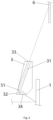
- a single crystal growth device 100 includes a furnace body 1, a crucible 2, a guide cylinder 3, a reflection module and an image receiving module 6.
- a furnace chamber 11 is defined in the furnace body 1, the crucible 2 is disposed in the furnace chamber 11 in a liftable manner, the guide cylinder 3 is located in the furnace chamber 11 and above the crucible 2, and a channel suitable for a crystal rod 4 to pass through is disposed in a center of the guide cylinder 3.
- a single crystal silicon rod may be produced through the single crystal growth device 100, first, a polycrystal is placed in the crucible 2 to be heated to form a melt 21 containing silicon, a seed crystal is impregnated in the melt 21, and by lifting and rotating the seed crystal, silicon atoms in the melt 21 crystallize at the bottom of the seed crystal.
- the diameter of the single crystal silicon rod may be controlled by controlling the lifting speed and/or rotation speed of the crystal rod 4.
- the diameter of the single crystal silicon rod may be reduced by improving the lifting speed or rotation speed of the crystal rod 4, and the growth speed of single crystal silicon may be suppressed by increasing the temperature of the melt 21.
- the diameter of the single crystal silicon rod may be enlarged by reducing the lifting speed and/or rotation speed of the crystal rod 4, and the growth speed of single crystal silicon may be accelerated by decreasing the temperature of the melt 21.
- the single crystal growth device 100 further includes a clamping device 7, the clamping device 7 is disposed in the furnace chamber 11 in a liftable and rotatable manner, the clamping device 7 is suitable for fixing the upper end of the crystal rod 4, and the clamping device 7 may drive the crystal rod 4 to lift, lower and rotate along an axial direction of the guide cylinder 3.
- the inert gas such as argon
- the inert gas may be introduced downwards through an interval between the outer peripheral side of the crystal rod 4 and the guide cylinder 3, and the inert gas enters between the guide cylinder 3 and liquid surface of the melt 21 after flowing downwards, and flows towards the radial outer side of the guide cylinder 3, so as to maintain the inert gas environment under reduced pressure in the furnace chamber 11.
- the vertical interval between the guide cylinder 3 and the liquid surface of the melt 21 needs to be accurately controlled, meanwhile, in the growth process of the single crystal, the vertical interval between the guide cylinder 3 and the liquid surface of the melt 21 needs to be kept at a set value.
- silicon content in the melt 21 is continuously reduced to lead to continuous lowering of height position of the liquid surface of the melt 21, further enlarging the vertical interval between the guide cylinder 3 and the liquid surface of the melt 21.
- an image of a detection area is suitable for entering the image receiving module 6 after being reflected by the reflection module
- the detection area herein refers to a junction position of an inner peripheral wall of the crucible 2 and the melt 21 in the crucible 2, which may be reflected by the reflection module, so that a worker may timely know the change of position height of the liquid surface of the melt 21 in the crucible 2 through the change of the image received by the image receiving module 6, which is convenient for the worker to adjust the height of the crucible 2 according to current position height of the liquid surface of the melt 21, so as to accurately control the interval between the liquid surface of the melt 21 and the guide cylinder 3 in the set value, which is beneficial for ensuring the growth quality of the single crystal.
- an incident angle of an incident light of the detection area on a first reflection member 51 is greater than a standard incident angle, according to the reflection principle, a reflection angle is equal to the incident angle, then the position height of an image formed on the image receiving module 6 finally is higher than a standard height, that is, when the height of the image collected by the image receiving module 6 is higher than the standard height, the liquid surface of the melt 21 is lower than the standard position.
- the incident angle of the incident light of the detection area on the first reflection member 51 is smaller than the standard incident angle, according to the reflection principle, the reflection angle is equal to the incident angle, then the position height of the image formed on the image receiving module 6 finally is lower than the standard height, that is, when the height of the image collected by the image receiving module 6 is lower than the standard height, the liquid surface of the melt 21 is higher than the standard position.
- the interval between the liquid surface of the melt 21 and the guide cylinder 3 is smaller than the set value, then by controlling the crucible 2 to lower, namely, the crucible 2 to move in a direction away from the guide cylinder 3, the interval between the liquid surface of the melt 21 and the guide cylinder 3 is gradually enlarged till meeting the set distance.
- the silicon content in the melt 21 is continuously reduced to lead to continuous lowering of position height of the liquid surface of the melt 21 in the crucible 2, therefore, when it is learned through the image receiving module 6 that the position height of the liquid surface of the melt 21 is lower than the set value, by controlling the crucible 2 to rise, namely, the crucible 2 to move in a direction close to the guide cylinder 3, the interval between the liquid surface of the melt 21 and the guide cylinder 3 is gradually shortened till meeting the set distance.
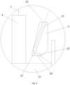
- a first light transmission channel 31 and a second light transmission channel 32 which form a certain included angle and are communicated are formed in the guide cylinder 3
- a light outlet hole 33 communicating with the first light transmission channel 31 and a light inlet hole 34 communicating with the second light transmission channel 32 are formed on the guide cylinder 3
- an area, opposite to the light inlet hole 34, of the junction position of the inner peripheral wall of the crucible 2 and the melt 21 in the crucible 2 is the detection area
- the reflection module includes a first reflection member 51, the first reflection member 51 is disposed at a communication position of the first light transmission channel 31 and the second light transmission channel 32, and the first reflection member 51 is suitable for reflecting and turning a light entering the second light transmission channel 32 into the first light transmission channel 31.
- an image of the detection area enters the second light transmission channel 32 through the light inlet hole 34, after reflection of the first reflection member 51, a light entering the first light transmission channel 31 is propagated towards the outside of the guide cylinder 3 through the light outlet hole 33, the first reflection member 51, the first light transmission channel 31 and the second light transmission channel 32 are disposed in the guide cylinder 3, therefore, the first reflection member 51 may fully utilize inside space of the guide cylinder 3, namely, mounting space of the first reflection member 51 is saved, meanwhile, light is seldom interfered by outside in the first light transmission channel 31 and the second light transmission channel 32, so that the image receiving module 6 may clearly and completely receive image information of the detection area, which is beneficial for improving accuracy of judging the change of position height of liquid surface of the melt 21. Meanwhile, the guide cylinder 3 may isolate part of heat, so that the first reflection member 51 located inside the guide cylinder 3 is seldom influenced by the high-temperature environment in the furnace chamber 11, which is beneficial for improving reliability of the first reflection member 51.
- the first light transmission channel 31 and the second light transmission channel 32 which form the certain included angle and are communicated are formed in the guide cylinder 3
- the light outlet hole 33 communicating with the first light transmission channel 31 and the light inlet hole 34 communicating with the second light transmission channel 32 are formed on the guide cylinder 3
- the area, opposite to the light inlet hole 34, of the junction position of the inner peripheral wall of the crucible 2 and the melt 21 in the crucible 2 is the detection area
- the image of the detection area is suitable for entering the image receiving module 6 after being reflected by the reflection module.
- the reflection principle when the height of the image collected by the image receiving module 6 is higher than the standard height, it indicates that the liquid level of the melt 21 is lower than the standard position, when the height of the image collected by the image receiving module 6 is lower than the standard height, it indicates that the liquid level of the melt 21 is higher than the standard position, thus a worker may timely know the change of position height of liquid level of the melt 21 in the crucible 2 through the change of the image received by the image receiving module 6, which is convenient for the worker to raise or lower the crucible 2 according to the current position height of the liquid surface of the melt 21, so as to accurately control the vertical interval between the liquid surface of the melt 21 and the guide cylinder 3 in the set distance, which is beneficial for ensuring the growth quality of the single crystal.
- the first reflection member 51 is a polished silicon sheet or a polished silicon molybdenum sheet.
- the polished silicon sheet or polished molybdenum sheet has a mirror effect, with good reflection effect.
- the silicon sheet and the molybdenum sheet both have excellent high temperature resistance, so that the first reflection member 51 may adapt to the high temperature environment in the furnace chamber 11, so as to avoid the change of the reflection angle and the like caused by deformation of the first reflection member 51 under high temperature, thus promoting the reliability of the first reflection member 51.
- the polished silicon sheet may serve as the first reflection member 51, thus avoiding that the first reflection member 51 pollutes the growth of the single crystal silicon.
- an inner diameter of the second light transmission channel 32 is enlarged That is, the inner diameter of the end, close to the first reflection member 51, of the second light transmission channel 32 is smaller than the inner diameter of the end, away from first reflection member 51, so that the first reflection member 51 may receive light in a wider range through the second light transmission channel 32, thereby expanding the area of the detection area. Therefore, the length of the detection area is prolonged therewith in an up-down direction, which is beneficial for improving the change range of position height of liquid surface of the melt 21 that may be received by image receiving module 6.
- the first light transmission channel 31 in a direction from the first reflection member 51 to the light outlet hole 33, the first light transmission channel 31 extends obliquely upwards in a direction deviating from the crystal rod 4, and in a direction from the first reflection member 51 to the light inlet hole 34, the second light transmission channel 32 extends obliquely downwards in the direction deviating from the crystal rod 4.
- both the first light transmission channel 31 and the second light transmission channel 32 extend towards a radial outer side of the crystal rod 4 relative to the first reflection member 51, the detection area, the light inlet hole 34 and the light outlet hole 33 are all located on a side, away from the crystal rod 4, of the first reflection member 51, the detection area and the light inlet hole 34 are located obliquely below the first reflection member 51, the light outlet hole 33 is located obliquely above the first reflection member 51, so that the image of the detection area is incident on the first reflection member 51 towards an oblique upward direction close to the crystal rod 4, the reflected light of the first reflection member 51 is directed obliquely upward and away from the crystal rod 4, and is propagated outwards through the light outlet hole 33, that is, is reflected in a direction away from the crystal rod 4, therefore, it may better avoid interference of the crystal rod 4 or the clamping device 7 on the reflected light of the first reflection member 51, so that the image receiving module 6 may receive complete image information of the detection area, which is beneficial for
- the light inlet hole 34 and the light outlet hole 33 are respectively located on two opposite sides along the up-down direction of the guide cylinder 3. Specifically, the light inlet hole 34 is disposed on the side, facing the liquid surface of the melt 21, of the guide cylinder 3, the light outlet hole 33 is disposed on the side, away from the liquid surface of the melt 21, of the guide cylinder 3, the upper end of the first light transmission channel 31 communicates with the light outlet hole 33, the lower end of the first light transmission channel 31 communicates with the upper end of the second light transmission channel 32, and the lower end of the second light transmission channel 32 communicates with the light inlet hole 34. Therefore, the reflected light of the first reflection member 51 may have a higher projection angle.
- the image receiving module 6 may be disposed at a higher position, for example, the image receiving module 6 may be disposed at the top of the furnace chamber 11, so that the image receiving module 6 is disposed away from the crucible 2, which may better avoid influence of the high temperature and the like on the image receiving module 6.
- the guide cylinder 3 is annular, a through hole for the crystal rod 4 to move up and down is formed in the middle of the guide cylinder 3, in a direction from bottom to top, the inner diameter of the through hole is enlarged gradually, the wall thickness of the guide cylinder 3 in the radial direction is reduced gradually after being enlarged gradually, the length of the first light transmission channel 31 is smaller than the length of the second light transmission channel 32, the first reflection member 51 is disposed close to the bottom of the guide cylinder 3 and close to the crystal rod 4 relative to the light inlet hole 34 and the light outlet hole 33, the light inlet hole 34 is disposed on the lower side wall of the guide cylinder 3, and the light outlet hole 33 is disposed on the upper side wall of the guide cylinder 3. Therefore, the first light transmission channel 31 and the second light transmission channel 32 may better adapt to the structure of the guide cylinder 3, and the layout is reasonable.
- the image receiving module 6 and the detection area are located on a same side in the radial direction of the crystal rod 4, and the light outlet hole 33 faces towards the image receiving module 6. That is, the image receiving module 6 may directly receive the image of the detection area reflected by the first reflection member 51, that is, the image of the detection area received by the image receiving module 6 only needs to be reflected once, so that the reflection times of the image may be better reduced and the propagation path of the image may be better shortened, so as to reduce interference of the image in the propagation process, and the image receiving module 6 may receive the image information of the detection area clearly and completely, which is beneficial for improving the accuracy of judging the change of position height of the liquid surface of the melt 21.
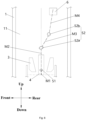
- the image receiving module 6 is disposed at the top of the furnace chamber 11 and extends along the up-down direction, specifically, before the growth of the single crystal, first, the vertical interval between the liquid surface of the melt 21 and the guide cylinder 3 is adjusted to the set value in a manner of lifting and lowering the crucible 2, at the time, the height of the liquid level of the melt 21 is an M position, after the setting of the interval, the image of the detection area received by the image receiving module 6 is marked as a set position (as the M' position shown in Fig. 4 ), according to the reflection principle of light, when the image received by the image receiving module 6 moves upwards relative to the M' position (as the N' position shown in Fig.
- the height position of the liquid surface of the melt 21 in the crucible 2 falls (as the N position shown in Fig. 4 ), that is, the vertical interval between the liquid surface of the melt 21 and the guide cylinder 3 is enlarged, therefore, by controlling the crucible 2 to rise, the crucible 2 is enabled to move in a direction close to the guide cylinder 3, so that the interval between the liquid surface of the melt 21 and the guide cylinder 3 is gradually shortened till meeting the set distance.
- the reflection module further includes: at least one second reflection member 52, the second reflection member 52 is disposed above the first reflection member 51, and reflection light of the first reflection member 51 is suitable for entering the image receiving module 6 after being reflected by the second reflection member 52. It can be understood that reflection light of the first reflection member 51 may be re-reflected through the second reflection member 52, so that the propagation path of light may be re-adjusted flexibly.
- the reflection module may flexibly adjust the reflection direction of the second reflection member 52 according to the position of the image receiving module 6, so that the image receiving module 6 may clearly and completely receive image information of the detection area. For example, when the furnace body 1 is high and the image receiving module 6 is located on the top of the furnace chamber 11, referring to Fig.
- the highest position of the reflection light of the first reflection member 51 may only reach the middle position of the furnace body 1, so that the image receiving module 6 cannot receive the reflection light of the first reflection member 51, therefore, by disposing the second reflection member 52 above the first reflection member 51, the second reflection member 52 may receive and further reflect the reflection light of the first reflection member 51, for example, by adjusting the orientation of the reflection surface of the second reflection member 52, the reflection angle of the second reflection member 52 may be accurately controlled, so that the image receiving module 6 may receive the reflection light of the second reflection member 52, namely, receive the image information of the detection area.
- the image receiving module 6 and the detection area are located on two opposite sides in the radial direction of the crystal rod 4, and the image of the detection area is suitable for entering the image receiving module 6 by bypassing the crystal rod 4 after being reflected by the first reflection member 51 and the second reflection member 52. That is, the second reflection member 52 is suitable for reflecting the reflection light of the first reflection member 51 towards the side, away from the detection area, of the crystal rod 4, so that the image receiving module 6 may receive the image information of the detection area through the reflection module.
- the detection area is located on the right side of the crystal rod 4, and the image receiving module 6 is located on the left side of the crystal rod 4.
- the second reflection member 52 is located outside the guide cylinder 3 and above the guide cylinder 3. Therefore, the mounting difficulty of the second reflection member 52 may be better reduced, thus reducing the difficulty of later angle adjustment or maintenance of the second reflection member 52. Meanwhile, the distance of the first reflection member 51 and the second reflection member 52 in the radial direction of the guide cylinder 3 may be better prolonged, so that reflection light of the second reflection member 52 has a higher projection angle, so as to adapt to image receiving modules 6 of different heights. Meanwhile, the distance of the second reflection member 52 and the liquid surface of the melt 21 may be better prolonged, so as to reduce influence of the high temperature of the melt 21 on the second reflection member 52.
- the second reflection member 52 is disposed on the outer side of the guide cylinder 3, so that the bad influence of position offset of the second reflection member 52 caused by the flow of the inert gas may be avoided, which is beneficial for improving completeness and clarity of the image received by the image receiving module 6.
- a plurality of second reflection members 52 are provided, the plurality of second reflection members 52 are distributed at intervals along the axial direction of the guide cylinder 3, the plurality of second reflection members 52 are distributed at intervals along the up-down direction, and the reflection light of the first reflection member 51 is suitable for entering the image receiving module 6 by bypassing the crystal rod 4 after being reflected by the plurality of second reflection members 52 in sequence. It can be understood that the reflection light of the first reflection member 51 may be reflected for a plurality of times through the plurality of second reflection members 52, so that the propagation path of the light may be adjusted flexibly.
- the image receiving module 6 may clearly and completely receive the image of the detection area, which is beneficial for improving the accuracy of judging the change of position height of the liquid surface of the melt 21.
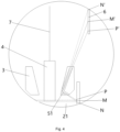
- two second reflection members 52 are provided, the two second reflection members 52 are defined as a primary reflection member 52a and a secondary reflection member 52b, the primary reflection member 52a is located on a right upper side of the first reflection member 51, and the primary reflection member 52a is suitable for obliquely upwards reflecting the reflection light of the first reflection member 51 towards a right rear side; the secondary reflection member 52b is located on an upper side of the primary reflection member 52a, the secondary reflection member 52b is located on the right rear side of the primary reflection member 52a, and the secondary reflection member 52b is suitable for obliquely upwards reflecting a reflection light of the primary reflection member 52a towards a left rear side.
- the reflection module includes one first reflection member 51 and two second reflection members 52 disposed at intervals in the up-down direction, first, the image of the detection area is transmitted to the first reflection member 51 along M1, the lower second reflection member 52 is located at the upper right of the first reflection member 51, and the lower second reflection member 52 is suitable for re-reflecting the reflection light of the first reflection member 51 (M2 as shown in Figs. 5 and 6 ) towards upward of the right rear side (M3 as shown in Figs. 5 and 6 ).
- the upper second reflection member 52 is located at the upper right of the lower second reflection member 52, the upper second reflection member 52 is suitable for re-reflecting the reflection light of the second reflection member 52 (M3 as shown in Figs. 5 and 6 ) towards upward of the left rear side (M4 as shown in Figs. 5 and 6 ), so that image information of the detection area is projected in the image receiving module 6 located at the upper left of the furnace chamber 11.
- the number of the second reflection member 52 may be flexibly set according to the height and other positions of the image receiving module 6, for example, the second reflection member 52 may be one, two, there, and the like, which is not limited herein.
- the reflection surface of the first reflection member 51 faces obliquely upward. Therefore, the reflected light of the first reflection member 51 may be projected to a higher position.
- the guide cylinder 3 has a shorter distance to the liquid surface of the melt 21, so that the first reflection member 51 is close to the liquid surface of the melt 21 in the vertical direction, therefore, by enabling the reflection surface of the first reflection member 51 to face obliquely upward, the first reflection member 51 may reflect the image of the detection area to a higher position, and the propagation path of the reflection light is longer.
- the reflection surface of the second reflection member 52 faces obliquely downwards, so that the second reflection member 52 may receive the reflection light of the first reflection member 51, so as to guarantee completeness of light propagation.
- an observation window (not shown in the figures) for observing the image information of the image receiving module 6 is disposed on the furnace body 1, and the observation window is disposed at the upper end of the furnace body 1. Therefore, through the observation window, the worker may intuitively know the change of the image information on the image receiving module 6, which is convenient for the worker to adjust the interval between the liquid surface of the melt 21 and the guide cylinder 3 in time according to the change of the image information, so as to ensure the growth quality of the single crystal.
- the diameter of the through hole in the center of the guide cylinder 3 is gradually enlarged, the observation window is disposed at the upper end of the furnace body 1, so that the field of view of the observation window is wider, it can better prevent the guide cylinder 3 from blocking the halo area of the single crystal, so that the worker may observe the diameter of the single crystal through the observation window, thereby ensuring that the single crystal grows to meet the size requirement.
- the image receiving module 6 is directly in communication connection with an upper computer, so that the received image information may be directly transmitted to the upper computer, the worker may observe through the upper computer, and the operation difficulty is low.
- the upper computer may, through comparison of the image information and the set image information, judge the current position height of the liquid surface of the melt 21, meanwhile, the upper computer may directly control the rising and lowering of the crucible 2 according to the change of the position height of liquid surface of the melt 21, which is beneficial for improving the automatic level of the single crystal growth device 100.
- annular guide rail (not shown in the figures) is disposed at an inner side of a top wall of the furnace body 1, the annular guide rail defines a sliding groove, a slider (not shown in the figures) is disposed at a top of the image receiving module 6, the slider is embedded in the sliding groove, and the slider is suitable for sliding along an extending direction of the annular guide rail, so as to adjust a relative position of the image receiving module 6 and the reflection module in a circumferential direction of the furnace body 1.
- the relative position of the image receiving module 6 and the reflection module in the circumferential direction of the furnace body 1 may be adjusted, so that the light reflected by the reflection module may be projected on the image receiving module 6, thus guaranteeing the accurate capturing of the reflection image. It is to be noted that after each time of charging of the single crystal growth device 100, position movement of parts possibly exists, in order to the guarantee accurate capturing for the reflection image, the relative position of the image receiving module 6 and the reflection module may be adjusted through the above operation.
- the image receiving module includes: a first sub-receiving module and a second sub-receiving module (not shown in the figures), an accommodating cavity is defined in the first sub-receiving module, an opening is formed at a bottom of the accommodating cavity, the second sub-receiving module is slidably connected with the first sub-receiving module, and the second sub-receiving module is suitable for moving between a first position contained in the accommodating cavity and a second position extending out of the opening, so as to adjust a relative position of the second sub-receiving module and the reflection module in an axial direction of the furnace body 1.
- the relative position of the second sub-receiving module and the reflection module in the axial direction of the furnace body 1 may be adjusted, so that the light reflected by the reflection module may be projected on the image receiving module 6, thus guaranteeing the accurate capturing for the reflection image.
- the relative position of the image receiving module 6 and the reflection module may be more accurately adjusted in the axial and circumferential directions (two dimensions) of the furnace body 1, so as to further ensure the reliability of image capture.
Landscapes
- Chemical & Material Sciences (AREA)
- Engineering & Computer Science (AREA)
- Crystallography & Structural Chemistry (AREA)
- Materials Engineering (AREA)
- Metallurgy (AREA)
- Organic Chemistry (AREA)
- Crystals, And After-Treatments Of Crystals (AREA)
Applications Claiming Priority (2)
| Application Number | Priority Date | Filing Date | Title |
|---|---|---|---|
| CN202210100195.1A CN114606565B (zh) | 2022-01-27 | 2022-01-27 | 单晶生长装置 |
| PCT/CN2022/122625 WO2023142507A1 (fr) | 2022-01-27 | 2022-09-29 | Dispositif de croissance de monocristal |
Publications (4)
| Publication Number | Publication Date |
|---|---|
| EP4471190A1 true EP4471190A1 (fr) | 2024-12-04 |
| EP4471190A4 EP4471190A4 (fr) | 2025-04-30 |
| EP4471190C0 EP4471190C0 (fr) | 2026-02-18 |
| EP4471190B1 EP4471190B1 (fr) | 2026-02-18 |
Family
ID=81860086
Family Applications (1)
| Application Number | Title | Priority Date | Filing Date |
|---|---|---|---|
| EP22923311.9A Active EP4471190B1 (fr) | 2022-01-27 | 2022-09-29 | Dispositif de croissance de monocristal |
Country Status (4)
| Country | Link |
|---|---|
| EP (1) | EP4471190B1 (fr) |
| CN (1) | CN114606565B (fr) |
| TW (1) | TWI805520B (fr) |
| WO (1) | WO2023142507A1 (fr) |
Families Citing this family (2)
| Publication number | Priority date | Publication date | Assignee | Title |
|---|---|---|---|---|
| CN114606565B (zh) * | 2022-01-27 | 2023-01-20 | 徐州鑫晶半导体科技有限公司 | 单晶生长装置 |
| CN115928212A (zh) * | 2022-12-30 | 2023-04-07 | 江苏集芯半导体硅材料研究院有限公司 | 一种内部可视的碳化硅单晶生长装置 |
Family Cites Families (15)
| Publication number | Priority date | Publication date | Assignee | Title |
|---|---|---|---|---|
| JP2735960B2 (ja) * | 1991-04-30 | 1998-04-02 | 三菱マテリアル株式会社 | 液面制御方法 |
| US5286461A (en) * | 1991-09-20 | 1994-02-15 | Ferrofluidics Corporation | Method and apparatus for melt level detection in czochralski crystal growth systems |
| GB9810207D0 (en) * | 1998-05-14 | 1998-07-08 | Secr Defence | Crystal growth apparatus and method |
| TW546423B (en) * | 2000-05-01 | 2003-08-11 | Komatsu Denshi Kinzoku Kk | Method and apparatus for measuring melt level |
| JP4209082B2 (ja) * | 2000-06-20 | 2009-01-14 | コバレントマテリアル株式会社 | 単結晶引上げ装置および引上げ方法 |
| JP5181178B2 (ja) * | 2007-09-12 | 2013-04-10 | Sumco Techxiv株式会社 | 半導体単結晶製造装置における位置計測装置および位置計測方法 |
| KR101028933B1 (ko) * | 2009-01-22 | 2011-04-12 | 주식회사 엘지실트론 | 단결정 멜트 레벨 조절 장치, 이를 구비하는 단결정 성장 장치 및 단결정 멜트 레벨 조절 방법 |
| CN103628131B (zh) * | 2013-12-06 | 2016-05-04 | 西安德伍拓自动化传动系统有限公司 | 一种单晶硅拉晶炉的熔融硅液面检测方法及测量装置 |
| CN104005083B (zh) * | 2014-05-20 | 2016-06-29 | 北京工业大学 | 一种测量单晶炉熔硅液面高度的装置与方法 |
| KR101698540B1 (ko) * | 2015-02-11 | 2017-01-20 | 영남대학교 산학협력단 | 실리콘 잉곳 제조 장치 |
| JP6812931B2 (ja) * | 2017-09-06 | 2021-01-13 | 株式会社Sumco | 液面レベル検出装置の調整用治具および調整方法 |
| JP7272249B2 (ja) * | 2019-12-02 | 2023-05-12 | 株式会社Sumco | 単結晶育成方法および単結晶育成装置 |
| CN112725884A (zh) * | 2020-12-21 | 2021-04-30 | 江苏集芯半导体硅材料研究院有限公司 | 一种用于检测直拉单晶生长过程中熔硅液面距离的装置及方法 |
| CN214992008U (zh) * | 2021-04-27 | 2021-12-03 | 西安奕斯伟硅片技术有限公司 | 测量拉晶炉熔硅液面高度的结构及拉晶炉 |
| CN114606565B (zh) * | 2022-01-27 | 2023-01-20 | 徐州鑫晶半导体科技有限公司 | 单晶生长装置 |
-
2022
- 2022-01-27 CN CN202210100195.1A patent/CN114606565B/zh active Active
- 2022-09-29 WO PCT/CN2022/122625 patent/WO2023142507A1/fr not_active Ceased
- 2022-09-29 EP EP22923311.9A patent/EP4471190B1/fr active Active
- 2022-11-08 TW TW111142521A patent/TWI805520B/zh active
Also Published As
| Publication number | Publication date |
|---|---|
| TW202311572A (zh) | 2023-03-16 |
| CN114606565B (zh) | 2023-01-20 |
| TWI805520B (zh) | 2023-06-11 |
| CN114606565A (zh) | 2022-06-10 |
| EP4471190C0 (fr) | 2026-02-18 |
| WO2023142507A1 (fr) | 2023-08-03 |
| EP4471190A4 (fr) | 2025-04-30 |
| EP4471190B1 (fr) | 2026-02-18 |
Similar Documents
| Publication | Publication Date | Title |
|---|---|---|
| EP4471190A1 (fr) | Dispositif de croissance de monocristal | |
| JP5708171B2 (ja) | シリコン単結晶引き上げ装置及びシリコン単結晶の製造方法 | |
| US5922127A (en) | Heat shield for crystal puller | |
| US20230357949A1 (en) | Ingot Growth Device and Growth Method | |
| EP2971275B1 (fr) | Ensemble creuset destiné à réguler l'oxygène et procédés associés | |
| KR20020081287A (ko) | 성장 속도 및 직경 편차를 최소화하도록 실리콘 결정의성장을 제어하는 방법 | |
| KR20000069103A (ko) | 단결정 인양장치 | |
| WO2023124334A1 (fr) | Dispositif de réglage de champ thermique et procédé de croissance de monocristal | |
| US20200115821A1 (en) | Method for producing silicon single crystal, heat shield, and single crystal pulling device | |
| CN1936108A (zh) | 高质量硅单晶结晶块的生长装置及使用此装置的生长方法 | |
| US12065757B2 (en) | Monocrystal growth method and monocrystal growth device | |
| JP6889170B2 (ja) | 単結晶の引上げの間に単結晶の直径を決定および調節するための方法 | |
| CN214060710U (zh) | 晶体生长装置的控制系统和晶体生长装置 | |
| LU507230B1 (en) | Single crystal growth device | |
| CN110129879A (zh) | 一种双副室单晶硅筒生长炉及单晶硅生长方法 | |
| CN214142610U (zh) | 一种用于拉制单晶硅棒的拉晶炉 | |
| JP4844127B2 (ja) | 単結晶製造装置および製造方法 | |
| KR101699834B1 (ko) | 실리콘 단결정 잉곳 성장장치 | |
| CN210856408U (zh) | 一种设置有炉体升降机构的晶体生长炉 | |
| KR102271787B1 (ko) | Fz법에 의한 단결정 인상을 위한 방법 및 플랜트 | |
| JP7746946B2 (ja) | 単結晶製造装置 | |
| KR20230028564A (ko) | 단결정 성장용 열장 조절 장치 및 방법 | |
| CN221028761U (zh) | 晶体生长装置 | |
| CN219526863U (zh) | 浮区法晶体生长炉 | |
| US11377752B2 (en) | Mono-crystalline silicon growth method |
Legal Events
| Date | Code | Title | Description |
|---|---|---|---|
| STAA | Information on the status of an ep patent application or granted ep patent |
Free format text: STATUS: THE INTERNATIONAL PUBLICATION HAS BEEN MADE |
|
| PUAI | Public reference made under article 153(3) epc to a published international application that has entered the european phase |
Free format text: ORIGINAL CODE: 0009012 |
|
| STAA | Information on the status of an ep patent application or granted ep patent |
Free format text: STATUS: REQUEST FOR EXAMINATION WAS MADE |
|
| 17P | Request for examination filed |
Effective date: 20240820 |
|
| AK | Designated contracting states |
Kind code of ref document: A1 Designated state(s): AL AT BE BG CH CY CZ DE DK EE ES FI FR GB GR HR HU IE IS IT LI LT LU LV MC MK MT NL NO PL PT RO RS SE SI SK SM TR |
|
| REG | Reference to a national code |
Free format text: PREVIOUS MAIN CLASS: C30B0015000000 Ipc: C30B0015200000 Ref country code: DE Ref legal event code: R079 Ref document number: 602022030888 Country of ref document: DE |
|
| A4 | Supplementary search report drawn up and despatched |
Effective date: 20250328 |
|
| DAV | Request for validation of the european patent (deleted) | ||
| DAX | Request for extension of the european patent (deleted) | ||
| RIC1 | Information provided on ipc code assigned before grant |
Ipc: C30B 29/06 20060101ALN20250324BHEP Ipc: C30B 27/02 20060101ALI20250324BHEP Ipc: C30B 15/30 20060101ALI20250324BHEP Ipc: C30B 15/20 20060101AFI20250324BHEP |
|
| GRAP | Despatch of communication of intention to grant a patent |
Free format text: ORIGINAL CODE: EPIDOSNIGR1 |
|
| STAA | Information on the status of an ep patent application or granted ep patent |
Free format text: STATUS: GRANT OF PATENT IS INTENDED |
|
| RIC1 | Information provided on ipc code assigned before grant |
Ipc: C30B 15/20 20060101AFI20250925BHEP Ipc: C30B 15/30 20060101ALI20250925BHEP Ipc: C30B 27/02 20060101ALI20250925BHEP Ipc: C30B 29/06 20060101ALN20250925BHEP |
|
| INTG | Intention to grant announced |
Effective date: 20251022 |
|
| GRAS | Grant fee paid |
Free format text: ORIGINAL CODE: EPIDOSNIGR3 |
|
| GRAA | (expected) grant |
Free format text: ORIGINAL CODE: 0009210 |
|
| STAA | Information on the status of an ep patent application or granted ep patent |
Free format text: STATUS: THE PATENT HAS BEEN GRANTED |
|
| AK | Designated contracting states |
Kind code of ref document: B1 Designated state(s): AL AT BE BG CH CY CZ DE DK EE ES FI FR GB GR HR HU IE IS IT LI LT LU LV MC MK MT NL NO PL PT RO RS SE SI SK SM TR |
|
| REG | Reference to a national code |
Ref country code: CH Ref legal event code: F10 Free format text: ST27 STATUS EVENT CODE: U-0-0-F10-F00 (AS PROVIDED BY THE NATIONAL OFFICE) Effective date: 20260218 Ref country code: GB Ref legal event code: FG4D |
|
| REG | Reference to a national code |
Ref country code: IE Ref legal event code: FG4D |
|
| REG | Reference to a national code |
Ref country code: DE Ref legal event code: R096 Ref document number: 602022030888 Country of ref document: DE |
|
| REG | Reference to a national code |
Ref country code: CH Ref legal event code: R17 Free format text: ST27 STATUS EVENT CODE: U-0-0-R10-R17 (AS PROVIDED BY THE NATIONAL OFFICE) Effective date: 20260320 |
|
| U01 | Request for unitary effect filed |
Effective date: 20260304 |
|
| U07 | Unitary effect registered |
Designated state(s): AT BE BG DE DK EE FI FR IT LT LU LV MT NL PT RO SE SI Effective date: 20260310 |