EP4471349A1 - Vorrichtung zur thermodynamischen erwärmung eines flüssigkeitsbehälters und entsprechendes verlegeverfahren - Google Patents
Vorrichtung zur thermodynamischen erwärmung eines flüssigkeitsbehälters und entsprechendes verlegeverfahren Download PDFInfo
- Publication number
- EP4471349A1 EP4471349A1 EP24179408.0A EP24179408A EP4471349A1 EP 4471349 A1 EP4471349 A1 EP 4471349A1 EP 24179408 A EP24179408 A EP 24179408A EP 4471349 A1 EP4471349 A1 EP 4471349A1
- Authority
- EP
- European Patent Office
- Prior art keywords
- tank
- tube
- coil
- shaped
- condenser
- Prior art date
- Legal status (The legal status is an assumption and is not a legal conclusion. Google has not performed a legal analysis and makes no representation as to the accuracy of the status listed.)
- Pending
Links
Images


Classifications
-
- F—MECHANICAL ENGINEERING; LIGHTING; HEATING; WEAPONS; BLASTING
- F24—HEATING; RANGES; VENTILATING
- F24H—FLUID HEATERS, e.g. WATER OR AIR HEATERS, HAVING HEAT-GENERATING MEANS, e.g. HEAT PUMPS, IN GENERAL
- F24H4/00—Fluid heaters characterised by the use of heat pumps
- F24H4/02—Water heaters
- F24H4/04—Storage heaters
-
- F—MECHANICAL ENGINEERING; LIGHTING; HEATING; WEAPONS; BLASTING
- F25—REFRIGERATION OR COOLING; COMBINED HEATING AND REFRIGERATION SYSTEMS; HEAT PUMP SYSTEMS; MANUFACTURE OR STORAGE OF ICE; LIQUEFACTION SOLIDIFICATION OF GASES
- F25B—REFRIGERATION MACHINES, PLANTS OR SYSTEMS; COMBINED HEATING AND REFRIGERATION SYSTEMS; HEAT PUMP SYSTEMS
- F25B39/00—Evaporators; Condensers
- F25B39/04—Condensers
-
- F—MECHANICAL ENGINEERING; LIGHTING; HEATING; WEAPONS; BLASTING
- F28—HEAT EXCHANGE IN GENERAL
- F28D—HEAT-EXCHANGE APPARATUS, NOT PROVIDED FOR IN ANOTHER SUBCLASS, IN WHICH THE HEAT-EXCHANGE MEDIA DO NOT COME INTO DIRECT CONTACT
- F28D1/00—Heat-exchange apparatus having stationary conduit assemblies for one heat-exchange medium only, the media being in contact with different sides of the conduit wall, in which the other heat-exchange medium is a large body of fluid, e.g. domestic or motor car radiators
- F28D1/06—Heat-exchange apparatus having stationary conduit assemblies for one heat-exchange medium only, the media being in contact with different sides of the conduit wall, in which the other heat-exchange medium is a large body of fluid, e.g. domestic or motor car radiators with the heat-exchange conduits forming part of, or being attached to, the tank containing the body of fluid
-
- F—MECHANICAL ENGINEERING; LIGHTING; HEATING; WEAPONS; BLASTING
- F28—HEAT EXCHANGE IN GENERAL
- F28D—HEAT-EXCHANGE APPARATUS, NOT PROVIDED FOR IN ANOTHER SUBCLASS, IN WHICH THE HEAT-EXCHANGE MEDIA DO NOT COME INTO DIRECT CONTACT
- F28D20/00—Heat storage plants or apparatus in general; Regenerative heat-exchange apparatus not covered by groups F28D17/00 or F28D19/00
- F28D20/0034—Heat storage plants or apparatus in general; Regenerative heat-exchange apparatus not covered by groups F28D17/00 or F28D19/00 using liquid heat storage material
-
- F—MECHANICAL ENGINEERING; LIGHTING; HEATING; WEAPONS; BLASTING
- F24—HEATING; RANGES; VENTILATING
- F24D—DOMESTIC- OR SPACE-HEATING SYSTEMS, e.g. CENTRAL HEATING SYSTEMS; DOMESTIC HOT-WATER SUPPLY SYSTEMS; ELEMENTS OR COMPONENTS THEREFOR
- F24D2220/00—Components of central heating installations excluding heat sources
- F24D2220/06—Heat exchangers
-
- F—MECHANICAL ENGINEERING; LIGHTING; HEATING; WEAPONS; BLASTING
- F28—HEAT EXCHANGE IN GENERAL
- F28D—HEAT-EXCHANGE APPARATUS, NOT PROVIDED FOR IN ANOTHER SUBCLASS, IN WHICH THE HEAT-EXCHANGE MEDIA DO NOT COME INTO DIRECT CONTACT
- F28D20/00—Heat storage plants or apparatus in general; Regenerative heat-exchange apparatus not covered by groups F28D17/00 or F28D19/00
- F28D2020/0065—Details, e.g. particular heat storage tanks, auxiliary members within tanks
- F28D2020/0078—Heat exchanger arrangements
Definitions
- the present invention relates generally to thermodynamic liquid tank heating apparatus, such as thermodynamic water heaters.
- thermodynamic heating devices which are used to heat a tank filled with liquid, for example water.
- These devices include a heat pump system containing a refrigerant.
- a condenser Around the tank is a part of the refrigeration circuit, called a condenser, which heats the liquid in the tank.
- the fluid condenses in the circuit around the tank in order to heat the liquid in the tank by heat transfer.
- Thermal paste may be present between the condenser and the tank in order to optimize heat exchanges.
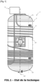
- thermodynamic water heater condenser which is formed by a tube placed by manual or semi-automatic spiral winding around the tank as illustrated in the Figure 1 .
- thermodynamic water heater 1' comprises a tank 2 and a condenser 3' which comprises a tube wound in turns around the peripheral wall 20 of the tank 2.
- belt-shaped condensers such as belts with micro-channels or so-called “roll bond” belts.
- the extruded aluminum tubes are welded together on vertical collectors. Welding the tubes to the collectors increases the risk of refrigerant leakage. Furthermore, the welding process requires the installation of specific ovens and the manual installation of the tubes on the collector, reducing the repeatability of the manufacturing process. Finally, the volume of the collectors increases the amount of refrigerant used, without the refrigerant present in the collector participating in the heat exchange between the tank and the condenser.
- roll-bond belts are made by a cold welding process by rolling two metal sheets and then pressurizing to form the circuit.
- These roll-bond belts are difficult to manufacture because the material used may not withstand the forming pressure and it is difficult to design a circuit that is sufficiently resistant to the operating pressure.
- this type of belt requires good cylindricity and a good surface condition of the tank, which is difficult to obtain, to ensure good contact and good heat exchange between the belt and the tank.
- the rigidity of the panel formed by the metal sheets makes it difficult to apply it around the tank, so that there is a risk of degradation of the condenser and a loss of performance.
- the aim of the present invention is to propose a new thermodynamic heating device and a corresponding condenser installation method making it possible to at least partially overcome all or part of the problems set out above.
- thermodynamic heating device for this purpose, the invention relates to a thermodynamic heating device according to claim 1.
- Such a conformation of the extruded tube - which in flat configuration is in the form of a serpentine - makes it possible to automatically apply this serpentine against the peripheral wall of the tank and to press this serpentine against the tank at the same time as the latter rotates one turn on itself to encircle the tank with the serpentine.
- This operation of installing the condenser on the tank can be carried out on a production line of the device, that is to say in the cycle time of the production line, preferably less than 45 seconds, without having to temporarily store the tank outside the production line to carry out the application of the condenser on the tank.
- each winding element extends around a part of the circumference of the tank, around the longitudinal axis of the tank (and likewise for the second portion) being followed by an internal U-shaped return, and that this internal U-shaped return of each winding element extends in a plane orthogonal to the plane in which the first or second tube portion extends, makes it possible to obtain a configuration of the condenser thanks to which the heat exchanges between the condenser and the tank are improved and this in a simple manner.
- such a configuration of the condenser allows the refrigerant fluid to travel around the upper part of the tank over a long winding distance before reaching the lower part of the tank, which allows generating a stratification of the water, so as to have hot water. in the upper part at the level from which the water is drawn while the (cold) water inlet is located at the bottom in a water heater.
- the heating appliance such as a thermodynamic water heater, may also include one or more of the following characteristics taken in any technically admissible combination.
- the condenser tube through which the refrigerant is intended to circulate is made of a single piece without connecting several sections of tubes.
- the winding elements and the U-shaped connecting returns are formed by a single tube without connection, such as welding, which is shaped to obtain, when flat, a serpentine which, in the state applied against the tank, forms the winding elements and the connecting returns between the winding elements.
- the inlet is formed by a straight tube portion which extends parallel to the longitudinal axis of the tank, and which is extended by the first winding element.
- the outlet is formed by another straight portion of the tube which extends parallel to the longitudinal axis while being further away from the longitudinal axis than the inlet.
- the extruded tube is made of aluminum or copper.
- the tube has a circular or D-shaped section.
- the internal U-shaped return of each winding element extends in a plane orthogonal to the plane in which the first or second tube portion extends.
- the winding elements and the connecting returns form, in flat configuration, a coil, called the main coil, which, in the state applied against the peripheral wall of the tank, forms a belt, one end of which is formed by the connecting returns located on one side. same first side of the coil, and whose opposite end is formed by the returns located on the same second side of the coil, opposite the first side.
- the curved extruded tube of the condenser also comprises an additional coil, the straight parts of which are, in the flat configuration of the tube, orthogonal to the straight parts of the main coil, the additional coil being arranged between the outlet and the main coil, and being applicable to the bottom wall of the tank considered in a vertical position in the configuration of use of the tank.
- thermodynamic heating apparatus comprises a holding system configured to keep said portions of the winding elements of the tube spaced apart from each other so as to maintain the shape of the belt.
- the thermodynamic heating apparatus comprises clamping means for bringing the ends of the belt formed by the curved extruded tube towards each other, to clamp the belt against the tank.
- the clamping means are fixed to the holding system.
- the clamping means comprise hooks and springs.
- each of the first and second portions of each winding element develops along an arc of a circle around the longitudinal axis of the tank.
- the diameter of each of said arcs of a circle is greater than the radius of curvature of the U-shaped return.
- each of the first and second portions of each winding element is of a length greater than the length of the U-shaped return which connects them.
- each of the first and second portions of at least part of the, preferably each, winding elements extends around the longitudinal axis over a circular arc of more than 180°, preferably over a circular arc of more than 270°, advantageously of more than 330°.
- At least one part, preferably each of the first and second portions, is of a length greater than the U-shaped return which connects them.
- the length of each of the first and second portions of each winding element is greater than the cumulative length of the U-shaped returns of the winding elements.
- each of the first and second portions of each winding element develops in a plane transverse to the longitudinal axis of the tank.
- the first and second portions of each winding element extend in planes parallel to each other.
- the first and second portions of each winding element extend in planes parallel to the planes in which the first and second portions of each other winding element extend.
- the tank comprising a water inlet in the lower part of the tank and a water draw-off zone in the upper part of the tank, the winding element closest to the refrigerant inlet relative to the other winding elements is located in the upper part of the tank (in other words, on the side of the water draw-off zone of the tank).
- the refrigerant thus flows through the winding elements from top to bottom, first heating the upper part of the tank.
- the physical hot water outlet of the tank (corresponding to a zone for connecting the tank to a domestic hot water circuit) may be located like said water draw-off zone in the upper part of the tank or be positioned in the lower part (bottom) of the tank, being connected by a tube to said water draw-off zone in the upper part of the tank.
- the winding element closest to the refrigerant outlet is located in the lower part of the tank (in other words, on the side of the cold water inlet).
- the distance between the refrigerant inlet and a winding element, as well as the distance between a winding element and the refrigerant outlet, means the distance that the refrigerant must travel between said winding element and said refrigerant inlet or outlet.
- the invention also relates to a method for automatically installing a curved extruded condenser tube on a tank of a thermodynamic heating appliance, the method being in accordance with claim 15.
- thermodynamic heating device as proposed above.
- the coil has portions of different sections, said portions of the coil being obtained for example by end-to-end assembly of several portions of tube of different sections or by deformation of portions of the coil.
- a tank 2 of a thermodynamic heating appliance contains liquid, for example water, which is intended to be heated by a refrigeration circuit of a heat pump system (HP) of the appliance which will be described later.
- HP heat pump system
- the appliance is a water heater.
- thermodynamic heating appliance comprising a liquid tank.
- the tank 2 filled with water extends along a longitudinal dimension which, here, is taken along the vertical axis since the tank is arranged vertically.
- a tank arranged horizontally (horizontal longitudinal dimension) or inclined also applies to a tank arranged horizontally (horizontal longitudinal dimension) or inclined.
- the tank comprises a wall 20 which is here generally cylindrical and is closed at its two opposite ends by two bottoms or caps and substantially elliptical.
- the tank 2 has a peripheral wall 20 which extends around a longitudinal axis A2.
- the tank 2 also has a bottom wall 22 which forms the bottom of the tank and which extends the peripheral wall 20 in the lower part of the tank.
- the tank also has a top wall 21 which forms the top of the tank and which extends the peripheral wall in the upper part of the tank.
- the water heater also includes a heat pump system 6 which includes a refrigeration circuit, a part of which is applied to the tank 2 and which contains a refrigerant fluid, for example r134a.
- the part of the refrigeration circuit which is applied around the tank forms the condenser of the circuit.
- the condenser 3 according to the invention, examples of which are illustrated in Figures 2 And 4 , is distinguished from the 3' condenser of the Figure 1 known from the state of the art because, in the Figure 1 , the condenser 3' is formed by a spiral winding around the tank, whereas in the invention and as illustrated for example in the Figure 2 and to the Figure 4 , the condenser 3 presents - in flat configuration and as visible in the Figure 4 - a serpentine shape 38, which is applied laterally against the tank 2 in the manner of a belt, as illustrated in Figure 2 .
- the condenser 3 comprises an extruded tube which forms a refrigerant circulation circuit which comprises an inlet 301 and an outlet 399.
- the tube is for example made of aluminum or copper.
- the application of the condenser 3 according to the invention on the tank 2 requires only a single rotation of the tank around its axis A2 to laterally press the serpentine shape (presented below) according to which a part of the tube is shaped, and thus surround the tank, whereas the production of the spiral winding of the condenser 3' of the Figure 1 around the tank requires as many rotations of the tank as there are turns.
- thermodynamic water heater 1 of simple and reliable design is thus proposed, the condenser 3 of which comprises an extruded refrigerant circulation tube which is curved so that at least part of the tube is shaped into a coil 38, which is flat before application to the tank, which makes it possible to easily apply the flat shape of this coil 38 of the condenser to the peripheral wall of the tank 2 of the water heater, in particular on a water heater production line.
- the condenser tube which contains the refrigerant is in thermal contact with the external face of the wall of the tank.
- the condenser tube 3 comprises straight parts 310, 312, 320, 322, 330, 332 connected between them by bends 311, 321, 331, 313, 323, 333 (U-shaped return) with alternating direction of concavity from one bend to another.
- a given bend is obtained by bending the tube in one direction
- the next bend is obtained by bending the tube in the other direction.
- the condenser tube thus bent forms said coil 38, called the main coil, which comprises straight parts parallel to each other and bends between these straight parts.
- the condenser inlet communicates with one end of the coil and the condenser outlet communicates with the other end of the coil.
- the winding elements 31, 32, 33 are connected to each other by elbows or returns 313, 323, 333, called connecting elbows or returns curved in the opposite direction to the internal elbows or returns of the winding elements.
- the coil 38 may have portions of different sections. Said portions of the coil 38 may be obtained by end-to-end assembly of several portions of tube of different sections or by deformation of portions of the coil.
- the tube of the condenser 3 also comprises an additional coil 39, the straight parts of which are, in flat configuration, orthogonal to the straight parts of the main coil 38.
- the additional coil 39 is arranged between the outlet 399 and the main coil 38, and can be applied to the bottom wall 22 of the tank 2 considered in a vertical position in the configuration of use of the water heater.
- the additional coil 39 is connected by a part 340, 333 of the tube to the main coil 38 formed by the winding elements 31, 32, 33.
- the tube of the condenser 3 comprises a first winding element 31 which comprises a first portion 310 extending around at least part of the circumference of the tank (around the longitudinal axis A2 of the tank 2), followed by a U-shaped return 311 (elbow).
- the U-shaped return 311 is such that the bending axis A311 around which the tube is bent to obtain the U-shaped return (i.e. the axis of the through opening defined by the elbow - U-shaped return) is transverse, preferably orthogonal, to the longitudinal axis A2 of the tank 2.
- the U-shaped return 311 extends in a plane orthogonal to the plane in which the first portion 310 extends around the tank.
- the bending axis of the U-shaped return i.e. the axis of the through opening defined between the two branches of the U is orthogonal to said plane in which the tube extends before application to the tank.
- the U-shaped return 311 is extended by a second portion 312 which develops parallel to the first portion 311, around at least part of the circumference of the tank 2, in the opposite direction to the first portion 310 (for reference a direction of travel of the tube from the inlet towards the outlet of the tube).
- the condenser 3 comprises several winding elements 32, 33 produced like the winding part 31, and which are connected to each other by U-shaped returns.
- each connecting return 313 between two winding elements 31, 32 is such that the bending axis A313 around which the tube is bent to obtain the U-shaped return (i.e. the axis of the through opening defined by the elbow - U-shaped return) is transverse, preferably orthogonal, to the longitudinal axis A2 of the tank.
- each U-shaped connecting return extends in a plane orthogonal to the plane in which each of the portions 312, 320 of winding elements 31, 32 that are connected to each other by said connecting return 313 develops.
- the bending axis A313 of a U-shaped connection return 313, i.e. the axis of the through opening defined between the two branches of the U, is orthogonal to said plane in which the tube extends before application to the tank.
- the winding elements and the U-shaped connecting returns are formed from a single extruded tube.
- the condenser tube that extends around the tank and through which a refrigerant fluid is intended to circulate is a single tube without any connection such as welding, which is shaped to obtain at least the coil that forms the winding elements and the connecting returns between the winding elements.
- the U-shaped connections may be different from each other, for example to generate a variable spacing.
- the inlet 301 may be formed by a straight tube portion extended by the first winding element.
- the first winding element 310 which extends the inlet 301 is located in the upper part of the tank.
- the tank has a water draw-off zone which is also located in the upper part of the tank while the cold water inlet (arrival) is located in the lower part.
- the drawn water may exit through a water outlet which may be located in the upper part of the tank like the draw-off zone or which may be located in the lower part of the tank by being connected to the draw-off zone by a tube.
- the tank is thus configured so that the hot water present in the tank is drawn from the upper part of the tank while cold water enters in the lower part.
- the refrigerant can thus circulate in the condenser tube from the first winding element 310 located in the upper part of the tank, descending towards the lower part of the tank through the other winding elements 312, 320, 322, located below each other.
- Such a design makes it possible to obtain efficient heat exchanges between the condenser fluid which first passes through the winding elements located in the upper part of the tank and the upper part of the tank where the water to be heated is located which is intended to be taken during use of the water heater.
- Such an arrangement of the condenser makes it possible to obtain and maintain a stratification of the water in the tank with hotter water in the upper part than in the lower part, which makes it possible to reliably and efficiently obtain hot water at the outlet of the tank since the water used at the outlet is taken from the upper part of the tank.
- the water outlet of the tank is intended to be connected to a domestic hot water (DHW) circuit.
- DHW domestic hot water
- the outlet 399 may be formed by a straight portion of tube which extends the last winding element or the remaining portion 39 of the tube which extends between the last winding element and the outlet 399.
- the outlet 399 extends upwards (considering the direction of fluid circulation in the water heater usage configuration).
- the remaining portion 39 of the tube may comprise a portion of an additional winding element, which has only a first winding portion as in the example of the Figure 2 , and/or a portion of a corrugated or serpentine tube intended to come around and/or against the external face of the lower bottom of the tank (i.e. the lower wall of the tank).
- the outlet 399 extends substantially parallel to the inlet 301.
- the outlet 399 which rises from the last winding element, or the remaining portion of the tube which extends between the last winding element and the outlet 399, preferably extends at a distance from the winding elements of the tube to avoid heat exchanges between the winding elements and said outlet.
- the extruded tube is also shaped to form the inlet and outlet, which are preferably in the form of straight portions, and to form the possible remaining portion 39 between the outlet and the winding elements.
- the tube with which the condenser is formed is produced by connection, for example welding of several parts together. It can thus be provided that different parts of the condenser tube are formed separately and then connected together, while having a part which, in the flat state, forms a serpentine while being deformable to be applicable around the peripheral wall of the tank in the manner of a belt and possibly on the lower part of the tank.
- the condenser tube may have a circular or elongated section with a flat part, for example D-shaped.
- the section may vary along the tube.
- the tube shaped so that the winding elements 31, 32, 33 form - in flat configuration - a serpentine 38 can be used as a belt, one end of which is formed by the returns 311, 321, 331 (or elbows) located on the same first side of the serpentine, and the opposite end of which is formed by the returns 313, 323, 333 (or elbows) located on the same second side of the serpentine, opposite the first side.
- the initially flat belt formed by the bent extruded tube can then be applied and deformed (bent) against the tank to come against and around the peripheral wall of the tank so as to encircle it.
- an additional part of the condenser which extends the main coil and which forms an additional coil can come against the lower part of the tank.
- a fastening system 4 is preferably provided to allow the ends of the belt to be brought together or interlocked, which are formed, on the one hand, by the connecting elbows 313, 323 which connect the winding elements. 31, 32, 33 between them and, on the other hand, by the internal elbows 311, 321, 331 of each winding element 31, 32, 33.
- the fastening system 4 makes it possible to tighten the belt formed by the condenser tube 3 against the tank 2.
- the fastening system 4 acts on the condenser tube 3 in the direction of reducing the diameter of the winding elements around the tank to enable them to come as close as possible to the peripheral wall of the tank, preferably to press them against the tank.
- the attachment system 4 comprises, for example, attachment devices each comprising two hooks connected together by a spring. One of the hooks is attached to one end of the belt and the other to the other end of the belt.
- the belt formed by the main coil 38 of the tank can be mechanically tensioned around the tank by other clamping elements, such as clamps.
- the belt it is possible to provide for the belt to be fixed around the tank by welding, or by screwing if necessary.
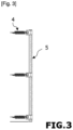
- the condenser tube 3 is provided with a spacing holding device 5 which is fixed to the condenser tube 3 and which is configured to hold apart from each other the portions 310, 312, 320, 322, 330 of the winding elements 31, 32, 33, which are straight in the flat state of the bent tube, and which extend parallel to each other.
- the spacing support device 5 may comprise bars which form uprights extending orthogonally to the straight portions of the condenser winding elements. These uprights of the spacing support device 5 may be hollow but are not traversed by a refrigerant fluid.
- the spacing holding device 5 may comprise fixing elements assembled to the condenser tube by clipping, welding, friction, etc.
- the holding system may also comprise an adhesive film, an aluminum sheet or a net.
- the attachment system 4 can be attached to the spacing holding device 5.
- the invention thus makes it possible to obtain a condenser by deformation (bending) of an extruded tube to obtain at least one part which has a flat serpentine shape with the aim of placing the condenser around the tank by lateral supply of the condenser serpentine and pressing it against the peripheral wall of the tank in order, with a single rotation of the tank, to surround the tank with the condenser (unlike the solution of the technique where a spiral winding of a tube around the tank would require as many rotations of the tank as there are turns to be made).
- the condenser tube can be preformed as explained above to present - in flat configuration - a main serpentine part - which makes it possible to apply one face of the serpentine against the peripheral wall of the tank and to make the opposite lateral parts of this serpentine defined by the sets of elbows curved in opposite directions meet or come closer together, by application of the condenser against the tank, so as to surround the tank with the condenser.
- Such an operation of applying the preformed condenser tube can be carried out in production flow, at the rate of the water heater production line.
- the same tube reference can be used to flat preform different sizes of condenser coil depending on the size or shape of the tanks to be equipped with the condenser.
Landscapes
- Engineering & Computer Science (AREA)
- Physics & Mathematics (AREA)
- Mechanical Engineering (AREA)
- Thermal Sciences (AREA)
- General Engineering & Computer Science (AREA)
- Chemical & Material Sciences (AREA)
- Combustion & Propulsion (AREA)
- Heat-Exchange Devices With Radiators And Conduit Assemblies (AREA)
- Air-Conditioning For Vehicles (AREA)
Applications Claiming Priority (1)
| Application Number | Priority Date | Filing Date | Title |
|---|---|---|---|
| FR2305541A FR3149367B1 (fr) | 2023-06-02 | 2023-06-02 | Appareil de chauffage thermodynamique d’une cuve de liquide et procédés de fabrication et de pose correspondant |
Publications (1)
| Publication Number | Publication Date |
|---|---|
| EP4471349A1 true EP4471349A1 (de) | 2024-12-04 |
Family
ID=87889520
Family Applications (1)
| Application Number | Title | Priority Date | Filing Date |
|---|---|---|---|
| EP24179408.0A Pending EP4471349A1 (de) | 2023-06-02 | 2024-05-31 | Vorrichtung zur thermodynamischen erwärmung eines flüssigkeitsbehälters und entsprechendes verlegeverfahren |
Country Status (2)
| Country | Link |
|---|---|
| EP (1) | EP4471349A1 (de) |
| FR (1) | FR3149367B1 (de) |
Citations (4)
| Publication number | Priority date | Publication date | Assignee | Title |
|---|---|---|---|---|
| CN106940087A (zh) * | 2016-01-04 | 2017-07-11 | 艾欧史密斯(中国)热水器有限公司 | 热泵热水器及水箱 |
| FR3077622A1 (fr) | 2018-02-07 | 2019-08-09 | Atlantic Industrie | Appareil de chauffage thermodynamique d'une cuve |
| CN210128509U (zh) * | 2019-04-10 | 2020-03-06 | 青岛经济技术开发区海尔热水器有限公司 | 一种热水器水箱 |
| CN219607781U (zh) * | 2023-01-19 | 2023-08-29 | 浙江盾安热工科技有限公司 | 换热器及热泵热水器 |
-
2023
- 2023-06-02 FR FR2305541A patent/FR3149367B1/fr active Active
-
2024
- 2024-05-31 EP EP24179408.0A patent/EP4471349A1/de active Pending
Patent Citations (4)
| Publication number | Priority date | Publication date | Assignee | Title |
|---|---|---|---|---|
| CN106940087A (zh) * | 2016-01-04 | 2017-07-11 | 艾欧史密斯(中国)热水器有限公司 | 热泵热水器及水箱 |
| FR3077622A1 (fr) | 2018-02-07 | 2019-08-09 | Atlantic Industrie | Appareil de chauffage thermodynamique d'une cuve |
| CN210128509U (zh) * | 2019-04-10 | 2020-03-06 | 青岛经济技术开发区海尔热水器有限公司 | 一种热水器水箱 |
| CN219607781U (zh) * | 2023-01-19 | 2023-08-29 | 浙江盾安热工科技有限公司 | 换热器及热泵热水器 |
Also Published As
| Publication number | Publication date |
|---|---|
| FR3149367A1 (fr) | 2024-12-06 |
| FR3149367B1 (fr) | 2026-02-20 |
Similar Documents
| Publication | Publication Date | Title |
|---|---|---|
| FR2681421A1 (fr) | Collecteur de raccordement pour un echangeur de chaleur, notamment pour un condenseur de refrigerant. | |
| FR2574175A1 (fr) | Echangeur de chaleur en aluminium | |
| FR2754595A1 (fr) | Echangeur de chaleur, et faisceau d'echange de chaleur, ainsi que procedes de soudage et de realisation s'y rapportant | |
| EP0514248B1 (de) | Wärmeaustauscher mit rohrförmigen Endkammern mit Querwänden und Methode zu seiner Herstellung | |
| WO2012168352A1 (fr) | Reacteur solide / gaz caloporteur et reactif comprenant un conduit helicoïdal dans lequel le solide et le gaz circulent a contre-courant | |
| FR3009862A1 (fr) | Echangeur de chaleur entre deux fluides, utilisation de l'echangeur avec du metal liquide et du gaz, application a un reacteur nucleaire a neutrons rapides refroidi avec du metal liquide | |
| FR3015016A1 (fr) | Boite collectrice et echangeur thermique correspondant | |
| FR2838509A1 (fr) | Echangeur de chaleur a plaques presentant des passages de fluide en saillie | |
| EP4471349A1 (de) | Vorrichtung zur thermodynamischen erwärmung eines flüssigkeitsbehälters und entsprechendes verlegeverfahren | |
| EP3524914B1 (de) | Thermodynamisches heizgerät mit optimiertem mikrokanalkondensator für eine minimale beladung mit kühlflüssigkeit | |
| FR2551193A1 (fr) | Tube de chauffage a garniture en fil metallique anguleuse | |
| EP3295108A1 (de) | In zwei teilen gegossener wärmetauscher und verfahren zur herstellung solch eines wärmetauschers | |
| EP0148695B1 (de) | Solarwassererhitzer mit direktem Wasserdurchgang und Verfahren zu seiner Herstellung | |
| FR2542860A1 (fr) | Echangeur de chaleur a faisceau tubulaire enveloppe et procede d'assemblage dudit echangeur | |
| WO2020234214A1 (fr) | Echangeur de chaleur et système d'échange thermique associé pour véhicule | |
| FR2925374A1 (fr) | Procede de soudure d'elements tubulaires pour radiateur a fluide caloporteur et radiateur ainsi realise | |
| FR2793875A1 (fr) | Echangeur thermique a plaques | |
| BE1026824B1 (fr) | Corps d’échange thermique | |
| FR2971580A1 (fr) | Condenseur pour echange thermique optimise et installation de chauffage de liquides le comportant | |
| WO2015007551A1 (fr) | Plaque collectrice de collecteur d'un echangeur de chaleur | |
| EP1649231B1 (de) | Rohrverschluss für ein element eines hydraulischen kreises, insbesondere für einen wärmetauscher | |
| FR3026164A1 (fr) | Echangeur de chaleur pour vehicule automobile | |
| BE444542A (de) | ||
| CN100430665C (zh) | 水加热器/冷却器 | |
| FR2977662A1 (fr) | Tube d'echangeur de chaleur et echangeur de chaleur comprenant de tels tubes |
Legal Events
| Date | Code | Title | Description |
|---|---|---|---|
| PUAI | Public reference made under article 153(3) epc to a published international application that has entered the european phase |
Free format text: ORIGINAL CODE: 0009012 |
|
| STAA | Information on the status of an ep patent application or granted ep patent |
Free format text: STATUS: THE APPLICATION HAS BEEN PUBLISHED |
|
| AK | Designated contracting states |
Kind code of ref document: A1 Designated state(s): AL AT BE BG CH CY CZ DE DK EE ES FI FR GB GR HR HU IE IS IT LI LT LU LV MC ME MK MT NL NO PL PT RO RS SE SI SK SM TR |
|
| STAA | Information on the status of an ep patent application or granted ep patent |
Free format text: STATUS: REQUEST FOR EXAMINATION WAS MADE |
|
| 17P | Request for examination filed |
Effective date: 20250603 |
|
| GRAP | Despatch of communication of intention to grant a patent |
Free format text: ORIGINAL CODE: EPIDOSNIGR1 |
|
| STAA | Information on the status of an ep patent application or granted ep patent |
Free format text: STATUS: GRANT OF PATENT IS INTENDED |
|
| INTG | Intention to grant announced |
Effective date: 20260209 |