EP4471444A1 - Batteriediagnosevorrichtung und -verfahren - Google Patents
Batteriediagnosevorrichtung und -verfahren Download PDFInfo
- Publication number
- EP4471444A1 EP4471444A1 EP23868629.9A EP23868629A EP4471444A1 EP 4471444 A1 EP4471444 A1 EP 4471444A1 EP 23868629 A EP23868629 A EP 23868629A EP 4471444 A1 EP4471444 A1 EP 4471444A1
- Authority
- EP
- European Patent Office
- Prior art keywords
- capacity
- battery
- state
- diagnosing
- change rate
- Prior art date
- Legal status (The legal status is an assumption and is not a legal conclusion. Google has not performed a legal analysis and makes no representation as to the accuracy of the status listed.)
- Pending
Links
Images



Classifications
-
- G—PHYSICS
- G01—MEASURING; TESTING
- G01R—MEASURING ELECTRIC VARIABLES; MEASURING MAGNETIC VARIABLES
- G01R31/00—Arrangements for testing electric properties; Arrangements for locating electric faults; Arrangements for electrical testing characterised by what is being tested not provided for elsewhere
- G01R31/36—Arrangements for testing, measuring or monitoring the electrical condition of accumulators or electric batteries, e.g. capacity or state of charge [SoC]
- G01R31/396—Acquisition or processing of data for testing or for monitoring individual cells or groups of cells within a battery
-
- G—PHYSICS
- G01—MEASURING; TESTING
- G01R—MEASURING ELECTRIC VARIABLES; MEASURING MAGNETIC VARIABLES
- G01R31/00—Arrangements for testing electric properties; Arrangements for locating electric faults; Arrangements for electrical testing characterised by what is being tested not provided for elsewhere
- G01R31/36—Arrangements for testing, measuring or monitoring the electrical condition of accumulators or electric batteries, e.g. capacity or state of charge [SoC]
- G01R31/385—Arrangements for measuring battery or accumulator variables
- G01R31/387—Determining ampere-hour charge capacity or SoC
- G01R31/388—Determining ampere-hour charge capacity or SoC involving voltage measurements
-
- G—PHYSICS
- G01—MEASURING; TESTING
- G01R—MEASURING ELECTRIC VARIABLES; MEASURING MAGNETIC VARIABLES
- G01R31/00—Arrangements for testing electric properties; Arrangements for locating electric faults; Arrangements for electrical testing characterised by what is being tested not provided for elsewhere
- G01R31/36—Arrangements for testing, measuring or monitoring the electrical condition of accumulators or electric batteries, e.g. capacity or state of charge [SoC]
- G01R31/367—Software therefor, e.g. for battery testing using modelling or look-up tables
-
- G—PHYSICS
- G01—MEASURING; TESTING
- G01R—MEASURING ELECTRIC VARIABLES; MEASURING MAGNETIC VARIABLES
- G01R31/00—Arrangements for testing electric properties; Arrangements for locating electric faults; Arrangements for electrical testing characterised by what is being tested not provided for elsewhere
- G01R31/36—Arrangements for testing, measuring or monitoring the electrical condition of accumulators or electric batteries, e.g. capacity or state of charge [SoC]
- G01R31/392—Determining battery ageing or deterioration, e.g. state of health
-
- G—PHYSICS
- G01—MEASURING; TESTING
- G01R—MEASURING ELECTRIC VARIABLES; MEASURING MAGNETIC VARIABLES
- G01R31/00—Arrangements for testing electric properties; Arrangements for locating electric faults; Arrangements for electrical testing characterised by what is being tested not provided for elsewhere
- G01R31/36—Arrangements for testing, measuring or monitoring the electrical condition of accumulators or electric batteries, e.g. capacity or state of charge [SoC]
- G01R31/382—Arrangements for monitoring battery or accumulator variables, e.g. SoC
- G01R31/3842—Arrangements for monitoring battery or accumulator variables, e.g. SoC combining voltage and current measurements
-
- Y—GENERAL TAGGING OF NEW TECHNOLOGICAL DEVELOPMENTS; GENERAL TAGGING OF CROSS-SECTIONAL TECHNOLOGIES SPANNING OVER SEVERAL SECTIONS OF THE IPC; TECHNICAL SUBJECTS COVERED BY FORMER USPC CROSS-REFERENCE ART COLLECTIONS [XRACs] AND DIGESTS
- Y02—TECHNOLOGIES OR APPLICATIONS FOR MITIGATION OR ADAPTATION AGAINST CLIMATE CHANGE
- Y02E—REDUCTION OF GREENHOUSE GAS [GHG] EMISSIONS, RELATED TO ENERGY GENERATION, TRANSMISSION OR DISTRIBUTION
- Y02E60/00—Enabling technologies; Technologies with a potential or indirect contribution to GHG emissions mitigation
- Y02E60/10—Energy storage using batteries
Definitions
- the present disclosure relates to an apparatus and method for diagnosing a battery, and more particularly, to an apparatus and method for diagnosing a battery, which is capable of diagnosing a state of a battery.
- Batteries commercially available at present include nickel-cadmium batteries, nickel hydrogen batteries, nickel-zinc batteries, lithium batteries and the like.
- the lithium batteries are in the limelight since they have almost no memory effect compared to nickel-based batteries and also have very low self-charging rate and high energy density.
- lithium precipitation on the surface of the negative electrode lithium plating, Li-plating
- lithium plating lithium plating, Li-plating
- it causes side reactions with the electrolyte and changes in the kinetic balance or the like of the battery, causing battery deterioration.
- lithium metal is precipitated on the surface of the negative electrode, an internal short circuit of the battery may occur, and thus there is a risk of ignition or explosion due to an internal short circuit. Therefore, there is a need to develop technology that can detect whether lithium metal is precipitated on the surface of the negative electrode.
- the present disclosure is designed to solve the problems of the related art, and therefore the present disclosure is directed to providing an apparatus and method for diagnosing a battery, which is capable of quickly diagnosing a current state of a battery.
- An apparatus for diagnosing a battery may comprise a profile obtaining unit configured to obtain a capacity profile for a constant current charging capacity and a constant voltage charging capacity measured in a charging process of a battery; and a control unit configured to calculate a capacity change rate between the constant current charging capacity and the constant voltage capacity charging in the capacity profile, compare the calculated capacity change rate with a preset reference value, and diagnose the state of the battery based on the comparison result.
- the control unit may be configured to diagnose the state of the battery as an available lithium loss state, a normal state, or a positive electrode capacity deterioration state based on the comparison result.
- the control unit may be configured to diagnose the state of the battery as the available lithium loss state, when the capacity change rate is less than the reference value.
- the control unit may be configured to diagnose the state of the battery as the normal state, when the capacity change rate is identical to the reference value.
- the control unit may be configured to diagnose the state of the battery as the positive electrode capacity deterioration state, when the capacity change rate exceeds the reference value.
- the control unit may be configured to classify the capacity profile into at least one capacity section according to the magnitude relationship between the capacity change rate and the reference value, and diagnose the state of the battery for the classified capacity section.
- the control unit may be configured to calculate the capacity change rate for each of a plurality of constant current charging capacities included in the capacity profile, determine a target capacity whose corresponding capacity change rate is equal to the reference value among the plurality of constant current charging capacities, and classify the capacity section based on the determined target capacity.
- the control unit may be configured to diagnose the state of the battery as an unusable state, when the state of the battery is sequentially diagnosed as the positive electrode capacity deterioration state, the available lithium loss state, and the positive electrode capacity deterioration state.
- the control unit may be configured to change a use condition preset for the battery to correspond to the state of the battery.
- the control unit may be configured to change at least one of an upper limit of a charging C-rate preset for the battery and a rest period, when the state of the battery is diagnosed as the available lithium loss state.
- the control unit may be configured to change at least one of an upper limit voltage and a maximum allowable temperature preset for the battery, when the state of the battery is diagnosed as the positive electrode capacity deterioration state.
- the capacity profile may be a profile configured to accumulate and store the corresponding relationship between the constant current charging capacity and the constant voltage charging capacity measured at each charging cycle for the battery.
- a battery pack according to another aspect of the present disclosure may comprise the apparatus for diagnosing a battery according to one aspect of the present disclosure.
- An electric vehicle may comprise the apparatus for diagnosing a battery according to one aspect of the present disclosure.
- An energy storage system may comprise the apparatus for diagnosing a battery according to one aspect of the present disclosure.
- a method for diagnosing a battery may comprise a capacity profile obtaining step of obtaining a capacity profile for a constant current charging capacity and a constant voltage charging capacity measured in a charging process of a battery; a capacity change rate calculating step of calculating a capacity change rate between the constant current charging capacity and the constant voltage capacity charging in the capacity profile; a comparing step of comparing the calculated capacity change rate with a preset reference value; and a state diagnosing step of diagnosing the state of the battery based on the comparison result.
- the apparatus for diagnosing a battery is characterized by being able to quickly and specifically diagnose the state of a battery according to the degree of change between a constant current charging capacity and a constant voltage charging capacity.
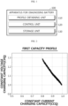
- FIG. 1 is a diagram schematically illustrating an apparatus 100 for diagnosing a battery according to an embodiment of the present disclosure.
- the apparatus 100 for diagnosing a battery may include a profile obtaining unit 110, a control unit 120, and a storage unit 130.
- the battery refers to an independent cell that has a negative electrode terminal and a positive electrode terminal and is physically separable.
- a lithium-ion battery or a lithium polymer battery may be considered a battery.
- the battery may mean a battery module in which a plurality of cells are connected in series and/or parallel. Below, for convenience of explanation, the battery is explained as meaning one independent cell.
- the profile obtaining unit 110 may be configured to obtain a capacity profile for a constant current charging capacity and a constant voltage charging capacity measured in the charging process of the battery.
- the profile obtaining unit 110 may receive a capacity profile from the outside using a provided communication module.
- the profile obtaining unit 110 may be connected to the storage unit 130 to perform wired communication and/or wireless communication.
- the profile obtaining unit 110 may access the storage unit 130 to obtain the capacity profile stored in the storage unit 130.
- the capacity profile may be a profile configured to accumulate and store the corresponding relationship between the constant current charging capacity and the constant voltage charging capacity measured at each charging cycle for the battery.
- the constant current charging capacity refers to a charging capacity when the battery is charged with a constant current (CC).
- the constant voltage charging capacity refers to a charging capacity when the battery is charged with a constant voltage (CV).
- the battery when explaining the charging process of a battery, the battery is charged with a constant current until the voltage reaches a preset cut-off voltage.
- the charging current In the constant current charging process, the charging current is kept constant, and the voltage of the battery rises in proportion to the current. Also, when the voltage of the battery reaches the cut-off voltage, the battery is charged with a constant voltage. In the constant voltage charging process, the battery voltage is kept constant, and the charging current is gradually reduced. Also, when the charging current reaches the preset cut-off current, battery charging ends.
- the capacity profile may include the corresponding relationship between the constant current charging capacity and the constant voltage charging capacity for 100 cycles.
- FIG. 2 is a diagram schematically showing a first capacity profile P1 according to an embodiment of the present disclosure.
- the first capacity profile P1 is a profile that represents the corresponding relationship between the constant current charging capacity and the constant voltage charging capacity of the first battery.
- the first capacity profile P1 is a normalized profile based on the first constant current charging capacity and the first constant voltage charging capacity.
- the normalized constant current charging capacity of the battery at the present may be 0.8, and the normalized constant voltage charging capacity may be about 1.28.
- the control unit 120 may be configured to calculate the capacity change rate between the constant current charging capacity and the constant voltage charging capacity in the capacity profile.
- control unit 120 may calculate the change rate of the constant voltage charging capacity with respect to the constant current charging capacity as a capacity change rate.
- the capacity change rate may be an instantaneous change rate or an average change rate of the constant voltage charging capacity with respect to the constant current charging capacity.
- control unit 120 may calculate an instantaneous change rate between the constant current charging capacity and the constant voltage charging capacity most recently included in the capacity profile. Specifically, the control unit 120 may obtain a capacity curve corresponding to the capacity profile through curve fitting. Also, the control unit 120 may calculate the instantaneous change rate at the desired constant current charging capacity based on the relationship equation of the capacity curve.
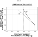
- FIG. 3 is a diagram comparing a first capacity curve QC1 of the first capacity profile P1 and a reference line RR according to an embodiment of the present disclosure.
- the first capacity curve QC1 may be a capacity curve obtained from the first capacity profile P1 using a curve fitting algorithm.
- the first capacity curve QC1 may represent the corresponding relationship between the constant current charging capacity and the constant voltage charging capacity in the constant current charging capacity section of 0.8 to 1.0.
- the control unit 120 may be configured to compare the calculated capacity change rate and a preset reference value.
- control unit 120 may compare an absolute value of the calculated capacity change rate and the preset reference value. That is, the capacity change rate calculated by the control unit 120 may be 0 or a positive real value.
- the comparison between the capacity change rate and the reference value means comparing the absolute value of the capacity change rate and the reference value.
- the reference line RR is a straight line in which the absolute value of the slope is set as the reference value.
- the reference value may be preset to 1.
- the reference line RR may be a straight line with a slope of -1. That is, the absolute value of the slope of the reference line RR and the reference value may be 1.
- control unit 120 may compare the magnitude between the calculated capacity change rate and the reference value.
- the average change rate and the instantaneous change rate of the first capacity curve QC1 may be smaller than the slope of the reference line RR. Therefore, the control unit 120 may determine that the reference value is smaller than the capacity change rate (specifically, the absolute value of the capacity change rate) of the first capacity curve QC1.
- the control unit 120 may be configured to diagnose the state of the battery based on the comparison result.
- control unit 120 may be configured to diagnose the state of the battery as an available lithium loss state, a normal state, or a positive electrode capacity deterioration state based on the comparison result. That is, the control unit 120 may diagnose the state of the battery as an available lithium loss state, a normal state, or a positive electrode capacity deterioration state based on the magnitude comparison between the reference value and the capacity change rate.
- the control unit 120 may diagnose the state of the battery as an available lithium loss state. As another example, if the capacity change rate is equal to the reference value, the control unit 120 may diagnose the state of the battery as a normal state. As still another example, if the capacity change rate exceeds the reference value, the control unit 120 may diagnose the state of the battery as a positive electrode capacity deterioration state.
- the control unit 120 may diagnose the state of the first battery as a positive electrode capacity deterioration state.
- FIG. 4 is a diagram to explain a positive electrode capacity deterioration state of a battery according to an embodiment of the present disclosure.
- the control unit 120 may diagnose the state of the battery as a positive electrode capacity deterioration state.
- FIG. 5 is a diagram to explain an available lithium loss state of the battery according to an embodiment of the present disclosure.
- the control unit 120 may diagnose the state of the battery as an available lithium loss state.
- the apparatus 100 for diagnosing a battery is characterized by being able to quickly and specifically diagnose the state of the battery depending on the degree of change between the constant current charging capacity and the constant voltage charging capacity.
- the apparatus 100 for diagnosing a battery may diagnose the state of the battery by considering only the corresponding relationship between the constant current charging capacity and the constant voltage charging capacity without being affected by the charging C-rate (Current rate). Therefore, in situations where there are no restrictions such as low-rate charging (e.g., 0.05 C charging) or data comparison at the same C-rate, the apparatus 100 for diagnosing a battery may quickly diagnose the state of the battery.
- low-rate charging e.g., 0.05 C charging
- control unit 120 included in the apparatus 100 for diagnosing a battery may optionally include processors, application-specific integrated circuits (ASICs), other chipsets, logic circuits, registers, communication modems, data processing devices, etc. known in the art to execute various control logics performed in the present disclosure.
- control logic when the control logic is implemented as software, the control unit 120 may be implemented as a set of program modules.
- the program module may be stored in the memory and executed by the control unit 120.
- the memory may be inside or outside the control unit 120 and may be connected to the control unit 120 by various well-known means.
- the apparatus 100 for diagnosing a battery may further include a storage unit 130.
- the storage unit 130 may store data necessary for operation and function of each component of the apparatus 100 for diagnosing a battery, data generated in the process of performing the operation or function, or the like.
- the storage unit 130 is not particularly limited in its kind as long as it is a known information storage means that can record, erase, update and read data.
- the information storage means may include RAM, flash memory, ROM, EEPROM, registers, and the like.
- the storage unit 130 may store program codes in which processes executable by the control unit 120 are defined.
- the control unit 120 may be configured to classify the capacity profile into at least one capacity section according to the magnitude relationship between the capacity change rate and the reference value.
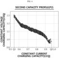
- FIG. 6 is a diagram schematically showing a second capacity profile P2 according to an embodiment of the present disclosure.
- the second capacity profile P2 is a profile that represents the corresponding relationship between the constant current charging capacity and the constant voltage charging capacity of the second battery.
- the second capacity profile P2 is a profile normalized based on the first constant current charging capacity and the first constant voltage charging capacity.
- the normalized constant current charging capacity of the battery at the present may be Q0, and the normalized constant voltage charging capacity may be about 1.3.
- FIG. 7 is a diagram comparing a second capacity curve QC2 of the second capacity profile P2 and the reference line RR according to an embodiment of the present disclosure.
- the second capacity curve QC2 may be a capacity curve obtained from second capacity profile P2 using a curve fitting algorithm.
- the second capacity curve QC2 may represent the corresponding relationship between the constant current charging capacity and the constant voltage charging capacity in the constant current charging capacity section of Q0 to Q3.
- control unit 120 may be configured to calculate the capacity change rate for each of a plurality of constant current charging capacities included in the capacity profile. Additionally, the control unit 120 may determine a target capacity among the plurality of constant current charging capacities whose corresponding capacity change rate is the same as the reference value.
- the reference line RR with the slope of the reference value may be encountered at the Q1 point and the Q2 point in the second capacity curve QC2. That is, at the point where the constant current charging capacity is Q1 and Q2, the capacity change rate of the second capacity curve QC2 may be the same as the reference value. Therefore, the control unit 120 may determine Q 1 and Q2 as a target capacity.
- the control unit 120 may be configured to classify the capacity section based on the determined target capacity.
- control unit 120 may classify Q0 to Q1 as the first capacity section RQ1, Q1 to Q2 as the second capacity section RQ2, and Q2 to Q3 as the third capacity section RQ3.
- the control unit 120 may be configured to diagnose the state of the battery for the classified capacity section.
- control unit 120 may diagnose the state of the battery for each classified capacity section.
- the control unit 120 may diagnose not only the current state of the battery but also the past state based on the capacity profile. That is, the control unit 120 may determine the state change pattern of the battery by diagnosing the state of the battery for each capacity section.
- the capacity change rate of the first capacity section RQ1 may exceed the reference value. Accordingly, the control unit 120 may diagnose the state of the battery in the first capacity section RQ1 as a positive electrode capacity deterioration state.
- the capacity change rate of the second capacity section RQ2 may be less than the reference value. Accordingly, the control unit 120 may diagnose the state of the battery in the second capacity section RQ2 as an available lithium loss state.
- the control unit 120 may diagnose the state of the battery in the third capacity section RQ3 as a positive electrode capacity deterioration state. That is, the control unit 120 may diagnose the current state of the battery as a capacity deterioration state.
- the apparatus 100 for diagnosing a battery has the advantage of being able to determine the state change pattern of the life cycle of the battery by specifically diagnosing the state of the battery for each capacity section.
- the apparatus 100 for diagnosing a battery has the advantage of being able to more efficiently collect related information that affects the change in state of the battery because it may specify the point in time when the state of the battery changes.
- control unit 120 may be configured to diagnose the state of the battery as an unusable state.
- the control unit 120 may diagnose the state of the battery as an unusable state (EOL state, End of life state).
- EOL state refers to a state in which the SOH (state of health) of the battery is less than 70%, and may be a state in which disposal of the battery is recommended. If the battery in an unusable state is used continuously, there is a problem that unexpected accidents such as explosion and fire may occur.
- the apparatus 100 for diagnosing a battery has the advantage of being able to prevent unexpected accidents in advance by diagnosing the state of the battery as an unusable state when the change in state of the battery shows a certain pattern.
- the control unit 120 may be configured to change a use condition preset for the battery to correspond to the state of the battery.
- control unit 120 may change at least one of the upper limit of the charging C-rate preset for the battery and the rest period.
- control unit 120 may reduce the upper limit of the preset charging C-rate to prevent or delay the lithium plating phenomenon in which lithium metal is precipitated on the negative electrode of the battery.
- control unit 120 may prevent high-rate charging of the battery by reducing the upper limit of the charging C-rate of the battery.
- control unit 120 may increase the rest time set for the battery. In other words, by increasing the rest time during which the battery is maintained in an unloaded state after charging or discharging of the battery is completed, the battery may be allowed to remain in the electrical equilibrium state for a long time.
- control unit 120 may change at least one of the upper limit voltage and the maximum allowable temperature preset for the battery.
- control unit 120 may reduce the upper limit voltage and/or the maximum allowable temperature set in the battery to prevent or delay capacity deterioration of the positive electrode.
- the apparatus 100 for diagnosing a battery according to an embodiment of the present disclosure has the advantage of preventing rapid deterioration of the battery by appropriately changing the use condition according to the state of the diagnosed battery.
- the apparatus 100 for diagnosing a battery may specify the point in time when the state of the battery changes, the use condition may be quickly changed to be most appropriate for the current state of the battery. Therefore, according to the apparatus 100 for diagnosing a battery, the life expectancy of the battery may be increased.
- the apparatus 100 for diagnosing a battery according to the present disclosure may be applied to a battery management system (BMS). That is, the BMS according to the present disclosure may include the apparatus 100 for diagnosing a battery described above. In this configuration, at least some of components of the apparatus 100 for diagnosing a battery may be implemented by supplementing or adding functions of the components included in a conventional BMS. For example, the profile obtaining unit 110, the control unit 120 and the storage unit 130 of the apparatus 100 for diagnosing a battery may be implemented as components of the BMS.
- the apparatus 100 for diagnosing a battery according to the present disclosure may be provided in the battery pack. That is, the battery pack according to the present disclosure may include the above-described apparatus 100 for diagnosing a battery and at least one battery cell. Additionally, the battery pack may further include electrical components (relays, fuses, etc.) and a case.
- FIG. 8 is a diagram schematically showing an exemplary configuration of a battery pack 10 according to another embodiment of the present disclosure.
- the positive electrode terminal of the battery 11 may be connected to the positive electrode terminal P+ of the battery pack 10, and the negative electrode terminal of the battery 11 may be connected to the negative electrode terminal P- of the battery pack 10.
- the measuring unit 12 may be connected to the first sensing line SL1, the second sensing line SL2, and the third sensing line SL3. Specifically, the measuring unit 12 may be connected to the positive electrode terminal of the battery 11 through the first sensing line SL1, and may be connected to the negative electrode terminal of the battery 11 through the second sensing line SL2. The measuring unit 12 may measure the voltage of the battery 11 based on the voltage measured at each of the first sensing line SL1 and the second sensing line SL2.
- the measuring unit 12 may be connected to the current measurement unit A through the third sensing line SL3.
- the current measurement unit A may be a current meter or shunt resistor that may measure the charging current and discharging current of the battery 11.
- the measuring unit 12 may calculate the charging capacity by measuring the charging current of the battery 11 through the third sensing line SL3. Additionally, the measuring unit 12 may calculate the discharge capacity by measuring the discharging current of the battery 11 through the third sensing line SL3.
- An external device may be connected to the positive electrode terminal P+ and the negative electrode terminal P- of the battery pack 10.
- the external device may be a charging/discharging device or a motor of an electric vehicle that receives power from the battery 11. While the charging and discharging device is connected to the battery pack 10 and the battery 11 is being charged, the measuring unit 12 may measure the constant current charging capacity and the constant voltage charging capacity of the battery 11.
- FIG. 9 is a diagram schematically showing an electric vehicle 900 according to still another embodiment of the present disclosure.
- the battery pack 910 may be included in a vehicle 900 such as an electric vehicle (EV) or a hybrid vehicle (HV). Additionally, the battery pack 910 may drive the vehicle 900 by supplying power to the motor through an inverter provided in the vehicle 900.
- a vehicle 900 such as an electric vehicle (EV) or a hybrid vehicle (HV).
- the battery pack 910 may drive the vehicle 900 by supplying power to the motor through an inverter provided in the vehicle 900.
- the electric vehicle 900 may include the apparatus 100 for diagnosing a battery.
- the apparatus 100 for diagnosing a battery is provided in the battery pack 910 and may diagnose the state of the battery pack 910 and/or each battery cell included in the battery pack 910.
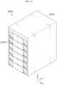
- FIG. 10 is a diagram schematically showing an ESS (Energy storage system) according to still another embodiment of the present disclosure.
- ESS Electronicgy storage system
- the ESS includes a plurality of rack cases 1010 and a plurality of battery modules 1020.
- the plurality of battery modules 1020 may be configured to be accommodated in the rack case 1010 in a vertically arranged form.
- Each of the plurality of battery modules 1020 may include the apparatus 100 for diagnosing a battery.
- the apparatus 100 for diagnosing a battery may diagnose the state of a corresponding battery module 1020 and/or a battery cell included in the battery module 1020.
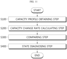
- FIG. 11 is a diagram schematically showing a method for diagnosing a battery according to still another embodiment of the present disclosure.
- each step of the method for diagnosing a battery may be performed by the apparatus 100 for diagnosing a battery.
- the content overlapping with the previously described content will be briefly described or omitted.
- the method for diagnosing a battery may include a capacity profile obtaining step (S100), a capacity change rate calculating step (S200), a comparing step (S300), and a state diagnosing step (S400).
- the capacity profile obtaining step (S100) is a step of obtaining a capacity profile for a constant current charging capacity and a constant voltage charging capacity measured in a charging process of a battery, and may be performed by the profile obtaining unit 110.
- the profile obtaining unit 110 may obtain a capacity profile from the outside or the storage unit 130.
- the capacity change rate calculating step (S200) is a step of calculating a capacity change rate between the constant current charging capacity and the constant voltage charging capacity in the capacity profile, and may be performed by the control unit 120.
- control unit 120 may calculate the capacity change rate by calculating the ratio of the constant voltage charging capacity to the constant current charging capacity.
- the comparing step (S300) is a step of comparing the calculated capacity change rate and a preset reference value, and may be performed by the control unit 120.
- control unit 120 may compare the magnitudes of the calculated capacity change rate and the preset reference value.
- the state diagnosing step (S400) is a step of diagnosing the state of the battery based on the comparison result, and may be performed by the control unit 120.
- the control unit 120 may diagnose the state of the battery as an available lithium loss state. As another example, if the capacity change rate is equal to the reference value, the control unit 120 may diagnose the state of the battery as a normal state. As another example, if the capacity change rate exceeds the reference value, the control unit 120 may diagnose the state of the battery as a positive electrode capacity deterioration state.
- control unit 120 may classify the capacity profile into a plurality of capacity sections and specifically diagnose the state of the battery in each capacity section. Furthermore, the control unit 120 may diagnose the state of the battery as an unusable state when the state change of the battery shows a certain pattern (in which a positive electrode capacity deterioration state, an available lithium loss state, and a positive electrode capacity deterioration state are sequentially diagnosed).
- the embodiments of the present disclosure described above may not be implemented only through an apparatus and a method, but may be implemented through a program that realizes a function corresponding to the configuration of the embodiments of the present disclosure or a recording medium on which the program is recorded.
- the program or recording medium may be easily implemented by those skilled in the art from the above description of the embodiments.
Landscapes
- Physics & Mathematics (AREA)
- General Physics & Mathematics (AREA)
- Secondary Cells (AREA)
- Charge And Discharge Circuits For Batteries Or The Like (AREA)
- Tests Of Electric Status Of Batteries (AREA)
Applications Claiming Priority (2)
| Application Number | Priority Date | Filing Date | Title |
|---|---|---|---|
| KR1020220119803A KR102688039B1 (ko) | 2022-09-22 | 2022-09-22 | 배터리 진단 장치 및 방법 |
| PCT/KR2023/014442 WO2024063577A1 (ko) | 2022-09-22 | 2023-09-21 | 배터리 진단 장치 및 방법 |
Publications (2)
| Publication Number | Publication Date |
|---|---|
| EP4471444A1 true EP4471444A1 (de) | 2024-12-04 |
| EP4471444A4 EP4471444A4 (de) | 2025-07-09 |
Family
ID=90455021
Family Applications (1)
| Application Number | Title | Priority Date | Filing Date |
|---|---|---|---|
| EP23868629.9A Pending EP4471444A4 (de) | 2022-09-22 | 2023-09-21 | Batteriediagnosevorrichtung und -verfahren |
Country Status (6)
| Country | Link |
|---|---|
| EP (1) | EP4471444A4 (de) |
| JP (1) | JP2025525758A (de) |
| KR (1) | KR102688039B1 (de) |
| CN (1) | CN118525214A (de) |
| CA (1) | CA3246282A1 (de) |
| WO (1) | WO2024063577A1 (de) |
Families Citing this family (4)
| Publication number | Priority date | Publication date | Assignee | Title |
|---|---|---|---|---|
| KR20250150291A (ko) * | 2024-04-11 | 2025-10-20 | 주식회사 엘지에너지솔루션 | 배터리 프로파일 생성 장치 및 방법 |
| KR20250175207A (ko) * | 2024-06-07 | 2025-12-16 | 주식회사 엘지에너지솔루션 | 배터리 관리 장치 및 방법 |
| KR20250175208A (ko) * | 2024-06-07 | 2025-12-16 | 주식회사 엘지에너지솔루션 | 배터리 관리 장치 및 방법 |
| KR20260006974A (ko) * | 2024-07-05 | 2026-01-13 | 주식회사 엘지에너지솔루션 | 배터리 진단 장치 및 그 방법 |
Family Cites Families (12)
| Publication number | Priority date | Publication date | Assignee | Title |
|---|---|---|---|---|
| JP3460567B2 (ja) * | 1998-01-19 | 2003-10-27 | 松下電器産業株式会社 | 二次電池の劣化検出方法及び劣化検出機能を具備した充電器 |
| CN102393509A (zh) * | 2011-09-30 | 2012-03-28 | 湖南大学 | 一种无损评估锂离子电池性能的方法 |
| JP5928815B2 (ja) * | 2012-08-24 | 2016-06-01 | トヨタ自動車株式会社 | 非水電解質二次電池の製造方法 |
| KR102117316B1 (ko) * | 2016-07-06 | 2020-06-01 | 주식회사 엘지화학 | Cc/cv 비율을 이용한 이차전지의 가용 용량 추정 장치 |
| CN111308379B (zh) * | 2020-03-13 | 2021-02-02 | 北京理工大学 | 一种基于局部恒压充电数据的电池健康状态估计方法 |
| CN111366628A (zh) * | 2020-03-13 | 2020-07-03 | 东莞东阳光科研发有限公司 | 一种高镍正极材料电化学性能的预测方法 |
| KR102843320B1 (ko) * | 2020-06-03 | 2025-08-05 | 주식회사 엘지에너지솔루션 | 배터리 상태 진단 장치 및 방법 |
| US12044737B2 (en) * | 2021-02-08 | 2024-07-23 | Hong Kong Applied Science and Technology Research Institute Company Limited | Fast screening of rechargeable batteries using sectional constant-current impulse ratio (SCCIR) calibration with constant-current followed by constant-voltage charging |
| KR102488019B1 (ko) | 2021-02-22 | 2023-01-12 | 주식회사 풍산 | 발사체의 사격제원계산 시스템과 사격제원 계산 방법 |
| CN114035057A (zh) * | 2021-12-13 | 2022-02-11 | 航天锂电科技(江苏)有限公司 | 长循环锂电池容量保持率的评估方法 |
| KR102618037B1 (ko) * | 2022-06-20 | 2023-12-27 | 주식회사 엘지에너지솔루션 | 배터리 진단 장치, 배터리 진단 방법 및 배터리 진단 시스템 |
| JP7579622B2 (ja) * | 2022-07-08 | 2024-11-08 | プライムプラネットエナジー&ソリューションズ株式会社 | 蓄電デバイスの評価方法及び製造方法 |
-
2022
- 2022-09-22 KR KR1020220119803A patent/KR102688039B1/ko active Active
-
2023
- 2023-09-21 EP EP23868629.9A patent/EP4471444A4/de active Pending
- 2023-09-21 WO PCT/KR2023/014442 patent/WO2024063577A1/ko not_active Ceased
- 2023-09-21 CA CA3246282A patent/CA3246282A1/en active Pending
- 2023-09-21 JP JP2025504121A patent/JP2025525758A/ja active Pending
- 2023-09-21 CN CN202380018268.5A patent/CN118525214A/zh active Pending
Also Published As
| Publication number | Publication date |
|---|---|
| CN118525214A (zh) | 2024-08-20 |
| KR102688039B1 (ko) | 2024-07-23 |
| CA3246282A1 (en) | 2025-06-13 |
| EP4471444A4 (de) | 2025-07-09 |
| KR20240040909A (ko) | 2024-03-29 |
| WO2024063577A1 (ko) | 2024-03-28 |
| JP2025525758A (ja) | 2025-08-07 |
Similar Documents
| Publication | Publication Date | Title |
|---|---|---|
| EP4199182B1 (de) | Batteriediagnosevorrichtung und -verfahren | |
| EP4471444A1 (de) | Batteriediagnosevorrichtung und -verfahren | |
| EP4376161A1 (de) | Vorrichtung und verfahren zur verwaltung einer batterie | |
| KR102759313B1 (ko) | 배터리 진단 장치 및 방법 | |
| US12352818B2 (en) | Battery management apparatus and method | |
| EP4145589A1 (de) | Batterieklassifizierungsvorrichtung und -verfahren | |
| EP4465063A1 (de) | Vorrichtung und verfahren zur batteriediagnose | |
| EP4471443A1 (de) | Vorrichtung und verfahren zur batteriediagnose | |
| EP4467999B1 (de) | Vorrichtung und verfahren zur batteriezustandsdiagnose | |
| EP4152025B1 (de) | Vorrichtung und verfahren zur diagnose einer batterie | |
| EP4167345B1 (de) | Batteriediagnosevorrichtung und verfahren | |
| EP4729963A1 (de) | Vorrichtung und verfahren zur batteriediagnose | |
| EP4579261A1 (de) | Batteriediagnosevorrichtung und -verfahren | |
| EP4468002A1 (de) | Batteriediagnosevorrichtung und -verfahren | |
| EP4576491A1 (de) | Vorrichtung und verfahren zum laden einer batterie | |
| EP4517353A1 (de) | Vorrichtung und verfahren zur batteriediagnose | |
| EP4733786A1 (de) | Vorrichtung und verfahren zur batteriediagnose | |
| US20250244402A1 (en) | Apparatus and method for diagnosing battery | |
| EP4675294A1 (de) | Vorrichtung und verfahren zur batteriediagnose | |
| EP4715404A1 (de) | Vorrichtung und verfahren zur verwaltung einer batterie | |
| EP4597134A1 (de) | Vorrichtung und verfahren zur batteriediagnose | |
| EP4549974A1 (de) | Batteriediagnosevorrichtung und -verfahren | |
| EP4650804A1 (de) | Vorrichtung und verfahren zur batteriediagnose | |
| CN121368726A (zh) | 用于诊断电池的装置和方法 | |
| CN121443960A (zh) | 用于诊断电池的装置和方法 |
Legal Events
| Date | Code | Title | Description |
|---|---|---|---|
| STAA | Information on the status of an ep patent application or granted ep patent |
Free format text: STATUS: THE INTERNATIONAL PUBLICATION HAS BEEN MADE |
|
| PUAI | Public reference made under article 153(3) epc to a published international application that has entered the european phase |
Free format text: ORIGINAL CODE: 0009012 |
|
| STAA | Information on the status of an ep patent application or granted ep patent |
Free format text: STATUS: REQUEST FOR EXAMINATION WAS MADE |
|
| 17P | Request for examination filed |
Effective date: 20240829 |
|
| AK | Designated contracting states |
Kind code of ref document: A1 Designated state(s): AL AT BE BG CH CY CZ DE DK EE ES FI FR GB GR HR HU IE IS IT LI LT LU LV MC ME MK MT NL NO PL PT RO RS SE SI SK SM TR |
|
| A4 | Supplementary search report drawn up and despatched |
Effective date: 20250611 |
|
| RIC1 | Information provided on ipc code assigned before grant |
Ipc: G01R 31/367 20190101ALI20250604BHEP Ipc: G01R 31/3842 20190101ALI20250604BHEP Ipc: G01R 31/392 20190101ALI20250604BHEP Ipc: G01R 31/396 20190101AFI20250604BHEP |
|
| DAV | Request for validation of the european patent (deleted) | ||
| DAX | Request for extension of the european patent (deleted) | ||
| GRAP | Despatch of communication of intention to grant a patent |
Free format text: ORIGINAL CODE: EPIDOSNIGR1 |
|
| STAA | Information on the status of an ep patent application or granted ep patent |
Free format text: STATUS: GRANT OF PATENT IS INTENDED |
|
| INTG | Intention to grant announced |
Effective date: 20260120 |