EP4471479A1 - Optische linse - Google Patents
Optische linse Download PDFInfo
- Publication number
- EP4471479A1 EP4471479A1 EP23746117.3A EP23746117A EP4471479A1 EP 4471479 A1 EP4471479 A1 EP 4471479A1 EP 23746117 A EP23746117 A EP 23746117A EP 4471479 A1 EP4471479 A1 EP 4471479A1
- Authority
- EP
- European Patent Office
- Prior art keywords
- lens
- optical lens
- optical
- object side
- focal length
- Prior art date
- Legal status (The legal status is an assumption and is not a legal conclusion. Google has not performed a legal analysis and makes no representation as to the accuracy of the status listed.)
- Granted
Links
Images




Classifications
-
- G—PHYSICS
- G02—OPTICS
- G02B—OPTICAL ELEMENTS, SYSTEMS OR APPARATUS
- G02B13/00—Optical objectives specially designed for the purposes specified below
- G02B13/001—Miniaturised objectives for electronic devices, e.g. portable telephones, webcams, PDAs, small digital cameras
- G02B13/0015—Miniaturised objectives for electronic devices, e.g. portable telephones, webcams, PDAs, small digital cameras characterised by the lens design
- G02B13/002—Miniaturised objectives for electronic devices, e.g. portable telephones, webcams, PDAs, small digital cameras characterised by the lens design having at least one aspherical surface
- G02B13/0045—Miniaturised objectives for electronic devices, e.g. portable telephones, webcams, PDAs, small digital cameras characterised by the lens design having at least one aspherical surface having five or more lenses
-
- G—PHYSICS
- G02—OPTICS
- G02B—OPTICAL ELEMENTS, SYSTEMS OR APPARATUS
- G02B13/00—Optical objectives specially designed for the purposes specified below
- G02B13/001—Miniaturised objectives for electronic devices, e.g. portable telephones, webcams, PDAs, small digital cameras
- G02B13/0055—Miniaturised objectives for electronic devices, e.g. portable telephones, webcams, PDAs, small digital cameras employing a special optical element
- G02B13/006—Miniaturised objectives for electronic devices, e.g. portable telephones, webcams, PDAs, small digital cameras employing a special optical element at least one element being a compound optical element, e.g. cemented elements
-
- G—PHYSICS
- G02—OPTICS
- G02B—OPTICAL ELEMENTS, SYSTEMS OR APPARATUS
- G02B13/00—Optical objectives specially designed for the purposes specified below
- G02B13/04—Reversed telephoto objectives
-
- G—PHYSICS
- G02—OPTICS
- G02B—OPTICAL ELEMENTS, SYSTEMS OR APPARATUS
- G02B13/00—Optical objectives specially designed for the purposes specified below
- G02B13/06—Panoramic objectives; So-called "sky lenses" including panoramic objectives having reflecting surfaces
-
- G—PHYSICS
- G02—OPTICS
- G02B—OPTICAL ELEMENTS, SYSTEMS OR APPARATUS
- G02B9/00—Optical objectives characterised both by the number of the components and their arrangements according to their sign, i.e. + or -
- G02B9/62—Optical objectives characterised both by the number of the components and their arrangements according to their sign, i.e. + or - having six components only
-
- G—PHYSICS
- G02—OPTICS
- G02B—OPTICAL ELEMENTS, SYSTEMS OR APPARATUS
- G02B3/00—Simple or compound lenses
- G02B2003/0093—Simple or compound lenses characterised by the shape
Definitions
- the disclosure relates to the technical field of imaging lenses, in particular to an optical lens.
- An automotive lens is a key component of the automatic driving assistance system to obtain external information, and it also needs to be upgraded to meet the requirements of the present stage.
- the conventional automatic driving assistance system generally depends on a long-focus lens and a wide-angle lens.
- the long-focus lens has a long focal length, it has a small field of view, and it is generally used to capture objects at a long-distance for observation.
- the wide-angle lens has a large field of view, it has a short focal length, and it is generally used to capture objects at a short-distance for observation. Therefore, there is a need to design an optical lens which integrates functions of the long-focus lens and the wide-angle lens, and has a large aperture, a large field of view and a high resolution, so as to replace multiple lenses each having a single function in the traditional automatic driving assistance system.
- Embodiments of the present disclosure provide an optical lens with a large aperture, a large field of view and a high resolution.
- the embodiments of the present disclosure provide an optical lens including a total of six lenses. From an object side to an imaging plane along an optical axis of the optical lens, the optical lens sequentially includes: a first lens with a negative refractive power, both an object side surface and the image side surface of the first lens being concave; a second lens with a negative refractive power, an object side surface of the second lens being concave, and an image side surface of the second lens being convex; a third lens with a positive refractive power, both an object side surface and an image side surface of the third lens being convex; a fourth lens with a positive refractive power, both an object side surface and an image side surface of the fourth lens being convex; a fifth lens with a negative refractive power, an object side surface of the fifth lens being concave, and an image side surface of the fifth lens being convex; a sixth lens with a positive refractive power, an object side surface of the sixth lens is convex, and an image side surface of the
- the fourth lens and the fifth lens are cemented to form a cemented lens.
- An effective focal length f of the optical lens and a true image height IH corresponding to a maximum field of view of the optical lens meet an expression: 0.55 ⁇ f /IH ⁇ 0.65.
- An aperture HD1 of the object side surface of the first lens corresponding to half of the maximum field of view of the optical lens and an aperture D1 of the object side surface of the first lens corresponding to the maximum field of view meet an expression: 0.5 ⁇ HD1/D1 ⁇ 0.6.
- the effective focal length f of the optical lens meets an expression: 5.9mm ⁇ f ⁇ 6.5mm.
- the true image height IH corresponding to the maximum field of view of the optical lens meets an expression: 9.5mm ⁇ IH ⁇ 10.5mm.
- an f-number of the optical lens meets an expression: 1.7 ⁇ FNO ⁇ 1.9.
- the effective focal length f of the optical lens and a focal length f 1 of the first lens meet an expression: -1.2 ⁇ f 1/ f ⁇ -1.0.
- a radius of curvature R1 of the object side surface of the first lens and a radius of curvature R2 of the image side surface of the first lens meet an expression: 0.8 ⁇ (R1+R2)/(R1-R2) ⁇ 0.9.
- the effective focal length f of the optical lens and a focal length f 2 of the second lens meet an expression: -18.5 ⁇ f 2/ f ⁇ -11.5.
- a radius of curvature R3 of the object side surface of the second lens, a radius of curvature R4 of the image side surface of the second lens, and a central thickness CT2 of the second lens meet an expression: 1.05 ⁇ R3/(R4+CT2) ⁇ 1.20.
- the effective focal length f of the optical lens, a focal length f 3 of the third lens, and a radius of curvature R5 of the object side surface of the third lens meet expressions: 2.0 ⁇ f 3/ f ⁇ 2.2, and 1.10 ⁇ R5/ f 3 ⁇ 1.25.
- the effective focal length f of the optical lens and a focal length f 4 of the fourth lens meet an expression: 1.2 ⁇ f 4/ f ⁇ 1.9.
- the effective focal length f of the optical lens and a focal length f 5 of the fifth lens, a radius of curvature R9 of the object side surface of the fifth lens, and a radius of curvature R10 of the image side surface of the fifth lens meet expressions: -2.2 ⁇ f 5/ f ⁇ -1.8, and 1.10 ⁇ R10/(R9+/5) ⁇ 1.35.
- the effective focal length f of the optical lens and a focal length f 6 of the sixth lens, a radius of curvature R11 of the object side surface of the sixth lens and a radius of curvature R12 of the image side surface of the sixth lens meet expressions: 2.8 ⁇ f 6/ f ⁇ 3.9, and -3.0 ⁇ (R11+R12)/(R11-R12) ⁇ -1.0.
- a large aperture, a large field angle of view and a high resolution of the optical lens are enabled by reasonably matching lens shapes among the lenses and combining the refractive power of various lenses.
- first, second, third, etc. are only used to distinguish one feature from another, and do not mean any limitation on the features. Therefore, a first lens discussed below may also be called as a second lens or a third lens without departing from the teaching of the present disclosure.
- a paraxial region refers to a region near the optical axis. If a surface of the lens is convex and a convex position of the surface is not defined, it means that the surface of the lens is convex at least in the paraxial region. If a surface of the lens is concave and a concave position of the surface is not defined, it means that the surface of the lens is concave at least in the paraxial region.
- a surface of each lens closest to the to-be-captured object is referred to as an object side surface of the lens, and a surface of each lens closest to the imaging plane is referred to as an image side surface of the lens.
- An optical lens provided in the embodiments of the present disclosure includes sequentially, from an object side surface to an imaging surface: a first lens, a second lens, a third lens, a fourth lens, a fifth lens and a sixth lens.
- the first lens has a negative refractive power, and has a concave object side surface and a concave image side surface.
- Such refractive power and surfaces of the first lens are beneficial to collect light from a large field of view as much as possible to enter the following optical lenses.
- the second lens has a negative refractive power, and has a concave object side surface and a convex image side surface.
- Such refractive power and surfaces of the second lens are beneficial to collect the light incident from the first lens, and make a travel path of the light have a smooth transition. This is also beneficial to reduce a front aperture of the optical lens, and reduce a volume of the optical lens, which is helpful in miniaturization of the optical lens and reduction of the cost.
- the third lens has a positive refractive power, and has a convex object side surface and a convex image side surface.
- Such refractive power and surfaces of the third lens are beneficial to converge the light, and make the diverged lights enter the subsequent light path, that is, a smooth transition is provided in the travel path of the light.
- the fourth lens has a positive refractive power, and has a convex object side surface and a convex image side surface.
- Such refractive power and surfaces of the fourth lens are beneficial to converge the light, and make the diverged lights enter the subsequent light path, that is, a smooth transition is further provided in the travel path of the light.
- the fifth lens has a negative refractive power, and has a concave object side surface and a convex image side surface.
- Such refractive power and surfaces of the fifth lens plays a certain role in correcting aberration, and are beneficial to avoid the light from being too divergent in the subsequent light path.
- the image side surface of the fourth lens and the object side surface of the fifth lens are cemented to each other.
- the fourth lens and the fifth lens into a cemented lens, it takes charge of the overall chromatic aberration correction of the optical system, and effectively corrects the aberration. It also alleviates problems of tolerance sensitivity such as tilt/off-of-center of the lenses caused during assembly, and improves the production yield.
- the sixth lens has a positive refractive power and has a convex object side surface and a concave image side surface.
- Such refractive power and surfaces of the sixth lens are beneficial to effectively transmit more light to the imaging plane, correct astigmatism and field curvature, and improve the image resolving ability of the optical lens.
- the sixth lens has aspherical surfaces, which is beneficial to the flatness of the surfaces, and can eliminate the aberration that occurs during imaging, thus improving the imaging quality of the optical lens.
- a stop is provided between the second lens and the fourth lens, and the stop is configured to limit the beam of the light. This further improves the imaging quality of the optical lens.
- the stop is provided between the second lens and the fourth lens, it is beneficial to gather the light entering the optical system, and reduce the front aperture of the optical lens.
- an effective focal length f of the optical lens meets an expression: 5.9 mm ⁇ f ⁇ 6.5 mm. This is helpful to improve the ability of the lens in highlighting a subject and an ability in shooting a distant scene.
- an f-number of the optical lens meet an expression: 1.7 ⁇ FNO ⁇ 1.9. This ensures an illuminance at an edge imaging region of the optical lens while having both a long focal length and a large field of view.
- a true image height IH corresponding to the maximum field of view meets an expression: 9.5 mm ⁇ IH ⁇ 10.5 mm. This is beneficial to realize an imaging effect of a large imaging plane of the optical lens, thus having high optical performance. It can further enable the optical lens to match image sensors of different specifications.
- a chief ray angle CRA on the imaging plane at a full field of view of the optical lens meets an expression: 0° ⁇ CRA ⁇ 6.5°. This can bring a large allowable error between the CRA of the optical lens and a CRA of a chip sensor, and can also ensure the illumination at an edge imaging region.
- the effective focal length f of the optical lens and the true image height IH corresponding to the maximum field of view meets an expression: 0.55 ⁇ f /IH ⁇ 0.65. This can ensure that the optical lens has a large imaging surface, and meets an imaging requirement of a chip having a large target plane.
- a sum ⁇ CT of center thicknesses of all the lenses and a total track length TTL of the optical lens meet an expression: 0.55 ⁇ CT/TTL ⁇ 0.70. This is beneficial to short the total length of the optical lens.
- an aperture HD1 of the object side surface of the first lens corresponding to half of the maximum field of view of the optical lens and an aperture D1 of the object side surface of the first lens corresponding to the maximum field of view meet an expression: 0.5 ⁇ HD1/D1 ⁇ 0.6. This can ensure that a central field of view of the optical lens is concentrated near the optical axis, enable coma and astigmatism to be reduced as much as possible, and also enable a great illumination of an edge field of view.
- the effective focal length f of the optical lens and a focal length f 1 of the first lens meet an expression: -1.2 ⁇ f 1/ f ⁇ -1.0. This enables the first lens to have a small negative refractive power, and is beneficial to increase the back focal length of the optical lens.
- the effective focal length f of the optical lens and a focal length f 2 of the second lens meet an expression: -18.5 ⁇ f 2/ f ⁇ -11.5. This enables the second lens to have a large negative refractive power, which is beneficial to balance the astigmatism and field curvature of the optical lens.
- the effective focal length f of the optical lens and a focal length f 3 of the third lens meet an expression: 2.0 ⁇ f 3/ f ⁇ 2.2. This enables the third lens to have a small positive refractive power, which is beneficial to balance various aberrations of the optical lens.
- the effective focal length f of the optical lens and a focal length f 4 of the fourth lens meet an expression: 1.2 ⁇ f 4/ f ⁇ 1.9. This enables the fourth lens to have a small positive refractive power, which is beneficial to balance various aberrations of the optical lens.
- the effective focal length f of the optical lens and a focal length f 5 of the fifth lens meet an expression: -2.2 ⁇ f 5/ f ⁇ -1.8. This enables the fifth lens to have a small negative refractive power, which is beneficial to correct the aberration caused its previous lenses, and avoid the light from being too divergent in the subsequent light path.
- the effective focal length f of the optical lens and a focal length f 6 of the sixth lens meet an expression: 2.8 ⁇ f 6/ f ⁇ 3.9. This enables the sixth lens to have a large positive refractive power, which is beneficial to balance the astigmatism and field curvature of the optical lens.
- a radius of curvature R1 of the object side surface of the first lens and a radius of curvature R2 of the image side surface of the first lens meet an expression: 0.8 ⁇ (R1+R2)/(R1-R2) ⁇ 0.9. This is beneficial to increase the field of view of the optical lens, balance the spherical aberration and field curvature of the optical lens, and improve the imaging quality of the optical lens.
- a radius of curvature R3 of the object side surface, a radius of curvature R4 of the image side surface of the second lens, and a central thickness CT2 of the second lens meet an expression: 1.05 ⁇ R3/(R4+CT2) ⁇ 1.20. This is beneficial to make shapes of the object-side surface and the image side surface of the second lens be approximately concentric circles, balance the astigmatism and field curvature generated by the second lens, and improve the imaging quality of the optical lens.
- a radius of curvature R5 of the object side surface of the third lens and the focal length f 3 of the third lens in the optical lens meet an expression: 1.10 ⁇ R5/ f 3 ⁇ 1.25. This is beneficial to reduce a sensitivity of the third lens, balance various aberrations of the optical lens, and improve the imaging quality of the optical lens.
- a radius of curvature R10 of the image side surface of the fifth lens and the focal length f 5 of the fifth lens meet an expression: 1.10 ⁇ R10/(R9+ f 5) ⁇ 1.35. This is beneficial to control the refraction angle of the light at the fifth lens, balance various aberrations generated by the fifth lens, and improve the imaging quality of the optical lens.
- a radius of curvature R11 of the object side surface and a radius of curvature R12 of the image side surface of the sixth lens in the optical lens meet an expression: -2.0 ⁇ (R1 1+R12)/(R1 1-R12) ⁇ -1.0.
- a center thickness CT3 of the third lens and the total track length TTL of the optical lens meet an expression: 0.08 ⁇ CT3/TTL ⁇ 0.26. This is beneficial to correct the field curvature by the thick third lens.
- a center thickness CT4 of the fourth lens and the total track length TTL of the optical lens meet an expression: 0.11 ⁇ CT4/TTL ⁇ 0.16. This is beneficial to correct the field curvature by the thick fourth lens.
- a center thickness CT6 of the sixth lens and the total track length TTL of the optical lens meet an expression: 0.11 ⁇ CT6/TTL ⁇ 0.2. This is beneficial to correct the field curvature by the thick sixth lens.
- Z represents a distance between a position on the surface and a vertex of the surface along the optical axis
- h a distance from the optical axis to the position on the surface
- c represents the curvature of the vertex of the surface
- K represents a quadratic surface coefficient
- A represents a second-order surface coefficient
- B represents a fourth-order surface coefficient
- C represents a sixth-order surface coefficient
- D represents an eighth-order surface coefficient
- E represents a tenth-order surface coefficient
- F represents a twelfth-order surface coefficient.
- the thickness, the radius of curvature, and the material selection of each lens in the optical lens are different, which may refer to the parameter table of the respective embodiments.
- the following embodiments just illustrate preferred implementations of the present disclosure.
- the implementations of the present disclosure are not limited only by the following embodiments, and any other variations, substitutions, combinations or simplifications, that are made without departing from the concept of the present disclosure, should be regarded as equivalent implementations, and fall within the protection scope of the present disclosure.
- the structure of an optical lens provided in Embodiment 1 of the present disclosure is illustrated. From an object side to an imaging plane along an optical axis, the optical lens sequentially includes: a first lens L1, a second lens L2, a stop ST, a third lens L3, a fourth lens L4, a fifth lens L5, a sixth lens L6, a filter G1 and a protective glass G2.
- the first lens L1 has a negative refractive power.
- the object side surface S1 of the first lens L1 is concave, and the image side surface S2 of the first lens is concave.
- the second lens L2 has a negative refractive power.
- the object side surface S3 of the second lens L2 is concave, and the image side surface S4 of the second lens L2 is convex. Then is the stop ST.
- the third lens L3 has a positive refractive power. Both the object side surface S5 and the image side surface S6 of the third lens L3 are convex.
- the fourth lens L4 has a positive refractive power. Both the object side surface S7 and the image side surface S8 of the fourth lens L4 are convex.
- the fifth lens L5 has a negative refractive power.
- the object side surface S9 of the fifth lens L5 is concave, and the image side surface S10 of the fifth lens L5 is convex.
- the sixth lens L6 has a positive refractive power.
- the object side surface S11 of the sixth lens L6 is convex, and the image side surface S12 of the sixth lens L6 is concave.
- the fourth lens L4 and the fifth lens L5 may be cemented to form a cemented lens.
- Table 1-1 The relevant parameters of each lens in the optical lens provided in Embodiment 1 of the present disclosure are shown in Table 1-1.
- Table 1-1 Surface No. Surface type Radius of curvature R (mm) Thickness D/ Distance L(mm) Refractive index Nd Abbe number Vd Object plane Plane Infinity Infinity S1 First lens Spherical surface -71.51 1.00 1.76 52.34 S2 Spherical surface 5.86 3.27 S3 Second Spherical surface -7.47 4.31 1.50 81.61 S4 lens Spherical surface -10.80 0.51 ST Stop Plane Infinity -0.41 S5 Third lens Spherical surface 14.89 10.48 1.88 40.81 S6 Spherical surface -27.56 1.67 S7 Fourth lens Fifth lens Spherical surface 13.71 4.59 1.50 81.61 S8/S9 Spherical surface -7.92 0.53 1.95 17.94 S10 Spherical surface -23.51 5.40 S11 Sixth lens Aspheric surface 12.96 4.28 1.81 40.73
- Table 1-2 The parameters of surfaces of the aspheric lenses in the optical lens provided in Embodiment 1 of the present disclosure are shown in Table 1-2.
- Table 1-2 Surface No. K A B C D E F S11 -15.29 0.00E+00 5.94E-04 -3.05E-05 8.18E-07 -1.62E-08 1.32E-10 S12 -0.52 0.00E+00 -3.29E-04 -8.10E-06 1.72E-07 -2.75E-09 2.58E-11
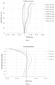
- the field curvature curves of the optical lens are shown in FIG. 2
- the axial aberration curves of the optical lens are shown in FIG. 3
- the lateral chromatic aberration curves of the optical lens are shown in FIG. 4
- the MTF curves of the optical lens are shown in FIG. 5 .
- the field curvature curves of Embodiment 1 are illustrated in FIG. 2 , which represent curvature degrees of light at different wavelengths on a meridional plane and a sagittal plane.
- the horizontal axis represents an offset (unit: millimeter), and the vertical axis represents a half field of view (unit: degree (°)). It can be seen from the graph that the field curvatures of the meridional plane and the sagittal plane are within ⁇ 0.03 mm, which shows that the field curvatures of the optical lens are well corrected.
- the axial aberration curves of Embodiment 1 are illustrated in FIG. 3 , which represent aberrations on the optical axis at the imaging plane.
- the horizontal axis represents the axial aberration (unit: millimeter), and the vertical axis represents the normalized pupil radius. It can be seen from the graph that an offset of the axial aberration is within ⁇ 0.015 mm, which shows that optical lens can effectively correct the axial aberration thereof.
- the lateral chromatic aberration curves of Embodiment 1 are illustrated in FIG. 4 , which represent chromatic aberrations of various wavelengths, relative to a center wavelength (0.55 ⁇ m), at different image heights on the imaging plane.
- the horizontal axis represents the lateral chromatic aberrations (unit: micrometer) of each wavelength relative to the center wavelength, and the vertical axis represents a normalized field of view. It can be seen from the graph that the lateral chromatic aberrations of the longest wavelength and the shortest wavelength are all within ⁇ 5 ⁇ m, which shows that the optical lens can effectively correct the chromatic aberration of the edge field of view and the secondary spectrum of the entire imaging plane.
- the MTF curves of Embodiment 1 are illustrated in FIG. 5 , which represent imaging modulation of the optical lens at different spatial frequencies and different fields of view.
- the horizontal axis represents spatial frequency (unit: lp/mm), and the vertical axis represents MTF value. It can be seen from the graph that the MTF values in the embodiment are all above 0.5 in the full field of view. In a range of (0-120) lp/mm, the MTF curves uniformly and smoothly decrease from the center to the edge field of view. A good imaging quality and a good detail resolution capability are all enabled at either a low frequency or a high frequency.
- the optical lens sequentially includes: a first lens L1, a second lens L2, a third lens L3, a stop ST, a fourth lens L4, a fifth lens L5, a sixth lens L6, a filter G1 and a protective glass G2.
- the first lens L1 has a negative refractive power.
- the object side surface S1 of the first lens L1 is concave, and the image side surface S2 of the first lens is concave.
- the second lens L2 has a negative refractive power.
- the object side surface S3 of the second lens L2 is concave, and the image side surface S4 of the second lens L2 is convex.
- the third lens L3 has a positive refractive power. Both the object side surface S5 and the image side surface S6 of the third lens L3 are convex. Then is the stop ST.
- the fourth lens L4 has a positive refractive power. Both the object side surface S7 and the image side surface S8 of the fourth lens L4 are convex.
- the fifth lens L5 has a negative refractive power.
- the object side surface S9 of the fifth lens L5 is concave, and the image side surface S10 of the fifth lens L5 is convex.
- the sixth lens L6 has a positive refractive power.
- the object side surface S11 of the sixth lens L6 is convex, and the image side surface S12 of the sixth lens L6 is concave.
- the fourth lens L4 and the fifth lens L5 may be cemented to form a cemented lens.
- Table 2-1 The relevant parameters of each lens in the optical lens provided in Embodiment 2 of the present disclosure are shown in Table 2-1.
- Table 2-1 Surface No. Surface type Radius of curvature R (mm) Thickness D/ Distance L(mm) Refractive index Nd Abbe number Vd Object plane Plane Infinity Infinity S1 First lens Spherical surface -79.42 1.00 1.84 42.73 S2 Spherical surface 6.24 3.64 S3 Second lens Spherical surface -7.29 3.46 1.73 54.67 S4 Spherical surface -10.19 0.10 S5 Third lens Spherical surface 15.99 4.02 1.91 35.25 S6 Spherical surface -42.59 2.93 ST Stop Plane Infinity 3.66 S7 Fourth lens Fifth lens Spherical surface 14.30 4.50 1.60 65.46 S8/S9 Spherical surface -7.88 0.98 1.95 17.94 S10 Spherical surface -26.54 3.74 S11 Sixth lens Aspheric surface 14.83 7.92 1.81 40.73 S12 Asp
- Table 2-2 The parameters of surfaces of the aspheric lenses in the optical lens provided in Embodiment 2 of the present disclosure are shown in Table 2-2.
- Table 2-2 Surface No. K A B C D E F S11 -2.89 0.00E+00 -9.51E-05 -1.71E-06 2.26E-08 -1.39E-09 9.50E-12 S12 -33.60 0.00E+00 -4.32E-04 -4.07E-06 7.88E-08 -1.69E-10 -2.72E-12
- the field curvature curves of the optical lens are shown in FIG. 7
- the axial aberration curves of the optical lens are shown in FIG. 8
- the lateral chromatic aberration curves of the optical lens are shown in FIG. 9
- the MTF curves of the optical lens are shown in FIG. 10 .
- the field curvature curves of Embodiment 2 are illustrated in FIG. 7 , which represent curvature degrees of light at different wavelengths on a meridional plane and a sagittal plane.
- the horizontal axis represents an offset (unit: millimeter), and the vertical axis represents a half field of view (unit: degree (°)). It can be seen from the graph that the field curvatures of the meridional plane and the sagittal plane are within ⁇ 0.04 mm, which shows that the field curvatures of the optical lens are well corrected.
- the axial aberration curves of Embodiment 2 are illustrated in FIG. 8 , which represent aberrations on the optical axis at the imaging plane.
- the horizontal axis represents the axial aberration (unit: millimeter), and the vertical axis represents the normalized pupil radius. It can be seen from the graph that an offset of the axial aberration is within ⁇ 0.02 mm, which shows that optical lens can effectively correct the axial aberration thereof.
- the lateral chromatic aberration curves of Embodiment 2 are illustrated in FIG. 9 , which represent chromatic aberrations of various wavelengths, relative to a center wavelength (0.55 ⁇ m), at different image heights on the imaging plane.
- the horizontal axis represents the lateral chromatic aberrations (unit: micrometer) of each wavelength relative to the center wavelength, and the vertical axis represents a normalized field of view. It can be seen from the graph that the lateral chromatic aberrations of the longest wavelength and the shortest wavelength are all within ⁇ 5 ⁇ m, which shows that the optical lens can effectively correct the chromatic aberration of the edge field of view and the secondary spectrum of the entire imaging plane.
- the MTF curves of Embodiment 2 are illustrated in FIG. 10 , which represent imaging modulation of the optical lens at different spatial frequencies and different fields of view.
- the horizontal axis represents spatial frequency (unit: lp/mm), and the vertical axis represents MTF value. It can be seen from the graph that the MTF values in the embodiment are all above 0.5 in the full field of view. In a range of (0-120) lp/mm, the MTF curves uniformly and smoothly decrease from the center to the edge field of view. A good imaging quality and a good detail resolution capability are all enabled at either a low frequency or a high frequency.
- the optical lens sequentially includes: a first lens L1, a second lens L2, a third lens L3, a stop ST, a fourth lens L4, a fifth lens L5, a sixth lens L6, a filter G1 and a protective glass G2.
- the first lens L1 has a negative refractive power.
- the object side surface S1 of the first lens L1 is concave, and the image side surface S2 of the first lens is concave.
- the second lens L2 has a negative refractive power.
- the object side surface S3 of the second lens L2 is concave, and the image side surface S4 of the second lens L2 is convex.
- the third lens L3 has a positive refractive power. Both the object side surface S5 and the image side surface S6 of the third lens L3 are convex. Then is the stop ST.
- the fourth lens L4 has a positive refractive power. Both the object side surface S7 and the image side surface S8 of the fourth lens L4 are convex.
- the fifth lens L5 has a negative refractive power.
- the object side surface S9 of the fifth lens L5 is concave, and the image side surface S10 of the fifth lens L5 is convex.
- the sixth lens L6 has a positive refractive power.
- the object side surface S11 of the sixth lens L6 is convex, and the image side surface S12 of the sixth lens L6 is concave.
- the fourth lens L4 and the fifth lens L5 may be cemented to form a cemented lens.
- Table 3-1 The relevant parameters of each lens in the optical lens provided in Embodiment 3 of the present disclosure are shown in Table 3-1.
- Table 3-1 Surface No. Surface type Radius of curvature R (mm) Thickness D/ Distance L(mm) Refractive index Nd Abbe number Vd Object plane Plane Infinity Infinity S1 First lens Spherical surface -60.82 1.00 1.84 42.73 S2 Spherical surface 6.24 3.36 S3 Second lens Spherical surface -6.89 3.07 1.73 54.67 S4 Spherical surface -9.02 0.10 S5 Third lens Spherical surface 14.80 7.18 1.91 35.25 S6 Spherical surface -38.27 0.06 ST Stop Plane Infinity 4.56 S7 Fourth lens Fifth lens Spherical surface 17.82 4.84 1.60 65.46 S8/S9 Spherical surface -6.99 1.38 1.95 17.94 S10 Spherical surface -22.31 4.60 S11 Sixth lens Aspheric surface 10.75 5.63 1.81 40.73 S12 Aspheric surface
- Table 3-2 The parameters of surfaces of the aspheric lenses in the optical lens provided in Embodiment 3 of the present disclosure are shown in Table 3-2.
- Table 3-2 Surface No. K A B C D E F S11 -1.32 0.00E+00 3.53E-05 -2.49E-07 2.51E-08 -5.86E-10 3.32E-12 S12 6.82 0.00E+00 -1.80E-04 -3.44E-06 5.44E-08 -7.28E-10 6.34E-12
- the field curvature curves of the optical lens are shown in FIG. 12
- the axial aberration curves of the optical lens are shown in FIG. 13
- the lateral chromatic aberration curves of the optical lens are shown in FIG. 14
- the MTF curves of the optical lens are shown in FIG. 15 .
- the field curvature curves of Embodiment 3 are illustrated in FIG. 12 , which represent curvature degrees of light at different wavelengths on a meridional plane and a sagittal plane.
- the horizontal axis represents an offset (unit: millimeter), and the vertical axis represents a half field of view (unit: degree (°)). It can be seen from the graph that the field curvatures of the meridional plane and the sagittal plane are within ⁇ 0.03 mm, which shows that the field curvatures of the optical lens are well corrected.
- the axial aberration curves of Embodiment 3 are illustrated in FIG. 13 , which represent aberrations on the optical axis at the imaging plane.
- the horizontal axis represents the axial aberration (unit: millimeter), and the vertical axis represents the normalized pupil radius. It can be seen from the graph that an offset of the axial aberration is within ⁇ 0.02 mm, which shows that optical lens can effectively correct the axial aberration thereof.
- the lateral chromatic aberration curves of Embodiment 3 are illustrated in FIG. 14 , which represent chromatic aberrations of various wavelengths, relative to a center wavelength (0.55 ⁇ m), at different image heights on the imaging plane.
- the horizontal axis represents the lateral chromatic aberrations (unit: micrometer) of each wavelength relative to the center wavelength, and the vertical axis represents a normalized field of view. It can be seen from the graph that the lateral chromatic aberrations of the longest wavelength and the shortest wavelength are all within ⁇ 6 ⁇ m, which shows that the optical lens can effectively correct the chromatic aberration of the edge field of view and the secondary spectrum of the entire imaging plane.
- the MTF curves of Embodiment 3 are illustrated in FIG. 15 , which represent imaging modulation of the optical lens at different spatial frequencies and different fields of view.
- the horizontal axis represents spatial frequency (unit: lp/mm), and the vertical axis represents MTF value. It can be seen from the graph that the MTF values in the embodiment are all above 0.5 in the full field of view. In a range of (0-120) lp/mm, the MTF curves uniformly and smoothly decrease from the center to the edge field of view. A good imaging quality and a good detail resolution capability are all enabled at either a low frequency or a high frequency.
- the optical lens sequentially includes: a first lens L1, a second lens L2, a third lens L3, a stop ST, a fourth lens L4, a fifth lens L5, a sixth lens L6, a filter G1 and a protective glass G2.
- the first lens L1 has a negative refractive power.
- the object side surface S1 of the first lens L1 is concave, and the image side surface S2 of the first lens is concave.
- the second lens L2 has a negative refractive power.
- the object side surface S3 of the second lens L2 is concave, and the image side surface S4 of the second lens L2 is convex.
- the third lens L3 has a positive refractive power. Both the object side surface S5 and the image side surface S6 of the third lens L3 are convex. Then is the stop ST.
- the fourth lens L4 has a positive refractive power. Both the object side surface S7 and the image side surface S8 of the fourth lens L4 are convex.
- the fifth lens L5 has a negative refractive power.
- the object side surface S9 of the fifth lens L5 is concave, and the image side surface S10 of the fifth lens L5 is convex.
- the sixth lens L6 has a positive refractive power.
- the object side surface S11 of the sixth lens L6 is convex, and the image side surface S12 of the sixth lens L6 is concave.
- the fourth lens L4 and the fifth lens L5 may be cemented to form a cemented lens.
- Table 4-1 The relevant parameters of each lens in the optical lens provided in Embodiment 4 of the present disclosure are shown in Table 4-1.
- Table 4-1 Surface No. Surface type Radius of curvature R (mm) Thickness D/ Distance L(mm) Refractive index Nd Abbe number Vd Object plane Plane Infinity Infinity S1 First lens Spherical surface -71.91 1.00 1.84 42.73 S2 Spherical surface 6.46 3.59 S3 Second lens Spherical surface -7.19 2.78 1.73 54.67 S4 Spherical surface -9.13 0.10 S5 Third lens Spherical surface 14.61 7.57 1.91 35.25 S6 Spherical surface -48.15 0.51 ST Stop Plane Infinity 3.89 S7 Fourth lens Fifth lens Spherical surface 14.95 4.61 1.60 65.46 S8/S9 Spherical surface -7.62 1.14 1.95 17.94 S10 Spherical surface -23.08 3.96 S11 Sixth lens Aspheric surface 14.33 6.49 1.81 40.73 S12 Asp
- the field curvature curves of the optical lens are shown in FIG. 17
- the axial aberrations curves of the optical lens are shown in FIG. 18
- the lateral chromatic aberration curves of the optical lens are shown in FIG. 19
- the MTF curves of the optical lens are shown in FIG. 20 .
- the field curvature curves of Embodiment 4 are illustrated in FIG. 17 , which represent curvature degrees of light at different wavelengths on a meridional plane and a sagittal plane.
- the horizontal axis represents an offset (unit: millimeter), and the vertical axis represents a half field of view (unit: degree (°)). It can be seen from the graph that the field curvatures of the meridional plane and the sagittal plane are within ⁇ 0.03 mm, which shows that the field curvatures of the optical lens are well corrected.
- the axial aberration curves of Embodiment 4 are illustrated in FIG. 18 , which represent aberrations on the optical axis at the imaging plane.
- the horizontal axis represents the axial aberration (unit: millimeter), and the vertical axis represents the normalized pupil radius. It can be seen from the graph that an offset of the axial aberration is within ⁇ 0.02 mm, which shows that optical lens can effectively correct the axial aberration thereof.
- the lateral chromatic aberration curves of Embodiment 4 are illustrated in FIG. 19 , which represent chromatic aberrations of various wavelengths, relative to a center wavelength (0.55 ⁇ m), at different image heights on the imaging plane.
- the horizontal axis represents the lateral chromatic aberrations (unit: micrometer) of each wavelength relative to the center wavelength, and the vertical axis represents a normalized field of view. It can be seen from the graph that the lateral chromatic aberrations of the longest wavelength and the shortest wavelength are all within ⁇ 5 ⁇ m, which shows that the optical lens can effectively correct the chromatic aberration of the edge field of view and the secondary spectrum of the entire imaging plane.
- the MTF curves of Embodiment 4 are illustrated in FIG. 20 , which represent imaging modulation of the optical lens at different spatial frequencies and different fields of view.
- the horizontal axis represents spatial frequency (unit: lp/mm), and the vertical axis represents MTF value. It can be seen from the graph that the MTF values in the embodiment are all above 0.5 in the full field of view. In a range of (0-120) lp/mm, the MTF curves uniformly and smoothly decrease from the center to the edge field of view. A good imaging quality and a good detail resolution capability are all enabled at either a low frequency or a high frequency.
- the optical characteristics of the above embodiments are illustrated, including the effective focal length f of the optical lens, the total track length TTL, the f-number FNO, the true image height IH, the field of view FOV, and values of the expressions corresponding to the embodiments.
Landscapes
- Physics & Mathematics (AREA)
- General Physics & Mathematics (AREA)
- Optics & Photonics (AREA)
- Lenses (AREA)
Applications Claiming Priority (2)
| Application Number | Priority Date | Filing Date | Title |
|---|---|---|---|
| CN202210090900.4A CN114114649B (zh) | 2022-01-26 | 2022-01-26 | 光学镜头 |
| PCT/CN2023/072560 WO2023143235A1 (zh) | 2022-01-26 | 2023-01-17 | 光学镜头 |
Publications (3)
| Publication Number | Publication Date |
|---|---|
| EP4471479A1 true EP4471479A1 (de) | 2024-12-04 |
| EP4471479A4 EP4471479A4 (de) | 2025-05-07 |
| EP4471479B1 EP4471479B1 (de) | 2026-04-29 |
Family
ID=80361974
Family Applications (1)
| Application Number | Title | Priority Date | Filing Date |
|---|---|---|---|
| EP23746117.3A Active EP4471479B1 (de) | 2022-01-26 | 2023-01-17 | Optische linse |
Country Status (5)
| Country | Link |
|---|---|
| US (1) | US20250102773A1 (de) |
| EP (1) | EP4471479B1 (de) |
| JP (1) | JP7730481B2 (de) |
| CN (1) | CN114114649B (de) |
| WO (1) | WO2023143235A1 (de) |
Families Citing this family (14)
| Publication number | Priority date | Publication date | Assignee | Title |
|---|---|---|---|---|
| CN114114649B (zh) * | 2022-01-26 | 2022-06-24 | 江西联创电子有限公司 | 光学镜头 |
| CN114355583B (zh) * | 2022-03-21 | 2022-08-12 | 江西联益光学有限公司 | 光学镜头 |
| CN114578524B (zh) * | 2022-05-07 | 2022-10-11 | 江西联创电子有限公司 | 光学镜头 |
| CN115047604B (zh) * | 2022-08-17 | 2022-12-02 | 江西晶超光学有限公司 | 光学镜头、摄像模组及智能终端 |
| CN116859551A (zh) * | 2023-06-08 | 2023-10-10 | 辰瑞光学(苏州)有限公司 | 摄像光学镜头 |
| CN116755225B (zh) * | 2023-08-21 | 2023-12-12 | 江西联创电子有限公司 | 光学镜头 |
| CN117539037B (zh) * | 2023-11-30 | 2024-09-06 | 宜昌华鑫智能光学有限公司 | 一种六片式架构vr超广角镜头 |
| CN117389010B (zh) * | 2023-12-11 | 2024-03-29 | 江西联创电子有限公司 | 光学镜头 |
| CN117389011B (zh) * | 2023-12-12 | 2024-03-19 | 联创电子科技股份有限公司 | 光学镜头 |
| CN118169847B (zh) * | 2024-05-13 | 2024-09-17 | 江西联益光学有限公司 | 光学镜头 |
| CN118226618B (zh) * | 2024-05-21 | 2024-09-06 | 江西联昊光电有限公司 | 光学镜头 |
| CN118818735B (zh) * | 2024-09-18 | 2025-03-18 | 宁波舜宇车载光学技术有限公司 | 光学镜头及电子设备 |
| CN119270477B (zh) * | 2024-12-11 | 2025-05-13 | 江西联益光学有限公司 | 光学镜头 |
| CN120908969B (zh) * | 2025-10-13 | 2026-02-13 | 江西联创电子有限公司 | 光学镜头 |
Family Cites Families (22)
| Publication number | Priority date | Publication date | Assignee | Title |
|---|---|---|---|---|
| TWI449944B (zh) * | 2012-07-24 | 2014-08-21 | Largan Precision Co Ltd | 廣視角光學鏡頭組 |
| CN204256248U (zh) * | 2014-11-20 | 2015-04-08 | 桑来斯光电科技(上海)有限公司 | 一种车载前视广角镜头 |
| TWI582458B (zh) * | 2016-04-22 | 2017-05-11 | 大立光電股份有限公司 | 成像光學系統鏡組、取像裝置及電子裝置 |
| JP6720773B2 (ja) * | 2016-08-24 | 2020-07-08 | 株式会社リコー | 撮像レンズおよびカメラ装置および車載カメラ装置およびセンシング装置および車載用センシング装置 |
| TWI656376B (zh) * | 2017-08-30 | 2019-04-11 | 大立光電股份有限公司 | 影像擷取系統鏡片組、取像裝置及電子裝置 |
| US20190155006A1 (en) * | 2017-11-22 | 2019-05-23 | Sunny Optical Overseas Limited | Optical wide angle lens |
| CN112835180A (zh) * | 2017-12-18 | 2021-05-25 | 宁波舜宇车载光学技术有限公司 | 光学镜头 |
| TWI703367B (zh) * | 2018-02-08 | 2020-09-01 | 先進光電科技股份有限公司 | 光學成像系統 |
| CN110412722B (zh) * | 2018-04-28 | 2021-11-30 | 宁波舜宇车载光学技术有限公司 | 光学镜头 |
| JP7160610B2 (ja) * | 2018-09-20 | 2022-10-25 | マクセル株式会社 | 撮像レンズ系及び撮像装置 |
| CN111352221B (zh) * | 2018-10-10 | 2021-09-10 | 浙江舜宇光学有限公司 | 光学透镜组 |
| CN111352214B (zh) * | 2018-12-24 | 2021-07-30 | 宁波舜宇车载光学技术有限公司 | 光学镜头及成像设备 |
| CN109445077B (zh) * | 2019-01-10 | 2021-10-29 | 宁波舜宇车载光学技术有限公司 | 光学镜头及成像设备 |
| KR102791671B1 (ko) * | 2020-02-05 | 2025-04-08 | 엘지이노텍 주식회사 | 촬상 렌즈 |
| CN111367046A (zh) * | 2020-03-25 | 2020-07-03 | 天津欧菲光电有限公司 | 光学系统、高清摄像头模组及终端 |
| CN111679408B (zh) * | 2020-07-23 | 2025-02-28 | 浙江舜宇光学有限公司 | 光学成像镜头 |
| CN212647128U (zh) * | 2020-07-31 | 2021-03-02 | 浙江舜宇光学有限公司 | 光学成像镜头 |
| CN112485889B (zh) * | 2020-11-26 | 2022-04-12 | 江西联创电子有限公司 | 光学成像镜头及成像设备 |
| CN113050256B (zh) * | 2021-04-28 | 2022-08-09 | 天津欧菲光电有限公司 | 光学镜头、摄像模组、电子设备及汽车 |
| CN113640973B (zh) * | 2021-10-15 | 2022-02-11 | 江西联创电子有限公司 | 光学成像镜头及成像设备 |
| CN113960754B (zh) * | 2021-10-26 | 2023-10-31 | 浙江舜宇光学有限公司 | 光学成像镜头 |
| CN114114649B (zh) * | 2022-01-26 | 2022-06-24 | 江西联创电子有限公司 | 光学镜头 |
-
2022
- 2022-01-26 CN CN202210090900.4A patent/CN114114649B/zh active Active
-
2023
- 2023-01-17 US US18/832,733 patent/US20250102773A1/en active Pending
- 2023-01-17 EP EP23746117.3A patent/EP4471479B1/de active Active
- 2023-01-17 WO PCT/CN2023/072560 patent/WO2023143235A1/zh not_active Ceased
- 2023-01-17 JP JP2024543958A patent/JP7730481B2/ja active Active
Also Published As
| Publication number | Publication date |
|---|---|
| KR20240161097A (ko) | 2024-11-12 |
| WO2023143235A1 (zh) | 2023-08-03 |
| EP4471479B1 (de) | 2026-04-29 |
| US20250102773A1 (en) | 2025-03-27 |
| CN114114649B (zh) | 2022-06-24 |
| JP7730481B2 (ja) | 2025-08-28 |
| EP4471479A4 (de) | 2025-05-07 |
| CN114114649A (zh) | 2022-03-01 |
| JP2025502513A (ja) | 2025-01-24 |
Similar Documents
| Publication | Publication Date | Title |
|---|---|---|
| EP4471479B1 (de) | Optische linse | |
| EP4471480B1 (de) | Optische linse | |
| CN114488493B (zh) | 光学镜头 | |
| CN114690381B (zh) | 光学镜头 | |
| CN115494623B (zh) | 光学镜头 | |
| CN114690384B (zh) | 光学镜头 | |
| CN119065094B (zh) | 光学镜头 | |
| CN117930470B (zh) | 光学镜头 | |
| CN115469439A (zh) | 光学镜头 | |
| CN115826195B (zh) | 光学镜头 | |
| CN115113378B (zh) | 光学镜头 | |
| CN115128781B (zh) | 光学镜头 | |
| CN115128769B (zh) | 光学镜头 | |
| CN120143418B (zh) | 光学镜头 | |
| CN119717209A (zh) | 光学镜头 | |
| CN115128770B (zh) | 光学镜头 | |
| CN115128771B (zh) | 光学镜头 | |
| CN120595451B (zh) | 光学镜头 | |
| CN120522858B (zh) | 光学镜头 | |
| CN114415349B (zh) | 光学镜头 | |
| CN115079384A (zh) | 光学镜头 | |
| CN115951482A (zh) | 光学镜头 | |
| CN114690383B (zh) | 光学镜头 | |
| CN120428405B (zh) | 光学镜头 | |
| CN119689685A (zh) | 光学镜头 |
Legal Events
| Date | Code | Title | Description |
|---|---|---|---|
| STAA | Information on the status of an ep patent application or granted ep patent |
Free format text: STATUS: THE INTERNATIONAL PUBLICATION HAS BEEN MADE |
|
| PUAI | Public reference made under article 153(3) epc to a published international application that has entered the european phase |
Free format text: ORIGINAL CODE: 0009012 |
|
| STAA | Information on the status of an ep patent application or granted ep patent |
Free format text: STATUS: REQUEST FOR EXAMINATION WAS MADE |
|
| 17P | Request for examination filed |
Effective date: 20240826 |
|
| AK | Designated contracting states |
Kind code of ref document: A1 Designated state(s): AL AT BE BG CH CY CZ DE DK EE ES FI FR GB GR HR HU IE IS IT LI LT LU LV MC ME MK MT NL NO PL PT RO RS SE SI SK SM TR |
|
| DAV | Request for validation of the european patent (deleted) | ||
| DAX | Request for extension of the european patent (deleted) | ||
| A4 | Supplementary search report drawn up and despatched |
Effective date: 20250404 |
|
| RIC1 | Information provided on ipc code assigned before grant |
Ipc: G02B 9/62 20060101AFI20250331BHEP |
|
| GRAP | Despatch of communication of intention to grant a patent |
Free format text: ORIGINAL CODE: EPIDOSNIGR1 |
|
| STAA | Information on the status of an ep patent application or granted ep patent |
Free format text: STATUS: GRANT OF PATENT IS INTENDED |
|
| INTG | Intention to grant announced |
Effective date: 20260127 |
|
| RIC1 | Information provided on ipc code assigned before grant |
Ipc: G02B 9/62 20060101AFI20260119BHEP Ipc: G02B 13/00 20060101ALI20260119BHEP Ipc: G02B 13/04 20060101ALI20260119BHEP |
|
| GRAS | Grant fee paid |
Free format text: ORIGINAL CODE: EPIDOSNIGR3 |
|
| GRAA | (expected) grant |
Free format text: ORIGINAL CODE: 0009210 |
|
| STAA | Information on the status of an ep patent application or granted ep patent |
Free format text: STATUS: THE PATENT HAS BEEN GRANTED |
|
| AK | Designated contracting states |
Kind code of ref document: B1 Designated state(s): AL AT BE BG CH CY CZ DE DK EE ES FI FR GB GR HR HU IE IS IT LI LT LU LV MC ME MK MT NL NO PL PT RO RS SE SI SK SM TR |
|
| REG | Reference to a national code |
Ref country code: CH Ref legal event code: F10 Free format text: ST27 STATUS EVENT CODE: U-0-0-F10-F00 (AS PROVIDED BY THE NATIONAL OFFICE) Effective date: 20260429 |