EP4471505A1 - Mechanisches teil für uhrwerk einer armbanduhr - Google Patents
Mechanisches teil für uhrwerk einer armbanduhr Download PDFInfo
- Publication number
- EP4471505A1 EP4471505A1 EP23176839.1A EP23176839A EP4471505A1 EP 4471505 A1 EP4471505 A1 EP 4471505A1 EP 23176839 A EP23176839 A EP 23176839A EP 4471505 A1 EP4471505 A1 EP 4471505A1
- Authority
- EP
- European Patent Office
- Prior art keywords
- arms
- mechanical part
- oscillator
- shaft
- opening
- Prior art date
- Legal status (The legal status is an assumption and is not a legal conclusion. Google has not performed a legal analysis and makes no representation as to the accuracy of the status listed.)
- Pending
Links
Images


Classifications
-
- G—PHYSICS
- G04—HOROLOGY
- G04B—MECHANICALLY-DRIVEN CLOCKS OR WATCHES; MECHANICAL PARTS OF CLOCKS OR WATCHES IN GENERAL; TIME PIECES USING THE POSITION OF THE SUN, MOON OR STARS
- G04B13/00—Gearwork
- G04B13/02—Wheels; Pinions; Spindles; Pivots
- G04B13/021—Wheels; Pinions; Spindles; Pivots elastic fitting with a spindle, axis or shaft
- G04B13/022—Wheels; Pinions; Spindles; Pivots elastic fitting with a spindle, axis or shaft with parts made of hard material, e.g. silicon, diamond, sapphire, quartz and the like
Definitions
- the invention relates to a mechanical part, such as a geared wheel, an escape wheel - also known as escapement wheel -, an anchor, an oscillator, or a mount for a tuning weight, for a movement for a watch, which part is made of a brittle material, such as silicon, and has at least three cantilevered and resilient arms, and an opening, e.g. a central opening, for receiving and holding a shaft, such as a rotary shaft.
- the invention also relates to a mechanical part with a shaft inserted in the opening and to a movement comprising a mechanical part according to the present invention.
- the invention relates to an escapement wheel which is mounted on a shaft (axle) via elastic members, also known as flexures.
- escapement wheels are fabricated from metal, but in the last two decades silicon has proven itself as a suitable alternative material due to its excellent tribological properties, low density, and its ability to be manufactured to extremely high tolerances.
- using silicon introduces challenges in the assembly of the wheel onto the shaft.
- Conventional (metal) escapement wheels are assembled onto a shaft by press fitting. Press fitting is not possible with silicon since the material is too brittle, therefore silicon wheels are usually glued onto a shaft with a diameter slightly smaller than the hole in the wheel.
- alignment issues are introduced - there are two critical metrics in the assembly of a wheel on a pinion, viz. concentricity and tilt -, and a complex new assembly step (gluing) is needed.
- EP 1 991 916 A1 relates to a micro-mechanical part, such as a moving part of a watch movement, produced from a plate made from a brittle material, such as glass, quartz or silicon, and includes at least one opening for driving in a spindle.
- the part has an opening (numeral 2 in the drawings of EP 1 991 916 A1 ) alternatively forming zones (8) for rigidification and positioning elastic deformation zones (10).
- the zones (10) are formed by a tab (12) of the part.
- the tab is formed of recesses (13, 15) opening into the opening and delimiting the tab whose end (14) extends above a theoretical contour of a cylindrical shaft (5) and provides a locking function when the shaft is placed.
- CH 717 005 A2 relates to an anchor escapement, in which an escapement wheel and/or an anchor (6) is springloaded against a shaft (4, 8) and positioned via a multipoint and rigid support. Also disclosed are an anchor (6) and an escapement wheel (2), which are each clamped to a shaft (4, 8).
- the escapement wheel (2) and the anchor (6) are preferably made of silicon.
- EP 3 418 815 A2 relates to a mechanical part, a timepiece having the mechanical part, and a method of manufacturing a mechanical part that suppresses separation from and rotation on a staff member of a rotating member.
- An escape wheel and pinion (35) as an example of a mechanical part has a staff member (102); an escape wheel (101) with a hole (115) to which the staff member (102) is inserted, and ribs (112) that extend toward the staff member (102); and an annular fastening member (130) that affixes the escape wheel (101) to the staff member (102).
- the fastening member (130) is disposed touching the ribs (112) and deforming to protrude into the hole (115).
- the part has at least three cantilevered and resilient arms, and an opening, e.g. a central opening, for receiving and holding a shaft, such as a rotary shaft, and the distal ends of the cantilevered and resilient arms define the opening.
- an opening e.g. a central opening, for receiving and holding a shaft, such as a rotary shaft, and the distal ends of the cantilevered and resilient arms define the opening.
- a shaft such as a shaft with e.g. a substantially round, oval, or polygonal, e.g. triangular, square or hexagonal, cross-section, with or without a notch or protrusion for form lock
- the shaft will be contacted, clamped, and held in position exclusively by the distal ends of the elastically deformed, e.g. elastically bent, cantilevered and resilient arms and, optionally, an adhesive that is added after insertion of the shaft and positioning of the part on the shaft.
- the cantilevered and resilient arms according to the present invention on the one hand facilitate insertion of the shaft as the arms will resiliently deflect during insertion and, on the other hand, will clamp and hold in place an inserted shaft by elastic averaging, which was found to enable, in principle, almost perfect positioning, e.g. centring of the part, such as a escape wheel, on the shaft as well as to reduce or even prevent tilt.
- the bending stiffness of the arms is at least substantially equal for each of the arms.
- the mechanical properties, such as the modulus of elasticity, in silicon wafers that are commonly used for MEMS and horological parts, e.g. silicon 100 wafers, are anisotropic, i.e. direction dependent.
- the thickness, length, position relative to the center of the opening, and/or the shape of the arms is different between at least two arms.
- Such configurations can be used e.g. to provide a bending stiffness of all of the arms that is at least substantially equal for each of the arms, also in anisotropic materials, or to provide a bending stiffness of the arms that is unequal, e.g. providing a (slight) shift between the center of the opening before insertion of the shaft and the position of the opening when the shaft has been inserted and (thus) the arms tensioned.
- the part has an even number of arms, arranged in pairs of arms working in opposite directions.
- the arms are configured to allow a deflection of at least 2 ⁇ m, preferably at least 5 ⁇ m and preferably at least in range from 5 to 50 ⁇ m and/or to generate, upon deflection a force of at least 0.2 Newton (N), preferably at least in a range from 0.2 to 2 N.
- the mechanical part is made from a material, such as silicon 111, having one or more isotropic mechanical properties, in particular an isotropic modulus of elasticity.
- the arms are evenly distributed around the opening.
- the arms extend in a direction of which the tangential component is larger than the radial component, as this enables relatively low stiffness of the arms in the radial direction in a small or compact space.
- the arms extend at least substantially tangentially.
- Another embodiment comprises rigid structures and/or resilient structures, e.g. further resilient arms, located radially behind the resilient arms defining the opening.
- Such rigid structures provide stops and/or shock protection, e.g. preventing the arms from breaking in case of a severe shock.
- Additional resilient structures provide the option of ⁇ stiffness ramping', wherein the effective bending stiffness is relatively low upon initial deflection and increases when the arm contact the further arms, such that deflection beyond that point deflects both the (central) arms and the further arms.
- the distal ends of the resilient arms are arc-shaped, preferably in such a way that, after elastic averaging, the arcshapes are concentric with the shaft.
- At least one of the arms comprises a protrusion or recess to provide a form fit between that arm (and thus the part) and an inserted shaft, which e.g. comprises a complementary recess or protrusion, respectively.
- At least one of the arms comprises a recess, such as a chamfer or notch, for receiving an adhesive between that arm (and thus the part) and an inserted shaft.
- the invention further relates to a mechanical part with a shaft inserted in the opening.
- the arms are tensioned and center the part on the shaft through elastic averaging.
- the invention also relates to a movement for a watch comprising a base, an energy storage, typically a mainspring, in particular a spiral spring in a geared barrel, a gear train, e.g. comprising a center wheel, a third wheel (carrying or coupled to the minute and hour hands of the watch), and a fourth wheel (carrying or coupled to the second hand) of the watch, to transmit torque and energy to an escape wheel, an oscillator, and anchor teeth on an anchor or on the oscillator, which anchor teeth are controlled by the oscillator to alternately block and release the teeth of the escape wheel.
- At least one of the wheels in the gear train, the escape wheel, the anchor, and the oscillator is a mechanical part as described above.
- the escape wheel has a torque of less than 300 nanoNewtonmeter, preferably less than 200 nNm, preferably less than 150 nNm
- the oscillator (1) has and/or the anchor teeth have an amplitude smaller than 30°, preferably smaller than 20°, preferably smaller than 15°, e.g. in range from 3° to 10°
- the oscillator has a natural frequency of 3 Hertz (Hz) or higher, preferably 4 Hz or higher, preferably 10 Hz or higher, preferably 25 Hz or higher, preferably 35 Hz or higher. In extreme instances, natural frequencies could be up to 100 Hz or even higher.
- the mechanical part such as an escape wheel, may have a thickness smaller than 700 ⁇ m, preferably smaller than 550 pm, preferably in a range from 50 ⁇ m to 500 pm, preferably in a range from 100 ⁇ m to 300 ⁇ m.
- at least the distal ends of the arms have a thickness (height) that is larger than the thickness of the rest or other sections of the part, in particular the circumference of the part.
- the mechanical part is monolithic, i.e. made from a single piece, and/or has been shaped by means of laser cutting or by means etching, in particular reactive ion etching, such as RIE or DRIE, and preferably from silicon.
- etching in particular reactive ion etching, such as RIE or DRIE, and preferably from silicon.
- a cantilevered arm has a supported end and an unsupported end.
- the distal end refers to the unsupported end of the cantilevered arm.
- axial refers to the direction along the center of the shaft or horological part or along the axis of rotation of the part (the latter typically coincides with the former) and "radial” to a direction pointing along a radius from the center of the shaft or horological part.
- the invention also relates to a watch, in particular a wristwatch, comprising a movement as described above.
- EP 1 331 528 A2 related to a dart (15) that is press fitted to a fork (14) of an anchor by insertion of a male component (20) on the dart into a female feature (30) on the fork.
- An irregularity (22) ensures that the dart may only be fitted in one position and that it will remain there for it's working life.
- the dart and fork assembly is made sufficiently flexible to resist breakage during the pressing operation and are apparently made of metal.
- the male and female configurations may be widely varied, e.g. Figures 14 and 15 show a round opening and three or four resilient and cantilevered arms.
- US 2021/149343 relates to an escape wheel serving as a watch component that constitutes a drive mechanism of a watch includes a tooth portion, and a base mainly composed of silicon.
- a contact surface where the tooth portion makes contact with another component includes a recess.
- Figure 1 is a top view of an escape wheel according to the present invention.
- Figures 2 to 6 are top views of other escape wheels according to the present invention.
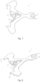
- Figures 7 and 8 are respectively a top view and a perspective view of an anchor according to the present invention.
- Figures 1 and 2 show an escape wheel 1 for use in an escapement of a watch movement (not shown), such as disclosed in WO 2019/156552 .
- the escape wheel is made from a brittle material, e.g. silicon, e.g. etched by means of DRIE from a 100 silicon wafer, and comprises, along its circumference, a plurality of teeth 2 that in an escapement cooperate with anchor teeth on an anchor or on an oscillator.
- the anchor teeth are controlled by the oscillator to alternately block and release the teeth of the escape wheel, in a manner known in itself and not specific to the present invention.
- the escape wheel has at least three cantilevered and resilient arms, more specifically six arms 3 in the example shown in Figure 1 , and a central opening 4 for receiving a shaft (not shown), which central opening is defined by the distal ends 5 of the cantilevered and resilient arms, i.e. the spaces between the distal ends of the resilient arms are free from rigid positioning elements, and the like.
- the distal ends of the resilient arms are arc-shaped and thus define an at least substantially round opening for a round shaft.
- the arms 3 are evenly distributed around the central opening 4 and extend primarily tangentially. Further, the arms are arranged in pairs of arms working in opposite directions at equal force. More specifically, the arms of the different pairs exert slightly different forces as a result of the anisotropy of the material (the arms is one pair will be slightly stiffer or less stiff than the arms in another pair), but the opposing arms in a pair exert the same force in opposite direction, providing effective elastic averaging and ensuring that, when a shaft is inserted in the central opening, the escape wheel is concentric with the (imaginary) center line of the shaft.
- the escape wheel comprises rigid structures 6 located radially behind the resilient arms 3 defining the central opening 4, providing stops for the resilient arms, in particular to prevent failure during insertion of a shaft or when a severe shock occurs.
- Figure 2 shows a similar embodiment, albeit with three resilient arms 3 instead of six.
- the thickness of the arms is slightly different (not discernible from the present drawing) to ensure that the bending stiffness of all three arms is equal.
- Figures 3 and 4 show embodiment provided with both a rigid structure and a further resilient arms, located radially behind the central resilient arms defining the central opening. These configurations provide, in addition to the tops, ⁇ stiffness ramping', e.g. low stiffness during insertion of a shaft and higher stiffness and thus stronger elastic averaging and clamping after the shaft has been installed.
- ⁇ stiffness ramping' e.g. low stiffness during insertion of a shaft and higher stiffness and thus stronger elastic averaging and clamping after the shaft has been installed.
- Figure 5 shows an embodiment wherein one of the arms 3 comprises a protrusion 8 to provide a form fit between that arm 3 and an inserted shaft.
- the part such as the escape wheel discussed above, provides self-alignment, for both concentricity and tilt, reduced sensitivity to fabrication errors compared with configuration comprising e.g. one flexure urging a shaft against two rigid points, and simplified assembly.
- the reaction force of the arms (flexures) on the shaft can be designed high enough so that no glue is required.
- the advantages, in particular the concentricity resulting from elastic averaging and suppression of tilt, provided by the present invention are particularly pronounced in escapements wherein the amplitude of the anchor teeth is at least substantially equal to the amplitude of the oscillator and/or in escapements with low torque escape wheels, such as escape wheels having a torque of less than 300 nanoNewtonmeter, less than 200 nNm or even less than 150 nNm.
- Torque is typically generated by a main spring and transmitted via a gear train.
- the distal ends can be configured to define a triangular opening for a triangular shaft or to define e.g. a square or hexagonal opening.
- elastic averaging in accordance with the present invention can be applied in other horological parts, such as a "Swiss" anchor, comprising anchor teeth 9, a fork slot 10, and guard pin 11.
Landscapes
- Physics & Mathematics (AREA)
- General Physics & Mathematics (AREA)
- Micromachines (AREA)
Priority Applications (1)
| Application Number | Priority Date | Filing Date | Title |
|---|---|---|---|
| EP23176839.1A EP4471505A1 (de) | 2023-06-01 | 2023-06-01 | Mechanisches teil für uhrwerk einer armbanduhr |
Applications Claiming Priority (1)
| Application Number | Priority Date | Filing Date | Title |
|---|---|---|---|
| EP23176839.1A EP4471505A1 (de) | 2023-06-01 | 2023-06-01 | Mechanisches teil für uhrwerk einer armbanduhr |
Publications (1)
| Publication Number | Publication Date |
|---|---|
| EP4471505A1 true EP4471505A1 (de) | 2024-12-04 |
Family
ID=86657291
Family Applications (1)
| Application Number | Title | Priority Date | Filing Date |
|---|---|---|---|
| EP23176839.1A Pending EP4471505A1 (de) | 2023-06-01 | 2023-06-01 | Mechanisches teil für uhrwerk einer armbanduhr |
Country Status (1)
| Country | Link |
|---|---|
| EP (1) | EP4471505A1 (de) |
Citations (16)
| Publication number | Priority date | Publication date | Assignee | Title |
|---|---|---|---|---|
| EP1331528A2 (de) | 2002-01-29 | 2003-07-30 | Franck Muller-Watchland SA | Anker einer Uhrenhemmung |
| US20080112274A1 (en) * | 2006-11-09 | 2008-05-15 | Eta Sa Manufacture Horlogere Suisse | Assembly element including fork shaped elastic structures and timepiece including the same |
| EP1991916A1 (de) | 2006-02-28 | 2008-11-19 | Nivarox-FAR S.A. | Mikromechanisches stück mit formöffnung zur assemblierung auf einer spindel |
| US7926355B2 (en) * | 2008-04-21 | 2011-04-19 | Rolex S.A. | Micromechanical part with an opening for fastening to a spindle |
| US20110103200A1 (en) * | 2009-10-29 | 2011-05-05 | Nivarox-Far S.A. | System for securing a part without driving in or bonding |
| US20120090933A1 (en) * | 2010-10-15 | 2012-04-19 | Eta Sa Manufacture Horlogere Suisse | Assembly of a part that has no plastic domain |
| US20170176935A1 (en) * | 2015-12-17 | 2017-06-22 | Nivarox-Far S.A. | Composite component with stressed resilient means |
| US20180150029A1 (en) * | 2016-11-29 | 2018-05-31 | Seiko Epson Corporation | Mechanical component, timepiece, manufacturing method of mechanical component, and manufacturing method of timepiece |
| EP3382472A1 (de) * | 2017-03-30 | 2018-10-03 | Rolex Sa | Führungslager einer unruhwelle einer uhr |
| EP3418815A2 (de) | 2017-05-16 | 2018-12-26 | Seiko Epson Corporation | Mechanisches teil, uhr und verfahren zur herstellung eines mechanischen teils |
| WO2019156552A1 (en) | 2018-02-06 | 2019-08-15 | Flexous Mechanisms Ip B.V. | Mechanical watch oscillator |
| CH716511A2 (fr) * | 2019-08-16 | 2021-02-26 | Nivarox Sa | Organe de maintien élastique d'un composant d'horlogerie sur un élément de support. |
| US20210149343A1 (en) | 2019-11-19 | 2021-05-20 | Seiko Epson Corporation | Watch component and watch |
| CH717005A2 (de) | 2019-12-18 | 2021-06-30 | Horage S A | Ankerhemmung, Anker und Hemmungsrad. |
| US20220283544A1 (en) * | 2019-08-16 | 2022-09-08 | Nivarox-Far S.A. | Method for producing an assembly of an elastic holding member-timepiece component assembly with a support element |
| FR3128953A1 (fr) * | 2021-11-05 | 2023-05-12 | Silmach | Procédé d’assemblage d’une première pièce avec une deuxième pièce en silicium |
-
2023
- 2023-06-01 EP EP23176839.1A patent/EP4471505A1/de active Pending
Patent Citations (16)
| Publication number | Priority date | Publication date | Assignee | Title |
|---|---|---|---|---|
| EP1331528A2 (de) | 2002-01-29 | 2003-07-30 | Franck Muller-Watchland SA | Anker einer Uhrenhemmung |
| EP1991916A1 (de) | 2006-02-28 | 2008-11-19 | Nivarox-FAR S.A. | Mikromechanisches stück mit formöffnung zur assemblierung auf einer spindel |
| US20080112274A1 (en) * | 2006-11-09 | 2008-05-15 | Eta Sa Manufacture Horlogere Suisse | Assembly element including fork shaped elastic structures and timepiece including the same |
| US7926355B2 (en) * | 2008-04-21 | 2011-04-19 | Rolex S.A. | Micromechanical part with an opening for fastening to a spindle |
| US20110103200A1 (en) * | 2009-10-29 | 2011-05-05 | Nivarox-Far S.A. | System for securing a part without driving in or bonding |
| US20120090933A1 (en) * | 2010-10-15 | 2012-04-19 | Eta Sa Manufacture Horlogere Suisse | Assembly of a part that has no plastic domain |
| US20170176935A1 (en) * | 2015-12-17 | 2017-06-22 | Nivarox-Far S.A. | Composite component with stressed resilient means |
| US20180150029A1 (en) * | 2016-11-29 | 2018-05-31 | Seiko Epson Corporation | Mechanical component, timepiece, manufacturing method of mechanical component, and manufacturing method of timepiece |
| EP3382472A1 (de) * | 2017-03-30 | 2018-10-03 | Rolex Sa | Führungslager einer unruhwelle einer uhr |
| EP3418815A2 (de) | 2017-05-16 | 2018-12-26 | Seiko Epson Corporation | Mechanisches teil, uhr und verfahren zur herstellung eines mechanischen teils |
| WO2019156552A1 (en) | 2018-02-06 | 2019-08-15 | Flexous Mechanisms Ip B.V. | Mechanical watch oscillator |
| CH716511A2 (fr) * | 2019-08-16 | 2021-02-26 | Nivarox Sa | Organe de maintien élastique d'un composant d'horlogerie sur un élément de support. |
| US20220283544A1 (en) * | 2019-08-16 | 2022-09-08 | Nivarox-Far S.A. | Method for producing an assembly of an elastic holding member-timepiece component assembly with a support element |
| US20210149343A1 (en) | 2019-11-19 | 2021-05-20 | Seiko Epson Corporation | Watch component and watch |
| CH717005A2 (de) | 2019-12-18 | 2021-06-30 | Horage S A | Ankerhemmung, Anker und Hemmungsrad. |
| FR3128953A1 (fr) * | 2021-11-05 | 2023-05-12 | Silmach | Procédé d’assemblage d’une première pièce avec une deuxième pièce en silicium |
Similar Documents
| Publication | Publication Date | Title |
|---|---|---|
| KR101245025B1 (ko) | 조립체 요소 및 이를 포함하는 시계 | |
| JP5175523B2 (ja) | フォーク形状弾性構造体を備える組立要素およびそれを備える時計 | |
| JP5235869B2 (ja) | 時計ムーブメントのひげぜんまい−ひげ玉組立体 | |
| US9411314B2 (en) | Integral assembly of a hairspring and a collet | |
| US7575369B2 (en) | Assembly element including two series of elastic structures and timepiece fitted with the same | |
| JP6578086B2 (ja) | 組み込み部材を収容するための時計部品 | |
| US5357489A (en) | Timepiece provided with driving means formed by a piezo-electric motor | |
| EP3418815B1 (de) | Mechanisches teil, uhr und verfahren zur herstellung eines mechanischen teils | |
| US12276942B2 (en) | Timepiece display mechanism | |
| CN113608423B (zh) | 钟表分度元件 | |
| EP4471505A1 (de) | Mechanisches teil für uhrwerk einer armbanduhr | |
| HK40120030A (zh) | 用於时计的轴承 | |
| TWI893489B (zh) | 彈性緊固元件、彈性緊固元件與時計部件組件、用於時計的鐘錶機芯的裝配、鐘錶機芯、時計、及用於執行該裝配的方法 | |
| TWI910482B (zh) | 用於將時計部件附接於支撐元件的彈性固持構件、組件、總成、時計機芯、時計及製造總成的方法 | |
| JP7745036B2 (ja) | 計時器用ベアリング | |
| EP4564104A1 (de) | Mechanische uhr | |
| CN115685719A (zh) | 对两个钟表部件进行机械连接的环 | |
| HK1120872B (en) | Assembly element including fork shaped elastic structures and timepiece including the same | |
| HK40077568A (en) | Timepiece display mechanism | |
| HK40086112A (zh) | 表盘、包括这种表盘的手表及将表盘安装在手表中的方法 | |
| HK1121818B (en) | Assembly element including superposed strip shaped elastic structures and timepiece fitted with the same | |
| HK1132050B (en) | Micromechanical piece with form opening for assembly on a spindle | |
| HK1132050A1 (en) | Micromechanical piece with form opening for assembly on a spindle |
Legal Events
| Date | Code | Title | Description |
|---|---|---|---|
| PUAI | Public reference made under article 153(3) epc to a published international application that has entered the european phase |
Free format text: ORIGINAL CODE: 0009012 |
|
| STAA | Information on the status of an ep patent application or granted ep patent |
Free format text: STATUS: THE APPLICATION HAS BEEN PUBLISHED |
|
| AK | Designated contracting states |
Kind code of ref document: A1 Designated state(s): AL AT BE BG CH CY CZ DE DK EE ES FI FR GB GR HR HU IE IS IT LI LT LU LV MC ME MK MT NL NO PL PT RO RS SE SI SK SM TR |
|
| STAA | Information on the status of an ep patent application or granted ep patent |
Free format text: STATUS: REQUEST FOR EXAMINATION WAS MADE |
|
| 17P | Request for examination filed |
Effective date: 20250604 |