EP4472025A1 - Circuit de gestion d'alimentation électrique, module de fonction, dispositif de fonctionnement autonome et système de commande - Google Patents
Circuit de gestion d'alimentation électrique, module de fonction, dispositif de fonctionnement autonome et système de commande Download PDFInfo
- Publication number
- EP4472025A1 EP4472025A1 EP23746404.5A EP23746404A EP4472025A1 EP 4472025 A1 EP4472025 A1 EP 4472025A1 EP 23746404 A EP23746404 A EP 23746404A EP 4472025 A1 EP4472025 A1 EP 4472025A1
- Authority
- EP
- European Patent Office
- Prior art keywords
- unit
- switch
- operation device
- autonomous operation
- voltage
- Prior art date
- Legal status (The legal status is an assumption and is not a legal conclusion. Google has not performed a legal analysis and makes no representation as to the accuracy of the status listed.)
- Pending
Links
Images


Classifications
-
- B—PERFORMING OPERATIONS; TRANSPORTING
- B60—VEHICLES IN GENERAL
- B60L—PROPULSION OF ELECTRICALLY-PROPELLED VEHICLES; SUPPLYING ELECTRIC POWER FOR AUXILIARY EQUIPMENT OF ELECTRICALLY-PROPELLED VEHICLES; ELECTRODYNAMIC BRAKE SYSTEMS FOR VEHICLES IN GENERAL; MAGNETIC SUSPENSION OR LEVITATION FOR VEHICLES; MONITORING OPERATING VARIABLES OF ELECTRICALLY-PROPELLED VEHICLES; ELECTRIC SAFETY DEVICES FOR ELECTRICALLY-PROPELLED VEHICLES
- B60L58/00—Methods or circuit arrangements for monitoring or controlling batteries or fuel cells, specially adapted for electric vehicles
- B60L58/10—Methods or circuit arrangements for monitoring or controlling batteries or fuel cells, specially adapted for electric vehicles for monitoring or controlling batteries
-
- H—ELECTRICITY
- H02—GENERATION; CONVERSION OR DISTRIBUTION OF ELECTRIC POWER
- H02J—ELECTRIC POWER NETWORKS; CIRCUIT ARRANGEMENTS OR SYSTEMS FOR SUPPLYING OR DISTRIBUTING ELECTRIC POWER; SYSTEMS FOR STORING ELECTRIC ENERGY
- H02J7/00—Circuit arrangements for charging or discharging batteries or for supplying loads from batteries
- H02J7/865—Battery or charger load switching, e.g. concurrent charging and load supply
-
- B—PERFORMING OPERATIONS; TRANSPORTING
- B60—VEHICLES IN GENERAL
- B60L—PROPULSION OF ELECTRICALLY-PROPELLED VEHICLES; SUPPLYING ELECTRIC POWER FOR AUXILIARY EQUIPMENT OF ELECTRICALLY-PROPELLED VEHICLES; ELECTRODYNAMIC BRAKE SYSTEMS FOR VEHICLES IN GENERAL; MAGNETIC SUSPENSION OR LEVITATION FOR VEHICLES; MONITORING OPERATING VARIABLES OF ELECTRICALLY-PROPELLED VEHICLES; ELECTRIC SAFETY DEVICES FOR ELECTRICALLY-PROPELLED VEHICLES
- B60L1/00—Supplying electric power to auxiliary equipment of vehicles
-
- G—PHYSICS
- G05—CONTROLLING; REGULATING
- G05F—SYSTEMS FOR REGULATING ELECTRIC OR MAGNETIC VARIABLES
- G05F1/00—Automatic systems in which deviations of an electric quantity from one or more predetermined values are detected at the output of the system and fed back to a device within the system to restore the detected quantity to its predetermined value or values, i.e. retroactive systems
- G05F1/10—Regulating voltage or current
- G05F1/46—Regulating voltage or current wherein the variable actually regulated by the final control device is DC
- G05F1/462—Regulating voltage or current wherein the variable actually regulated by the final control device is DC as a function of the requirements of the load, e.g. delay, temperature, specific voltage/current characteristic
-
- H—ELECTRICITY
- H02—GENERATION; CONVERSION OR DISTRIBUTION OF ELECTRIC POWER
- H02J—ELECTRIC POWER NETWORKS; CIRCUIT ARRANGEMENTS OR SYSTEMS FOR SUPPLYING OR DISTRIBUTING ELECTRIC POWER; SYSTEMS FOR STORING ELECTRIC ENERGY
- H02J3/00—Circuit arrangements for AC mains or AC distribution networks
- H02J3/001—Arrangements for handling faults or abnormalities, e.g. emergencies or contingencies
-
- H—ELECTRICITY
- H02—GENERATION; CONVERSION OR DISTRIBUTION OF ELECTRIC POWER
- H02J—ELECTRIC POWER NETWORKS; CIRCUIT ARRANGEMENTS OR SYSTEMS FOR SUPPLYING OR DISTRIBUTING ELECTRIC POWER; SYSTEMS FOR STORING ELECTRIC ENERGY
- H02J7/00—Circuit arrangements for charging or discharging batteries or for supplying loads from batteries
- H02J7/855—Circuit arrangements for charging or discharging batteries or for supplying loads from batteries with circuits adapted for supplying loads from the battery
-
- H—ELECTRICITY
- H02—GENERATION; CONVERSION OR DISTRIBUTION OF ELECTRIC POWER
- H02J—ELECTRIC POWER NETWORKS; CIRCUIT ARRANGEMENTS OR SYSTEMS FOR SUPPLYING OR DISTRIBUTING ELECTRIC POWER; SYSTEMS FOR STORING ELECTRIC ENERGY
- H02J7/00—Circuit arrangements for charging or discharging batteries or for supplying loads from batteries
- H02J7/90—Regulation of charging or discharging current or voltage
- H02J7/96—Regulation of charging or discharging current or voltage in response to battery voltage
-
- H—ELECTRICITY
- H02—GENERATION; CONVERSION OR DISTRIBUTION OF ELECTRIC POWER
- H02J—ELECTRIC POWER NETWORKS; CIRCUIT ARRANGEMENTS OR SYSTEMS FOR SUPPLYING OR DISTRIBUTING ELECTRIC POWER; SYSTEMS FOR STORING ELECTRIC ENERGY
- H02J9/00—Circuit arrangements for emergency or stand-by power supply, e.g. for emergency lighting
- H02J9/04—Circuit arrangements for emergency or stand-by power supply, e.g. for emergency lighting in which the distribution system is disconnected from the normal source and connected to a standby source
- H02J9/06—Circuit arrangements for emergency or stand-by power supply, e.g. for emergency lighting in which the distribution system is disconnected from the normal source and connected to a standby source with automatic change-over, e.g. UPS systems
-
- H—ELECTRICITY
- H02—GENERATION; CONVERSION OR DISTRIBUTION OF ELECTRIC POWER
- H02M—APPARATUS FOR CONVERSION BETWEEN AC AND AC, BETWEEN AC AND DC, OR BETWEEN DC AND DC, AND FOR USE WITH MAINS OR SIMILAR POWER SUPPLY SYSTEMS; CONVERSION OF DC OR AC INPUT POWER INTO SURGE OUTPUT POWER; CONTROL OR REGULATION THEREOF
- H02M3/00—Conversion of DC power input into DC power output
- H02M3/02—Conversion of DC power input into DC power output without intermediate conversion into AC
- H02M3/04—Conversion of DC power input into DC power output without intermediate conversion into AC by static converters
-
- A—HUMAN NECESSITIES
- A01—AGRICULTURE; FORESTRY; ANIMAL HUSBANDRY; HUNTING; TRAPPING; FISHING
- A01D—HARVESTING; MOWING
- A01D34/00—Mowers; Mowing apparatus of harvesters
- A01D34/006—Control or measuring arrangements
- A01D34/008—Control or measuring arrangements for automated or remotely controlled operation
-
- B—PERFORMING OPERATIONS; TRANSPORTING
- B60—VEHICLES IN GENERAL
- B60L—PROPULSION OF ELECTRICALLY-PROPELLED VEHICLES; SUPPLYING ELECTRIC POWER FOR AUXILIARY EQUIPMENT OF ELECTRICALLY-PROPELLED VEHICLES; ELECTRODYNAMIC BRAKE SYSTEMS FOR VEHICLES IN GENERAL; MAGNETIC SUSPENSION OR LEVITATION FOR VEHICLES; MONITORING OPERATING VARIABLES OF ELECTRICALLY-PROPELLED VEHICLES; ELECTRIC SAFETY DEVICES FOR ELECTRICALLY-PROPELLED VEHICLES
- B60L2200/00—Type of vehicles
- B60L2200/40—Working vehicles
-
- B—PERFORMING OPERATIONS; TRANSPORTING
- B60—VEHICLES IN GENERAL
- B60R—VEHICLES, VEHICLE FITTINGS, OR VEHICLE PARTS, NOT OTHERWISE PROVIDED FOR
- B60R25/00—Fittings or systems for preventing or indicating unauthorised use or theft of vehicles
- B60R25/20—Means to switch the anti-theft system on or off
-
- B—PERFORMING OPERATIONS; TRANSPORTING
- B60—VEHICLES IN GENERAL
- B60R—VEHICLES, VEHICLE FITTINGS, OR VEHICLE PARTS, NOT OTHERWISE PROVIDED FOR
- B60R25/00—Fittings or systems for preventing or indicating unauthorised use or theft of vehicles
- B60R25/30—Detection related to theft or to other events relevant to anti-theft systems
- B60R25/33—Detection related to theft or to other events relevant to anti-theft systems of global position, e.g. by providing GPS coordinates
-
- G—PHYSICS
- G05—CONTROLLING; REGULATING
- G05D—SYSTEMS FOR CONTROLLING OR REGULATING NON-ELECTRIC VARIABLES
- G05D1/00—Control of position, course, altitude or attitude of land, water, air or space vehicles, e.g. using automatic pilots
- G05D1/60—Intended control result
-
- G—PHYSICS
- G05—CONTROLLING; REGULATING
- G05D—SYSTEMS FOR CONTROLLING OR REGULATING NON-ELECTRIC VARIABLES
- G05D2105/00—Specific applications of the controlled vehicles
- G05D2105/15—Specific applications of the controlled vehicles for harvesting, sowing or mowing in agriculture or forestry
-
- H—ELECTRICITY
- H02—GENERATION; CONVERSION OR DISTRIBUTION OF ELECTRIC POWER
- H02J—ELECTRIC POWER NETWORKS; CIRCUIT ARRANGEMENTS OR SYSTEMS FOR SUPPLYING OR DISTRIBUTING ELECTRIC POWER; SYSTEMS FOR STORING ELECTRIC ENERGY
- H02J2207/00—Details of circuit arrangements for charging or discharging batteries or supplying loads from batteries
- H02J2207/20—Charging or discharging characterised by the power electronics converter
Definitions
- Embodiments of the present invention provide a control method, system, autonomous operation device, and medium for autonomous operation device to solve the problem of weak anti-theft ability of autonomous operation robots and improve the anti-theft ability of autonomous operation devices.
- an embodiment of the present invention provides a control method for autonomous operation device, comprising: obtaining motion data of a target object; obtaining the position information of the target object based on the motion data of the target object; generating a security status information of the target object based on the position information of the target object.
- an embodiment of the present invention provides an autonomous operation device, comprising a control system of the autonomous operation device.
- the present invention provides a power supply management circuit, function module, autonomous operation device, and a control system to solve the problem of high power consumption of autonomous operation device and the influence on the standby time of the anti-theft function of the autonomous operation device.
- an embodiment of the present invention provides a power supply management circuit, including: a switch unit, a first voltage reduction unit, a second voltage reduction unit and a control unit; the switch unit being connected to the battery and used to turn on or off the path between the battery and the load.
- the power supply management circuit includes a first state and a second state;
- the first voltage reduction unit is connected to the switching unit, and is used to convert the voltage of the battery into the voltage required by the load in the first state and supply power to the load;
- the second voltage reducing unit is respectively connected to the switching unit and the control unit.
- the second voltage reduction unit is used to convert the voltage of the battery into the voltage required by the load according to the first control instruction of the control unit in the second state, and supply power to the load to solve the technical problem.
- An embodiment of the present invention provides a function module, including the power supply management circuit described above.
- an embodiment of the present invention provides a control system for an autonomous operation device, wherein the control system of the autonomous operation device is powered by any of the power supply management circuits described in the first aspect;
- the control system of the autonomous operation device includes a sensor, used to obtain motion data of the autonomous operation device; a positioning unit, used to obtain the position information of the autonomous operation device based on the motion data of the autonomous operation device; a state information generation unit, used to generate security status information of the autonomous operation device based on its position information.
- an embodiment of the present invention provides an autonomous operation device, comprising: any one of the power supply management circuit in the first aspect or the function module proposed in the second aspect, or the control system, battery, and load of the autonomous operation device proposed in the third aspect;
- the battery is connected to the power input interface of the power supply management circuit, and the load is connected to the first power output interface and the second power output interface of the power supply management circuit.
- the battery is used to supply power to the load through the power supply management circuit.
- the load includes the control system of the autonomous operation device.
- Figure 1 is a schematic diagram of the structure of a power supply management circuit provided in an embodiment of the present invention.
- the power supply management circuit provided in the embodiment of the present invention includes: a switch unit 1, a first voltage reduction unit 2, a second voltage reduction unit 3, and a control unit 4; the switch unit 1 is connected to the battery 10, and is used to turn on or turn off the path between the battery 10 and the load 20; When the switch unit 1 is turned on, the power supply management circuit includes a first state and a second state.
- the first voltage reduction unit 2 is connected to the switch unit 1.
- the first voltage reduction unit 2 is used to convert the voltage of the battery 10 into the voltage required by the load 20 in the first state and supply power to the load 20;
- the second voltage reduction unit 3 is connected to the switch unit1 and the control unit 4 respectively.
- the second voltage reduction unit 3 is used to convert the voltage of the battery 10 into the voltage required by the load 20 according to the first control instruction of the control unit 4 in the second state, and supply power to the load 20.
- the switch unit 1 can be turned on or off.
- battery 10 stops outputting electricity.
- the switch unit 1 is turned on, battery 10 supplies power to the load 20 through the power supply management circuit.
- the power supply management circuit includes a first state and a second state.
- the first state can be set to require a smaller current, such as in a sleep or standby state;
- the second state requires a larger current, for example, in an activated or operating state.
- the static current consumption of the first voltage reduction unit is very low, ranging from a few microamperes to over a dozen microampere levels, but the maximum output current of the first voltage reduction unit can only be within 100 milliamperes.
- the static current consumption of the second voltage reduction unit ranges from dozens to hundreds of microamperes, but it can drive loads of several amperes when enabled.
- the communication unit has an instantaneous peak current of 1-2 amperes.
- the first voltage reduction unit 2 will be powered on after the switch unit 1 is turned on.
- the voltage signal output by the first voltage reduction unit 2 has a smaller voltage amplitude, which can stably output voltage to the load 20 in the first state, making the power supply management circuit have lower power in the first state.
- the control unit 4 is in the second state, a first control instruction is generated, the first control instruction can be a level signal, such as a high-level signal or a low-level signal.
- the second voltage reduction unit 3 is turned on and converts the voltage of the battery 10 into the voltage required by the load 20 according to the first control instruction of the control unit 4, and supplies power to the load 20, so that the voltage output by the power supply management circuit can meet the electricity demand of the load 20 in the second state.
- the power supply management circuit provided in this embodiment meets its low-power requirements by setting to be in the first state, converting the voltage of the battery to the voltage required by the load through the first voltage reduction unit and supplying power to the load; In the second state, the voltage of the battery is converted into the voltage required by the load through the second voltage reduction unit according to the first control instruction of the control unit, and power is supplied to the load, which meet the high-power demand of the load, and realize low-power consumption power supply for the power supply management circuit.
- Figure 2 is a schematic diagram of the structure of another power supply management circuit provided by an embodiment of the present embodiment.
- the power supply management circuit provided by the embodiment of the present invention may further include a gating unit 5.
- the input end of the gating unit 5 is connected to the output end of the second voltage reduction unit 3, and the output end of the gating unit 5 is connected to the output end of the first voltage reduction unit 2.
- the gating unit 5 is used to select the first voltage reduction unit 2 to output electrical signal in the first state, and in the second state, select the second voltage reduction unit 3 to output voltage.
- the first state can be a sleep state, for example, it is a sleep state when the autonomous operation device is in a charging or standby state.
- control unit 4 is in low-power mode, retaining only basic control function while all other function modules are turned off to reduce the power consumption of the power supply management circuit and load 20.
- the gating unit 5 controls the first voltage reduction unit 2to output the voltage signal to the output interface of the power supply management circuit, so as to reduce the voltage of the battery 10 to the power supply voltage through the first voltage reduction unit 2, to supply power to the load 20.
- the second state can be an activated state.
- the control unit 4 In the activated state, the control unit 4 is in the normal power consumption mode, and other function modules work to control the execution of each functional action.
- the gating unit 5 controls the second voltage reduction unit 3 to output the voltage signal to the output interface of the power supply management circuit, in order to reduce the voltage of battery 10 to the voltage of the power supply through the second voltage reduction unit 3 and supply power to load 20.
- the gating unit 5 selects the first voltage reduction unit 2 or the second voltage reduction unit 3 to output electrical energy to the load 20, so that the first voltage reduction unit 2 and the second voltage reduction unit 3 can select one of them to supply power to the load 20 in the first state and the second state, respectively, in the first state, the first voltage reduction unit 2 can supply power to the load 20, and in the second state, the second voltage reduction unit 3 can supply power to the load 20. Since the first voltage reduction unit 2 has low load capacity but low static current, the second voltage reduction unit 3 has strong load capacity but high static current. In the first state, the first voltage reduction unit 2 supplies power to the load 20 with low static current and low power consumption, reducing the power loss of the power supply management circuit. In the second state, the power is supplied to the load 20 through the second voltage reduction unit 3 to meet the power supply requirement of the load.
- Figure 3 is a schematic diagram of the structure of another power supply management circuit provided by an embodiment of the present invention.
- the gating unit 5 provided in the embodiment of the present invention turns on or turns off according to the voltage difference between the output end of the second voltage reduction unit 3 and the output end of the first voltage reduction unit 2, to select the first voltage reduction unit 2 to output voltage or the second voltage reduction unit 3 to output voltage.
- the gating unit 5 may include a first input diode D1 and a second input diode D2.
- the anode of the first input diode D 1 is connected to the output end of the second voltage reduction unit 3
- the anode of the second input diode D2 is connected to the output end of the first voltage reduction unit 2
- the cathode of the second input diode D2 is connected to the cathode of the first input diode D 1, which is used as the output end connection of the gating unit 5.
- the first input diode D1 When the electrical signal output from the output end of the second voltage reduction unit 3 is greater than the electrical signal output from the output end of the first voltage reduction unit 2, the first input diode D1 is turned on, and the voltage at the output end of the gating unit 5 is the electrical signal of the second voltage reduction unit 3 with a higher voltage.
- the output end of the gating unit 5 selects the second voltage reduction unit 3 to output the electrical signal.
- the first input diode D 1 is cut off, the second input diode D2 is turned on, and the voltage at the output end of the gating unit 5 is the electrical signal of the first voltage reduction unit 2 with a higher voltage, the output end of the gating unit 5 selects the first voltage reduction unit 2 to output the electrical signal.
- Figure 4 is a schematic diagram of the structure of another power supply management circuit provided by an embodiment of the present invention.
- the control end of the gating unit 5 provided in the embodiment of the present invention is connected to the communication control end 43 of the control unit 4;
- the gating unit 5 is used to select the first voltage reduction unit 2 or the second voltage reduction unit 3 to output the electrical signal according to the gating control instruction output by the control unit 4.
- the gating control instruction can be a control signal that controls the gating unit 5 to turn on or off.
- Control unit 4 can output gating control instructions according to the communication control end 43 of control unit 4.
- the gating unit 5 selects the first voltage reduction unit 2 or the second voltage reduction unit 3 to output the electrical signal according to the gating control instruction output by the control unit 4, so that the control unit 4 can select one of them to supply power to the load 20 in the first state or the second state, respectively.
- the first voltage reduction unit 2 can supply power to the load 20, and in the second state, the second voltage reduction unit 3 can supply power to the load 20, avoiding increasing the power loss of the first voltage reduction unit 2 and further reducing the power loss of the power supply management circuit due to the large current output to the load 20 by the first voltage reduction unit 2in the second state.
- Figure 5 is a schematic diagram of the structure of another power supply management circuit provided by an embodiment of the present invention.
- the power supply management circuit provided by the embodiment of the present invention may further include: a power input interface 101, a first power output interface 102, and a second power output interface 103; the power input interface 101 is connected to the battery 10 and the input end of the switch unit 1, and the first power output interface 102 is connected to the output end of the first voltage reduction unit 2;
- the first power output interface 102 is used to constantly output voltage;
- the second power output interface 103 is connected to the output end of the gating unit 5 and the output end of the second voltage reduction unit 3;
- the second power output end is used to output voltage from the second voltage reduction unit 3 in the second state and output voltage from the first voltage reduction unit 2 in the first state.
- the power input interface 101 can be connected to the battery 10 to input the voltage signal of the battery 10 to the power supply management circuit.
- the first power output interface 102 is connected to the output end of the first voltage reduction unit 2.
- the first power output interface 102 can continuously output a voltage signal with a lower voltage, which is used to supply power to the load 20requiring continuous power supply in the first state.
- the second power output interface 103 is connected to the second voltage reduction unit 3.
- the second power output interface 103 outputs an electrical signal from the second voltage reduction unit 3 in the second state through the gating unit 5, and outputs an electrical signal from the first voltage reduction unit 2 in the first state.
- Load 20 requiring high-power operation can be connected to the second power output interface 103.
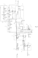
- Figure 6 is a schematic diagram of the structure of another power supply management circuit provided by an embodiment of the present invention.
- the switch unit 1 provided by the embodiment of the present invention may include: a first switch Q4 and a second switch Q6;
- the first end of the first switch Q4 is used as the input end of the switch unit 1, the second end of the first switch Q4 is used as the output end of the switch unit 1, the control end of the first switch Q4 is connected to the first end of the second switch Q6, the second end of the second switch Q6 is grounded, and the control end of the second switch Q6 is connected to the control unit 4;
- the control end of the second switch Q6 is used as the control end of switch unit 1.
- control unit 4 may include a main control module of the autonomous operation device or a controller of the power supply management circuit.
- the control signal output from the first output interface 41 of the control unit 4 is input to the control end of the second switch Q6 to control the first end and second end of the second switch Q6 to be turned on.
- the first end of the second switch Q6 outputs a low-level signal to the control end of the first switchQ6, causing the first end and second end of the first switch Q4 to be turned on. Due to the connection between battery 10 and the input end of the switch unit 1, the first end of the first switch Q4 is connected to the input end of the switch unit 1, allowing battery 10 to supply power to load 20 through the power supply management circuit.
- the first voltage reduction unit 2 provided by the present invention includes a stabilivolt diode D3 and an LDO chip U3.
- the cathode of stabilivolt diode D3 as an input end of first voltage reduction unit 2 is connected to the output end of switch unit 1.
- the anode of stabilivolt diode D3 is connected to the input end of LDO chip U3, and the output end of LDO chip U3 is used as the output end of the first voltage reduction unit 2.
- the output end of LDO chip U3 is connected to the load 20.
- the output end of LDO chip U3 is used to convert the voltage signal of battery 10 into the voltage required by load 20 and supply power to load 20.
- the stabilivolt diode D3 plays a stabilizing role and is used to clamp the voltage of battery 10 through the stabilivolt diode D3. For example, if the maximum input voltage of the first voltage reduction unit 2 is 30V, while the voltage of the stabilivolt diode D3 can be 12V, then if the anode input voltage of the stabilivolt diode D3 is 42V, it will not cause damage to the first voltage reduction unit 2. If the power supply management circuit loses control, the power supply management circuit will also power down when the battery voltage is lower than the voltage of the stabilivolt diode D3, without completely discharging the battery and damaging it.
- the LDO chip U3 plays the role of reducing voltage. For example, the output voltage of the LDO chip U3 can be 4V
- Figure 7 is a schematic diagram of the structure of another power supply management circuit provided by an embodiment of the present invention.
- the power supply management circuit provided by the embodiment of the present invention may further include: a self-locking unit 6, the input end of the self-locking unit 6 is connected to the output end 21 of the first voltage reduction unit 2, and the output end of the self-locking unit 6 is connected to the control end of the switch unit 1.
- the self-locking unit 6 is used to control the switch unit 1 to maintain a turned-on state according to the voltage output by the first voltage reduction unit 2.
- the voltage reduction unit 2 is powered on, and the self-locking unit 6 is connected to the output end 21 of the first voltage reduction unit 2.
- the self-locking unit 6 can output the voltage output by the first voltage reduction unit 2 to the control end of the switch unit 1.
- the self-locking unit 6 can control the voltage output by the first voltage reduction unit Control switch unit 1 to maintain a turned-on state, so that the first power output interface 102 and the second power output interface 103 of the power supply management circuit can continually output voltage, easy to stabilize to supply power to the load 20.
- the self-locking unit 6 provided by the present invention embodiment includes a first resistor R17 and a first diode D61.
- the first end of the first resistor R17 is used as the input end of the self-locking unit 6, and the second end of the first resistor R17 is connected to the anode of the first diode D61.
- the cathode of the first diode D61 as the output end of the self-locking unit 6 is connected to the control end of the switch unit1.
- the first resistor R17 plays a role of limiting current
- the first diode D61 plays a role of preventing reverse connection.
- the eighth switch Q8 is not turned on, and thus the seventh switch Q7 is not turned on.
- the self-locking voltage passes through the first resistor R17 and the first diode D61 to the control end of the second switch Q6, thereby conducting the first and second ends of the second switch Q6, and then turning on the first switch Q4.
- the second voltage reduction unit 3 can include a DC-DC chip U4, the input endof the DC-DC chip U4is connected to the output end of the switch unit 1, the control end of the DC-DC chip U4 is connected to the control unit 4, and the output endof the DC-DC chip U4is connected to the load 20.
- the DC-DC chip U4 is used to reduce the voltage of the voltage signal of the battery 10 and supply power to the load 20 according to the DC-DC enable signal of the control unit 4.
- the DC-DC chip U4 can reduce the DC voltage signal of the battery 10, such as the DC 14 ⁇ 24V voltage signal, to the power supply voltage required for the load, such as the DC 3.8V.
- the power supply management circuit can also include: a sampling unit 7, the input end of the sampling unit 7 is connected to the output end of the switch unit 1, the output end of the sampling unit 7 is connected to the voltage sampling input end 44 of the control unit 4, and the control end of the sampling unit 7 is connected to the output end 31 of the second voltage reduction unit 3.
- the sampling unit 7 is used to collect the voltage amplitude of the power supply circuit of the battery 10 after passing through the switch unit 1 according to the control signal of the control end.
- sampling unit 7 can collect the voltage signal at the output end of switch unit 1 according to the control signal received at its control end.
- the output end 31 of the second voltage reduction unit 3 stops outputting voltage signals
- the control end of the sampling unit 7 stops sampling according to the voltage signal output from the output end 31 of the second voltage reduction unit 3, for example, a low-level signal is turned off.
- This setting can stop sampling in the first state, such as a sleep mode, further reducing the power loss of control unit 4.
- the sampling circuit is used to prevent battery damage caused by the battery voltage dropping below the safe voltage without shutting down, in order to improve the service life of the battery.
- the sampling unit 7 may include: a third switch Q5 and a first resistor network 71; the first end of the third switch Q5 is used as the input end of the sampling unit 7, the second end of the third switch Q5 is connected to the first end of the first resistor network, the second end of the first resistor network is used as the control end of the switch unit 1; the third end of the first resistor network 71 is electrical grounded; a fourth switch Q9 and a second resistor network 72; the first end of the second resistor network 72 is connected to the first end of the third switch Q5, the second end of the second resistor network 72 is connected to the control end of the third switch Q5, the third end of the second resistor 72 is connected to the first end of the fourth switch Q9, the control end of the fourth switch Q9 is used as the control end of the sampling unit 7; the second end of the fourth switch Q9 is electrical grounded.
- the first resistor network 71 and the second resistor network 72 play roles of dividing voltage, respectively.
- the control end of the fourth switch Q9 receives a high-level signal output from the second voltage reduction unit 3, the first end and the second end of the fourth switch Q9 are conducting, the second resistor network 72 divides the voltage signal of the battery 10, so that the voltage between the first terminal and the control terminal of the third switch Q5 is great than the turn-on voltage of the third switch Q5, to make the third switch Q5 turn on, the turning on of the third switch Q5 makes the voltage signal of the battery 10 divide via the first resistor network 71 and output to the control unit 4.
- the control end of the fourth switch Q9 When the control end of the fourth switch Q9 receives a low-level signal output from the second voltage reduction unit 3, the first end and the second end of the third switch Q5 are turned off, the loop where the second resistor network 72 locates is broken, to make the voltage between the first end and the control end of the third switch Q5 to be nearly zero, and less than the turn-on voltage of the third switch Q5, to make the third switch Q5 to be turned off.
- the turned off third switch Q5 makes the first resistor network 71 broke and the sampling unit 7 stop sampling.
- the gating unit 5 may include: a fifth switch Q2 and a sixth switch Q3; the first end of the fifth switch Q2 is used as the input end of the gating unit 5, the second end of the fifth switch Q2 is used as the output end 52 of the gating unit 5, the control end of the fifth switch Q2 is connected to the first end of the sixth switch Q3, the second end of the sixth switch Q3 is grounded, the control end of the sixth switch Q3 is used as the control end of the gating unit 5.
- control end of the sixth switch Q3 is used as the control end of the gating unit 5, which is connected to the communication control end 43 of the control unit 4.
- the sixth switch Q3 When the sixth switch Q3 outputs the electrical signal at the second voltage reduction unit 3, the sixth switch Q3 is turned on, to make the first end and the second end of the sixth switch Q3 turned on.
- shutdown unit 8 can include a seventh switch Q7 and an eighth switch Q8, the first end of seventh switch Q7 is used as the output end of shutdown unit 8, the second end of the seventh switch Q7 is grounded, the control end of the seventh switch Q7 is connected to the first end of the eighth switch Q8, the second end of the eighth Q8 is grounded, and the control end of the eighth switch Q8 is used as the input end of the shutdown unit 8.
- control end of the eighth switch Q8 of the shutdown unit 8 makes the first end and the second end of the eighth switch Q8 to be conducting according to the control signal of the control unit 4, further makes the control end of the seventh switch Q7 to input a low-level voltage, further makes the first end and second end of the seventh switch Q7 to be conducting, makes the self-locking unit 6 to input a low-level signal and exit the self-locking state.
- the control end of switch unit 1 inputs a low-level signal, causing switch unit 1 to turn off, thereby shutting down the power supply management circuit.
- Figure 8 is a schematic diagram of the structure of another power supply management circuit provided by an embodiment of the present invention.
- the power supply management circuit further comprises: a sensor power supply unit 9, the input end of the sensor power supply unit 9 is connected to the first power output interface 102, the output end of the sensor power supply unit 9 is connected to the sensor 30, and the sensor power supply unit 9 is used to reduce the voltage of the electrical signal output by the first voltage reduction unit 2 and constantly output electrical voltage to the sensor.
- the sensor power supply unit 9 plays a role of reducing the voltage
- the sensor power supply unit 9 can comprise a first voltage reduction chip U1 and a second voltage reduction chip U2.
- the sensor can be a displacement sensor or a motion sensor etc. a sensor required to work continuously while in sleep mode.
- the accelerometer has motion-activated functions, that is, when the system enters low-power sleep mode, if the machine has been moved, the accelerometer can output a signal to wake up the system, which is used for anti-theft devices.
- the sensor power supply unit 9 can reduce the voltage of the electrical signal output from the first voltage reduction unit 2, and output constant electrical signal to the sensor, to achieve low-power continuous power supply. Since the sensor has very low power consumption and needs constant power supply, it is placed on the first power output interface 102 of the first voltage reduction unit 2 always having output voltage and low self-power consumption.
- Figure 10 is a schematic diagram of the structure of a control system of an autonomous operation device provided by an embodiment of the present invention.
- the control system of the autonomous operation device is powered by the power supply management circuit provided in any above embodiments
- the control system of the autonomous operation device400 provided by an embodiment of the present invention comprises: sensor 30, used to obtain the motion data of the autonomous operation device; positioning unit 201, used to obtain the position information of the autonomous operation device according to the motion data of the autonomous operation device; status information generation unit 203, used to generate the security status information of the autonomous operation device according to the position information of the autonomous operation device.
- the control system of the autonomous operation device obtains the motion data of the autonomous operation device through a motion data acquisition module.
- the position data acquisition module obtains the position information of the autonomous operation device based on the motion data of the autonomous operation device, and generates the security status information of the autonomous operation device based on the position information of the autonomous operation device through a state information generating module.
- FIG 11 is a flowchart of a control method for an autonomous operation device provided by an embodiment of the present invention.
- the control method of the autonomous operation device provided in the embodiment of the present invention is executed by the control system of the autonomous operation device proposed in any of the above embodiments.
- the control method for autonomous operation device provided in the embodiments of the present invention includes: S 1: Obtaining the motion data of the autonomous operation device.
- autonomous operation device can be autonomous operation device, such as robots for mowing, sweeping, mopping, or meal preparation.
- Motion data can include displacement data, vibration data, or motion speed of the autonomous operation device.
- the motion data of the autonomous operation device can be obtained through sensors.
- the sensor is constructed as an accelerometer, preferably a MEMS linear accelerometer.
- the sensor may also be constructed as a speedometer.
- the sensor may also be constructed as a visual sensor.
- the sensor can also be constructed as a combination of two or more of accelerometers, speedometers, and visual sensors.
- the position information of the autonomous operation device can identify the geographic location information of the autonomous operation device, such as geographic coordinates and other data. According to the motion data of the autonomous operation device, obtaining the position information of the autonomous operation device, obtaining the position information of the primary operation equipment according to the requirements, such as obtaining one time position information at preset intervals.
- An optional implementation method is that the autonomous operation device can set to obtain motion data when in the state that movement should not occur, which triggers the acquisition of the position information of the autonomous operation device. There is no limitation here.
- S3 Generating a security status information of the autonomous operation device according to the position information of the autonomous operation device.
- the security status information includes the safety of the autonomous operation device and the theft of the autonomous operation device. Based on the position information of the autonomous operation device, such as the data difference between the position information in two or more times, it is judged whether the autonomous operation device has been stolen, and the security status information of the autonomous operation device is generated.
- the control method of the autonomous operation device obtaining the position information of the autonomous operation device by obtaining the motion data of the autonomous operation device according to the motion data of the autonomous operation device, and generating the security status information of the autonomous operation device according to the position information of the autonomous operation device, realize the monitoring of the motion status of the autonomous operation device.
- the motion data is detected when the autonomous operation device should not move, obtaining the position information of the autonomous operation device, generating the security status of the autonomous operation device according to the security status data of the autonomous operation device, which can realize the anti-theft judgment and position tracking of the autonomous operation device, to realize the improvement of the anti-theft ability of the autonomous operation device.
- Figure 12 is a flowchart of another control method for an autonomous operation device provided by an embodiment of the present invention.
- the control method for the autonomous operation device provided by the embodiment of the present invention includes: S 11: Obtaining the motion data of the autonomous operation device in real-time; wherein, the motion data of the autonomous operation device is collected in real-time; alternatively, periodically obtaining the motion data of the autonomous operation device.
- the motion data of the autonomous operation device is collected in real-time and can be collected by motion sensors, or the motion data can be determined by position sensors to obtain the motion status of the autonomous operation device.
- obtaining the motion data of autonomous operation device in real time facilitates real-time monitoring of the security status of autonomous operation device and further enhances its anti-theft capability.
- S3 Generating the security status information of the autonomous operation device according to the position information of the autonomous operation device.
- Figure 13 is a flowchart of another control method for an autonomous operation device provided by an embodiment of the present invention. Based on the above embodiment, referring to Figure 13 , the control method for the autonomous operation device provided by the embodiment of the present invention includes:
- the working state of the autonomous operation device may include a first state and a second state
- the first state can be a state when the main control board of the autonomous operation device controls the autonomous work equipment to remain stationary, typically such as a sleep state or a charging state.
- the second state can be controlled by the main control board to keep the autonomous operation device in a moving state, typically such as the state when performing mowing work. Based on the working state of the autonomous operation device, it is determined that the autonomous operation devices in the first state required to maintain a stationary state.
- the autonomous operation device determines that the autonomous operation device is in a moving state.
- the autonomous operation device can obtain the position information during the duration of the moving state when it should not be in motion.
- the current position information of the autonomous operation device is obtained once.
- Figure 14 is a flowchart of another control method for anautonomous operation device provided by an embodiment of the present invention.
- the control method for the autonomous operation device provided by the embodiment of the present invention includes:
- the motion data of the autonomous operation device is compared with the preset motion threshold to obtain the comparison result;
- the motion data is greater than the preset motion threshold, it is determined that the autonomous operation device is in a moving state.
- This setting can avoid misjudgment caused by the motion of the non-theft autonomous operation device and further improve the anti-theft ability of the autonomous operation device.
- Figure 15 is a flowchart of another control method for anautonomous operation device provided by an embodiment of the present invention. Based on the above embodiments, refer to Figure 15 .
- the control method for the autonomous operation device provided by the embodiments of the present invention includes:
- the current position information of the periodically equipment is periodically obtained.
- the current position information of the autonomous operation device can be monitored periodically, which facilitates the determination of the current motion state of the autonomous operation device based on the position information at different times.
- periodically obtaining the position information of the autonomous operation device can effectively save the power consumption of the autonomous operation device, extend the anti-theft monitoring time of the autonomous operation device, and further enhance the anti-theft capability of the autonomous operation device.
- Figure 16 is a flowchart of another control method for anautonomous operation device provided by an embodiment of the present invention.
- the control method for the autonomous operation device provided by the embodiment of the present invention includes:
- the autonomous operation device when the autonomous operation device is in the first state, and the autonomous operation device is in a moving state, and the motion data is greater than the preset motion threshold every time, the current position information of the autonomous operation device is obtained once. According to presetting greater motion data, the autonomous operation device is triggered to obtain the current position information of the autonomous operation device once, which facilitates that the main control board of the autonomous operation device precisely controls the position information of the autonomous operation device.
- This setting can reduce the power consumption of main control board of the autonomous operation device, extend the standby time of the autonomous operation device, and further improve the anti-theft ability of the autonomous operation device.
- Figure 17 is a flowchart of another control method for an autonomous operation device provided by an embodiment of the present invention. Based on the above embodiments, refer to Figure 17 .
- the control method for the autonomous operation device provided by the embodiments of the present invention includes: S12: Obtaining the motion data of the autonomous operation device when the autonomous operation device is in the first state.
- the autonomous operation device since the target is in the second state, that is, normal working state, such as in mowing, the autonomous operation device will move or vibrate, and when the autonomous operation device is in the normal working state, due to the inconvenient portability of moving or vibration, the theft of the autonomous operation device usually occurs in the first state, that is, sleeping state or charging state.
- the first state that is, sleeping state or charging state.
- S3 Generating the security status information of the autonomous operation device according to the position information of the autonomous operation device.
- Figure 18 is a flowchart of another control method for an autonomous operation device provided by an embodiment of the present invention. Based on the above embodiment, referring to Figure 18 , the control method for the autonomous operation device provided by the embodiment of the present invention includes:
- the position information of the autonomous operation device directly determine whether the autonomous operation device has crossed the boundary, if the position data of the autonomous operation device is compared with the preset area, determining that the position data of the autonomous operation device is within the preset area, the position data of the autonomous operation device is on the boundary of the preset area or the position data of the autonomous operation device is outside the preset area.
- the position data of the autonomous operation device is outside the preset area, it is determined that the autonomous operation device has been stolen and a theft status information is generated. If the position of the autonomous operation device is not outside the preset area, it is determined that the autonomous operation device is safe and an optional security status signal is generated.
- Figure 19 is a flowchart of another control method for an autonomous operation device provided by the embodiment of the present invention. Based on the above embodiment, refer to Figure 19 .
- the control method for the autonomous operation device provided by the embodiment of the present invention includes:
- terminals can include mobile phone, computers, wearable devices and mobile terminals, when the position information of the autonomous operation device exceeds the position data of the preset area, determining the security status information as that the autonomous operation device crosses the border, and sending the security status information of the autonomous operation device to the terminals, facilitates timely warning of autonomous operation device crossing borders.
- the position information of the autonomous operation device exceeds the position data of the preset area, determining the security status information as that the autonomous operation device crosses the border, and sending the position information of the autonomous operation device to the terminals, facilitates timely tracking and retrieving the autonomous operation device, further improve the anti-theft capability of the autonomous operation device.
- Figure 20 is a schematic diagram of the structure of another autonomous operation device provided by an embodiment of the present invention.
- the autonomous operation equipment 300 provided by the embodiments of the present invention includes a control system 400 for the autonomous operation device proposed in any of the above embodiments.
- the autonomous operation device 300 provided by the embodiments of the present invention has the beneficial effects of the control system 400 of the autonomous operation device proposed in any of the above embodiments, which will not be repeated here.
- Figure 21 is a schematic diagram of the structure of another autonomous operation device provided by an embodiment of the present invention.
- the present invention provides a readable storage medium 302.
- the control system of the autonomous working device can execute the control method of the autonomous operation device proposed in any of the above embodiments.
- the method includes: obtaining motion data of the autonomous operation device; Based on the motion data of the autonomous operation device, obtaining the position information of the autonomous operation device; Based on the position information of the autonomous operation device, generating the security status information of the autonomous operation device.
- the embodiment of the present invention provides a storage medium containing computer executable instruction.
- the computer executable instruction is not limited to be operated by the control method of the autonomous operation device as described above, but can also perform relevant operations in the control method of the autonomous operation equipment provided in any embodiment of the present invention, and have corresponding function and beneficial effect.
- Figure 22 is a schematic diagram of the structure of another autonomous operation device provided by an embodiment of the present invention.
- the autonomous operation device300provided in the present invention comprises: the power supply management circuit 100 provided in any of the above embodiments or the function module 200 provided in any of the above embodiments, or the control system 400 of the autonomous operation device provided in any of the above embodiments, battery 10 and load 20; the battery 10 is connected to the power input interface 101 of the power supply management circuit 100, the load 20 is connected to the first power output interface 102 and the second power output interface 103 of the power supply management circuit 100, the battery 10 is used to supply power through the power supply management circuit 100; the load 20 can include the control system 400 of the autonomous operation device.
- the first power output interface 102 and/or the second power output interface 103 can be selected to supply power to the load 20 with different types.
- the load 20 requiring high-power operation can be powered by the first power output interface 102.
- the control system 400 of the autonomous operation device includes a positioning unit 201, a sensor 30, and a status information generation unit 203.
- the load also includes a communication unit 202.
- the positioning unit 201, the sensor 30, and the communication unit 202 are respectively connected to the power supply management circuit 100.
- the communication unit 202 is used to communicate with the service terminal;
- the first power output interface 102 is connected to the sensor 30, and the first power output interface 102 is used to constantly output electrical signals to supply power to the sensor;
- Sensor 30 is used to obtain motion data of the autonomous operation device 300;
- the second power output interface 103 is connected to the status information generation unit 203, the positioning unit 201, and the communication unit 202;
- the second power output interface 103 is used to supply power to the status information generation unit 203, the positioning unit 201, and the communication unit 202;
- the positioning unit 201 is used to collect position information of the autonomous operation device 300;
- the status information generation unit 203 is used to generate security status information for the autonomous operation device 300 based on the motion data and position information of the autonomous operation device 300when the autonomous operation device 300 is in the first state.
- Figure 23 is a schematic diagram of the structure of another autonomous operation device 300 provided by an embodiment of the present invention.
- the autonomous operation device 300 provided by the present embodiment may further include a main control module 40, which is connected to the power supply management circuit 100 and used to control the power supply management circuit 100 to be initial power on.
- the power supply management circuit 100 is a separate module that requires an external power source to be activated before use.
- the first output interface 41 of the control unit 4 is connected to an external power source, which turns on the first end and second end of the second switch Q6 through a diode; when the external power supply is cut off, the power supply management circuit 100 can be self-sustaining locking and perform power management.
Landscapes
- Engineering & Computer Science (AREA)
- Power Engineering (AREA)
- Mechanical Engineering (AREA)
- Transportation (AREA)
- General Physics & Mathematics (AREA)
- Electromagnetism (AREA)
- Physics & Mathematics (AREA)
- Radar, Positioning & Navigation (AREA)
- Automation & Control Theory (AREA)
- Life Sciences & Earth Sciences (AREA)
- Sustainable Development (AREA)
- Sustainable Energy (AREA)
- Emergency Management (AREA)
- Business, Economics & Management (AREA)
- Direct Current Feeding And Distribution (AREA)
Applications Claiming Priority (4)
| Application Number | Priority Date | Filing Date | Title |
|---|---|---|---|
| CN202210106132.7A CN114301163A (zh) | 2022-01-28 | 2022-01-28 | 电源管理电路、功能模块、自主作业设备及控制系统 |
| CN202210106187.8A CN116548159A (zh) | 2022-01-28 | 2022-01-28 | 自主作业设备的控制方法、系统、自主作业设备及介质 |
| CN202220238226.5U CN216904409U (zh) | 2022-01-28 | 2022-01-28 | 电源管理电路、功能模块、自主作业设备及控制系统 |
| PCT/CN2023/073589 WO2023143527A1 (fr) | 2022-01-28 | 2023-01-28 | Circuit de gestion d'alimentation électrique, module de fonction, dispositif de fonctionnement autonome et système de commande |
Publications (2)
| Publication Number | Publication Date |
|---|---|
| EP4472025A1 true EP4472025A1 (fr) | 2024-12-04 |
| EP4472025A4 EP4472025A4 (fr) | 2026-02-18 |
Family
ID=87470644
Family Applications (1)
| Application Number | Title | Priority Date | Filing Date |
|---|---|---|---|
| EP23746404.5A Pending EP4472025A4 (fr) | 2022-01-28 | 2023-01-28 | Circuit de gestion d'alimentation électrique, module de fonction, dispositif de fonctionnement autonome et système de commande |
Country Status (3)
| Country | Link |
|---|---|
| US (1) | US20250100418A1 (fr) |
| EP (1) | EP4472025A4 (fr) |
| WO (1) | WO2023143527A1 (fr) |
Families Citing this family (1)
| Publication number | Priority date | Publication date | Assignee | Title |
|---|---|---|---|---|
| CN121053832A (zh) * | 2025-08-26 | 2025-12-02 | 广州盛成妈妈网络科技股份有限公司 | 一种ai智能交互系统 |
Family Cites Families (15)
| Publication number | Priority date | Publication date | Assignee | Title |
|---|---|---|---|---|
| CN201484332U (zh) * | 2009-09-03 | 2010-05-26 | 延锋伟世通怡东汽车仪表有限公司 | 汽车仪表电源 |
| KR101348526B1 (ko) * | 2011-04-27 | 2014-01-06 | 미쓰비시덴키 가부시키가이샤 | 전원회로 및 이 전원회로를 이용한 누전 차단기 |
| CN103309249A (zh) * | 2012-03-15 | 2013-09-18 | 鸿富锦精密工业(深圳)有限公司 | 减少待机模式能耗的电子装置 |
| US9588530B2 (en) * | 2012-07-06 | 2017-03-07 | Nxp Usa, Inc. | Voltage regulator circuit and method therefor |
| KR102169384B1 (ko) * | 2014-03-13 | 2020-10-23 | 삼성전자주식회사 | 스위칭 레귤레이터, 이를 포함하는 전력 관리 장치 및 시스템 |
| CN204119026U (zh) * | 2014-09-04 | 2015-01-21 | 徐云鹏 | 一种基于低压线性稳压器的电源电路 |
| EP3533310B1 (fr) * | 2018-02-28 | 2020-07-01 | Honda Motor Co., Ltd. | Système de gestion de terrain de pelouse |
| CN208707342U (zh) * | 2018-08-15 | 2019-04-05 | 南京普天大唐信息电子有限公司 | 一种带通信功能的锂电池保护板 |
| CN110867912B (zh) * | 2018-08-28 | 2025-03-04 | 景昱医疗科技(苏州)股份有限公司 | 优化静态电流的电源管理系统及方法 |
| JP7199011B2 (ja) * | 2018-11-30 | 2023-01-05 | パナソニックIpマネジメント株式会社 | 負荷制御装置 |
| CN109586390B (zh) * | 2019-01-25 | 2024-08-02 | 深圳猛犸电动科技有限公司 | 电源电路及用电设备 |
| US11177729B2 (en) * | 2019-04-16 | 2021-11-16 | Nxp Usa, Inc. | Adaptive and efficient standby power supply scheme for next generation low power automotive systems |
| CN113555936B (zh) * | 2021-07-26 | 2024-01-19 | 成都时代星光科技有限公司 | 一种无人机锂电池单电池智能管理电路及mcu控制器 |
| CN216904409U (zh) * | 2022-01-28 | 2022-07-05 | 上海山科机器人有限公司 | 电源管理电路、功能模块、自主作业设备及控制系统 |
| CN114301163A (zh) * | 2022-01-28 | 2022-04-08 | 上海山科机器人有限公司 | 电源管理电路、功能模块、自主作业设备及控制系统 |
-
2023
- 2023-01-28 WO PCT/CN2023/073589 patent/WO2023143527A1/fr not_active Ceased
- 2023-01-28 US US18/730,795 patent/US20250100418A1/en active Pending
- 2023-01-28 EP EP23746404.5A patent/EP4472025A4/fr active Pending
Also Published As
| Publication number | Publication date |
|---|---|
| EP4472025A4 (fr) | 2026-02-18 |
| WO2023143527A1 (fr) | 2023-08-03 |
| US20250100418A1 (en) | 2025-03-27 |
Similar Documents
| Publication | Publication Date | Title |
|---|---|---|
| CN114301163A (zh) | 电源管理电路、功能模块、自主作业设备及控制系统 | |
| EP4164080A1 (fr) | Procédé et appareil de planification connecté au réseau/hors réseau, et système d'alimentation électrique à stockage d'énergie | |
| US7017061B2 (en) | Method and system for dynamically adjusting power consumption of an information handling system | |
| CN108521837B (zh) | 基于微能量采集的电源管理方法、装置及微能量供电器 | |
| US20180247172A1 (en) | Intelligent Wearable Device and Power Supply Method for Intelligent Wearable Device | |
| EP4472025A1 (fr) | Circuit de gestion d'alimentation électrique, module de fonction, dispositif de fonctionnement autonome et système de commande | |
| CN216904409U (zh) | 电源管理电路、功能模块、自主作业设备及控制系统 | |
| CN203982116U (zh) | 一种电子设备的开关机控制电路 | |
| US20130307519A1 (en) | Switching circuit and electronic device using the same | |
| JP2013183633A (ja) | 電子装置と、この電子装置に応用されるパワーフェイル保護装置及びその方法 | |
| CN107135593A (zh) | 智能开关检测和识别电路 | |
| CN103973087A (zh) | 一种掉电保持电路 | |
| CN209821340U (zh) | 配电线路故障监测设备及系统 | |
| CN101119085B (zh) | 一种pwm太阳能控制器的pwm太阳能功率控制模块 | |
| CN103051221A (zh) | 一种能量采集系统及其方法 | |
| US11099621B2 (en) | Real time clock battery power management | |
| CN112291770A (zh) | 一种无源取电控制方法、装置、设备、电路和存储介质 | |
| CN111756091B (zh) | 电源切换电路及智能门锁 | |
| CN213338644U (zh) | 一种掉电保护电路及电能表 | |
| CN110323825A (zh) | 一种电源电路切换装置、方法和物联网设备 | |
| CN107134754B (zh) | 一种电源并机系统的输出过压保护方法及装置 | |
| CN107733075A (zh) | 一种防止电源波动冲击的供电系统 | |
| CN109932664A (zh) | 一种用于电子负载短路模式的开关电路和控制方法 | |
| CN212649163U (zh) | 一种电源管理系统和架空线缆智能防盗报警装置 | |
| CN106951060B (zh) | 控制方法、装置及电子设备 |
Legal Events
| Date | Code | Title | Description |
|---|---|---|---|
| STAA | Information on the status of an ep patent application or granted ep patent |
Free format text: STATUS: THE INTERNATIONAL PUBLICATION HAS BEEN MADE |
|
| PUAI | Public reference made under article 153(3) epc to a published international application that has entered the european phase |
Free format text: ORIGINAL CODE: 0009012 |
|
| STAA | Information on the status of an ep patent application or granted ep patent |
Free format text: STATUS: REQUEST FOR EXAMINATION WAS MADE |
|
| 17P | Request for examination filed |
Effective date: 20240828 |
|
| AK | Designated contracting states |
Kind code of ref document: A1 Designated state(s): AL AT BE BG CH CY CZ DE DK EE ES FI FR GB GR HR HU IE IS IT LI LT LU LV MC ME MK MT NL NO PL PT RO RS SE SI SK SM TR |
|
| DAV | Request for validation of the european patent (deleted) | ||
| DAX | Request for extension of the european patent (deleted) | ||
| A4 | Supplementary search report drawn up and despatched |
Effective date: 20260115 |
|
| RIC1 | Information provided on ipc code assigned before grant |
Ipc: H02J 9/06 20060101AFI20260109BHEP Ipc: H02J 7/00 20060101ALI20260109BHEP Ipc: H02M 1/00 20060101ALI20260109BHEP Ipc: A01D 34/00 20060101ALI20260109BHEP Ipc: B60R 25/20 20130101ALI20260109BHEP Ipc: B60R 25/33 20130101ALI20260109BHEP |