EP4472035A1 - Spulensystem für einen supraleitenden motor - Google Patents
Spulensystem für einen supraleitenden motor Download PDFInfo
- Publication number
- EP4472035A1 EP4472035A1 EP24175746.7A EP24175746A EP4472035A1 EP 4472035 A1 EP4472035 A1 EP 4472035A1 EP 24175746 A EP24175746 A EP 24175746A EP 4472035 A1 EP4472035 A1 EP 4472035A1
- Authority
- EP
- European Patent Office
- Prior art keywords
- coil
- strip
- strips
- orifices
- rectilinear
- Prior art date
- Legal status (The legal status is an assumption and is not a legal conclusion. Google has not performed a legal analysis and makes no representation as to the accuracy of the status listed.)
- Granted
Links
Images



Classifications
-
- H—ELECTRICITY
- H02—GENERATION; CONVERSION OR DISTRIBUTION OF ELECTRIC POWER
- H02K—DYNAMO-ELECTRIC MACHINES
- H02K3/00—Details of windings
- H02K3/32—Windings characterised by the shape, form or construction of the insulation
- H02K3/34—Windings characterised by the shape, form or construction of the insulation between conductors or between conductor and core, e.g. slot insulation
-
- H—ELECTRICITY
- H02—GENERATION; CONVERSION OR DISTRIBUTION OF ELECTRIC POWER
- H02K—DYNAMO-ELECTRIC MACHINES
- H02K55/00—Dynamo-electric machines having windings operating at cryogenic temperatures
- H02K55/02—Dynamo-electric machines having windings operating at cryogenic temperatures of the synchronous type
-
- H—ELECTRICITY
- H02—GENERATION; CONVERSION OR DISTRIBUTION OF ELECTRIC POWER
- H02K—DYNAMO-ELECTRIC MACHINES
- H02K3/00—Details of windings
- H02K3/04—Windings characterised by the conductor shape, form or construction, e.g. with bar conductors
-
- H—ELECTRICITY
- H01—ELECTRIC ELEMENTS
- H01F—MAGNETS; INDUCTANCES; TRANSFORMERS; SELECTION OF MATERIALS FOR THEIR MAGNETIC PROPERTIES
- H01F41/00—Apparatus or processes specially adapted for manufacturing or assembling magnets, inductances or transformers; Apparatus or processes specially adapted for manufacturing materials characterised by their magnetic properties
- H01F41/02—Apparatus or processes specially adapted for manufacturing or assembling magnets, inductances or transformers; Apparatus or processes specially adapted for manufacturing materials characterised by their magnetic properties for manufacturing cores, coils, or magnets
- H01F41/04—Apparatus or processes specially adapted for manufacturing or assembling magnets, inductances or transformers; Apparatus or processes specially adapted for manufacturing materials characterised by their magnetic properties for manufacturing cores, coils, or magnets for manufacturing coils
- H01F41/048—Superconductive coils
-
- H—ELECTRICITY
- H01—ELECTRIC ELEMENTS
- H01F—MAGNETS; INDUCTANCES; TRANSFORMERS; SELECTION OF MATERIALS FOR THEIR MAGNETIC PROPERTIES
- H01F41/00—Apparatus or processes specially adapted for manufacturing or assembling magnets, inductances or transformers; Apparatus or processes specially adapted for manufacturing materials characterised by their magnetic properties
- H01F41/02—Apparatus or processes specially adapted for manufacturing or assembling magnets, inductances or transformers; Apparatus or processes specially adapted for manufacturing materials characterised by their magnetic properties for manufacturing cores, coils, or magnets
- H01F41/04—Apparatus or processes specially adapted for manufacturing or assembling magnets, inductances or transformers; Apparatus or processes specially adapted for manufacturing materials characterised by their magnetic properties for manufacturing cores, coils, or magnets for manufacturing coils
- H01F41/06—Coil winding
- H01F41/061—Winding flat conductive wires or sheets
-
- H—ELECTRICITY
- H01—ELECTRIC ELEMENTS
- H01F—MAGNETS; INDUCTANCES; TRANSFORMERS; SELECTION OF MATERIALS FOR THEIR MAGNETIC PROPERTIES
- H01F41/00—Apparatus or processes specially adapted for manufacturing or assembling magnets, inductances or transformers; Apparatus or processes specially adapted for manufacturing materials characterised by their magnetic properties
- H01F41/02—Apparatus or processes specially adapted for manufacturing or assembling magnets, inductances or transformers; Apparatus or processes specially adapted for manufacturing materials characterised by their magnetic properties for manufacturing cores, coils, or magnets
- H01F41/04—Apparatus or processes specially adapted for manufacturing or assembling magnets, inductances or transformers; Apparatus or processes specially adapted for manufacturing materials characterised by their magnetic properties for manufacturing cores, coils, or magnets for manufacturing coils
- H01F41/12—Insulating of windings
- H01F41/127—Encapsulating or impregnating
-
- H—ELECTRICITY
- H01—ELECTRIC ELEMENTS
- H01F—MAGNETS; INDUCTANCES; TRANSFORMERS; SELECTION OF MATERIALS FOR THEIR MAGNETIC PROPERTIES
- H01F6/00—Superconducting magnets; Superconducting coils
- H01F6/06—Coils, e.g. winding, insulating, terminating or casing arrangements therefor
-
- H—ELECTRICITY
- H02—GENERATION; CONVERSION OR DISTRIBUTION OF ELECTRIC POWER
- H02K—DYNAMO-ELECTRIC MACHINES
- H02K11/00—Structural association of dynamo-electric machines with electric components or with devices for shielding, monitoring or protection
- H02K11/01—Structural association of dynamo-electric machines with electric components or with devices for shielding, monitoring or protection for shielding from electromagnetic fields, i.e. structural association with shields
- H02K11/014—Shields associated with stationary parts, e.g. stator cores
-
- H—ELECTRICITY
- H02—GENERATION; CONVERSION OR DISTRIBUTION OF ELECTRIC POWER
- H02K—DYNAMO-ELECTRIC MACHINES
- H02K15/00—Processes or apparatus specially adapted for manufacturing, assembling, maintaining or repairing of dynamo-electric machines
- H02K15/04—Processes or apparatus specially adapted for manufacturing, assembling, maintaining or repairing of dynamo-electric machines of windings prior to their mounting into the machines
- H02K15/043—Processes or apparatus specially adapted for manufacturing, assembling, maintaining or repairing of dynamo-electric machines of windings prior to their mounting into the machines winding flat conductive wires or sheets
- H02K15/0431—Concentrated windings
-
- H—ELECTRICITY
- H02—GENERATION; CONVERSION OR DISTRIBUTION OF ELECTRIC POWER
- H02K—DYNAMO-ELECTRIC MACHINES
- H02K15/00—Processes or apparatus specially adapted for manufacturing, assembling, maintaining or repairing of dynamo-electric machines
- H02K15/12—Impregnating, moulding insulation, heating or drying of windings, stators, rotors or machines
-
- H—ELECTRICITY
- H02—GENERATION; CONVERSION OR DISTRIBUTION OF ELECTRIC POWER
- H02K—DYNAMO-ELECTRIC MACHINES
- H02K15/00—Processes or apparatus specially adapted for manufacturing, assembling, maintaining or repairing of dynamo-electric machines
- H02K15/12—Impregnating, moulding insulation, heating or drying of windings, stators, rotors or machines
- H02K15/122—Impregnating, moulding insulation, heating or drying of windings, stators, rotors or machines of windings
-
- H—ELECTRICITY
- H02—GENERATION; CONVERSION OR DISTRIBUTION OF ELECTRIC POWER
- H02K—DYNAMO-ELECTRIC MACHINES
- H02K3/00—Details of windings
- H02K3/02—Windings characterised by the conductor material
-
- H—ELECTRICITY
- H02—GENERATION; CONVERSION OR DISTRIBUTION OF ELECTRIC POWER
- H02K—DYNAMO-ELECTRIC MACHINES
- H02K3/00—Details of windings
- H02K3/04—Windings characterised by the conductor shape, form or construction, e.g. with bar conductors
- H02K3/18—Windings for salient poles
-
- H—ELECTRICITY
- H02—GENERATION; CONVERSION OR DISTRIBUTION OF ELECTRIC POWER
- H02K—DYNAMO-ELECTRIC MACHINES
- H02K3/00—Details of windings
- H02K3/04—Windings characterised by the conductor shape, form or construction, e.g. with bar conductors
- H02K3/28—Layout of windings or of connections between windings
-
- H—ELECTRICITY
- H02—GENERATION; CONVERSION OR DISTRIBUTION OF ELECTRIC POWER
- H02K—DYNAMO-ELECTRIC MACHINES
- H02K55/00—Dynamo-electric machines having windings operating at cryogenic temperatures
-
- Y—GENERAL TAGGING OF NEW TECHNOLOGICAL DEVELOPMENTS; GENERAL TAGGING OF CROSS-SECTIONAL TECHNOLOGIES SPANNING OVER SEVERAL SECTIONS OF THE IPC; TECHNICAL SUBJECTS COVERED BY FORMER USPC CROSS-REFERENCE ART COLLECTIONS [XRACs] AND DIGESTS
- Y02—TECHNOLOGIES OR APPLICATIONS FOR MITIGATION OR ADAPTATION AGAINST CLIMATE CHANGE
- Y02E—REDUCTION OF GREENHOUSE GAS [GHG] EMISSIONS, RELATED TO ENERGY GENERATION, TRANSMISSION OR DISTRIBUTION
- Y02E40/00—Technologies for an efficient electrical power generation, transmission or distribution
- Y02E40/60—Superconducting electric elements or equipment; Power systems integrating superconducting elements or equipment
Definitions
- the present invention relates to the general field of superconducting motors and more particularly to a coil system for a superconducting motor as well as to a superconducting motor comprising a plurality of such coil systems.
- the invention also relates to a method of manufacturing such a coil system.
- Fig. 1 shows a superconducting motor 300, where the superconducting motor 300 is seen in section through a plane perpendicular to the longitudinal axis X of said superconducting motor 300.
- the superconducting motor 300 comprises a rotor 302 which has a rotor core 304 made of a ferromagnetic material such as all iron alloys used for electrical machines.
- the rotor core 304 is cylindrical and coaxial with the longitudinal axis X and it has a central bore 306 in which is fitted and rigidly fixed a motor shaft 308 of said superconducting motor 300.
- the motor shaft 308 is coaxial with the longitudinal axis X.
- the rotor 302 also comprises permanent magnets 310 fixed to the rotor core 304 on the periphery of the latter.
- permanent magnets 310 there are several permanent magnets 310 (here six in number) distributed angularly and regularly around the rotor core 304 and spaced from one another.
- the permanent magnets 310 are magnetized radially relative to the longitudinal axis X and alternately from one to the other.
- the superconducting motor 300 comprises a stator 312 arranged outside the rotor 302 and comprises a stator core 314 made of a ferromagnetic material such as all iron alloys used for electrical machines.
- the stator core 314 takes a generally cylindrical shape coaxial with the longitudinal axis X.
- the stator core 314 has orifices 316, here in the form of slots which open towards the rotor 302.
- the orifices 316 are arranged in pairs and the two orifices 316 of the pair are separated by a tooth 318 which is a single-piece and single-material with the stator core 314.
- the stator 312 For each pair of holes 316, the stator 312 has a coil 320 which is wound around the tooth 318.
- Each coil 320 is made of a superconducting material.
- the rotor 302 and the stator 312 are conventionally housed in a motor housing 322 which is cylindrical and closed at its two ends by sides, at least one of which is pierced with a central orifice allowing the passage of the motor shaft 308.
- the stator 312 is mounted fixed inside the motor housing 322 while the rotor 302 and the motor shaft 308 are mounted free to rotate inside the motor housing 322, for example using bearings.
- each coil 320 is electrically energized to generate a magnetic field that interacts with the permanent magnets 310 to drive them into rotation with the rotor 302 and the motor shaft 308.
- the superconducting motor 300 has an inner cylinder 324 and an outer cylinder 326 which are coaxial with the longitudinal axis X.
- the inner cylinder 324 is disposed between the rotor 302 and the stator 312, and the outer cylinder 326 is disposed around the stator 312 and inside the motor housing 322.
- the inner cylinder 324 and the outer cylinder 326 extend between the two flanks to which they are hermetically fixed to delimit between them and the two flanks, a chamber 328 in which the stator 312 is housed and which can be evacuated.
- the coils 320 In a superconducting motor 300, the coils 320 must be cooled to improve their efficiency. To this end, for each orifice 316, a coolant is injected into the orifices 316 to cool the coils 320.
- FIG. 4 shows an example of a prior art coil 320 installed in a pair of orifices 316 here in ghost lines.
- the coil 320 is made up of several ribbons 404, here three in number, which are placed against each other and wound on themselves to form turns.
- Each ribbon 404 is made up of a superconducting material and two successive ribbons 404 are electrically insulated from each other by a layer of an electrically insulating material arranged between them.
- the coil 320 has a first straight section 402a which passes through a first orifice 316 of the pair of orifices 316, a second straight section 402b which passes through a second orifice 316 of the pair of orifices 316.
- the first section 402a and the second section 402b each have a first end 406a-b electrically connected to a power source and a second end 408a-b.
- the coil 320 also comprises at least one turn 410 which connects the second ends 408a-b together.
- Each turn 410 comprises straight sections which pass through one of the two orifices 316 and curved sections which are outside the orifices 316 and connect the straight sections together.
- An object of the present invention is to provide a coil system which can be implemented in a superconducting motor and whose losses are limited compared to the state of the art.
- first strips there are several first strips and said first strips are placed against each other so as to form a stack which extends towards the outside of the coil.
- two strips attached to each other are electrically insulated from each other.
- the superconducting motor 300 comprises a rotor 302 with a rotor core 304 carrying permanent magnets 310 and movable in rotation about a longitudinal axis X, and a stator 312 arranged outside the rotor 302 and comprising a stator core 314 crossed by several pairs of a first and a second orifices 316 distributed angularly and regularly around the rotor 302.
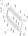
- the superconducting motor 300 therefore comprises the same components as those described above except that each coil 320 of the state of the art is replaced by a coil system 120 according to the invention and shown in FIG. Fig. 2 and which is installed in a pair of orifices 316 of the stator core 314 of the superconducting motor 300.
- the coil system 120 comprises a coil 220 whose constitution is identical to that of the prior art.
- the coil 220 is thus made up of several ribbons 204 with a rectangular section, here three in number, which are joined by their large surfaces, against each other so as to form a stack, and wound on themselves to form generally flat turns.
- Each ribbon 204 is made up of a superconducting material.
- Two successive ribbons 204 in the stack are electrically insulated from each other by a layer of an electrically insulating material, such as a layer of a polyimide varnish, arranged between them, that is to say, an electrically insulating material is arranged between the large surfaces in contact of the two successive ribbons 204.
- an electrically insulating material such as a layer of a polyimide varnish
- the coil 220 has a first straight section 202a which passes through a first orifice 316 of the pair of orifices 316, a second straight section 202b which passes through a second orifice 316 of the pair of orifices 316.
- the first section 202a and the second section 202b each have a first end 206a-b electrically connected to a power source and a second end 208a-b. All of the ribbons 204 are electrically connected to the power source at each first end 206a-b, i.e., current flows through all of the ribbons 204 of the coil 220. The ribbons 204 are thus electrically isolated from each other along the path between the first ends 206a-b but electrically connected at the first ends 206a-b.
- the coil 220 also comprises a winding 210 of at least one turn which connects the second ends 208a-b together.
- the winding 210 comprises rectilinear subsections which pass through one of the two orifices 316 and curved subsections which are outside the orifices 316 and connect the rectilinear sections and subsections together.
- the winding 210 is a single-turn winding and comprises a first straight subsection 210a which passes through the second orifice 316, a second straight subsection 210b which passes through the first orifice 316, a third curved subsection 210c which connects the second end 208a of the first section 202a to the first subsection 210a, a fourth curved subsection 210d which connects the first subsection 210a to the second subsection 210b and a fifth subsection 210e which connects the second subsection 210b to the second end 208b of the second section 202b.
- the coil system 120 also comprises, for each orifice 316 crossed by the coil 220, a shielding system 250.
- the coil system 120 comprises a shielding system 250.
- the shielding system 250 comprises at least one first strip 252a and at least one second strip 252b, where each strip 252a-b is made of an electrically superconductive material, such as a metallic material, and more particularly of the same superconductive material as the ribbons 204 of the coil 220.
- a first first strip 252a is joined by its large surface against the large surface of the rectilinear section or the rectilinear subsection of the coil 220 which is the outermost of the coil 220.
- first strips 252a When there are several first strips 252a, the other first strips 252a are joined by their large surfaces against the large surface of the first first strip 252a joined to the coil 220 and on the other side of said first first strip 252a relative to the coil 220 so as to form a stack which extends towards the outside of the coil 220.
- a first second strip 252b is also abutted by its large surface against the large surface of the rectilinear section or rectilinear subsection of the coil 220 which is the innermost of the coil 220.
- the other second strips 252b are attached by their large surfaces against the large surface of the first second strip 252b attached to the coil 220 and on the other side of said first second strip 252b relative to the coil 220 so as to form a stack which extends towards the inside of the coil 220.
- the strips 252a-b are thus on either side of the rectilinear elements forming the coil 220. On the Fig. 2 , the strips 252a-b are spaced from the reel 220 to facilitate visibility, but they are normally tight against the reel 220.
- Each strip 252a-b which is attached to a ribbon 204 of the coil 220 is electrically insulated from said ribbon 204 by placing a layer of an electrically insulating material, such as a layer of a polyimide varnish, between them.
- None of the strips 252a-b are electrically connected to the power source and thus form a shield around the elements of the coil 220 which are in the holes 316.
- the installation of the shielding systems 250 makes it possible to dissociate the losses due to the passage of current in the coil 220 and the change in polarity of the magnetic field to which the coil 220 is subjected.
- the strips 252a-b interact with the magnetic field and absorb the hysteresis losses.
- each strip 252a-b extends at most over the length of the orifice 316.
- Fig. 3 therefore shows that the number of bands 252a-b influences the losses.
- the current is more than doubled between the state of the art and the invention with six bands 252a-b.
- the resin is impregnated in liquid form and solidification occurs after impregnation.
- the resin used is for example an epoxy resin, the coil 220 and each shielding system 250 are thus embedded in a solid resin.
Landscapes
- Engineering & Computer Science (AREA)
- Power Engineering (AREA)
- Manufacturing & Machinery (AREA)
- Physics & Mathematics (AREA)
- Electromagnetism (AREA)
- Superconductive Dynamoelectric Machines (AREA)
Applications Claiming Priority (1)
| Application Number | Priority Date | Filing Date | Title |
|---|---|---|---|
| FR2305357A FR3149422A1 (fr) | 2023-05-30 | 2023-05-30 | Système de bobine pour un moteur supraconducteur |
Publications (2)
| Publication Number | Publication Date |
|---|---|
| EP4472035A1 true EP4472035A1 (de) | 2024-12-04 |
| EP4472035B1 EP4472035B1 (de) | 2025-07-30 |
Family
ID=87801288
Family Applications (1)
| Application Number | Title | Priority Date | Filing Date |
|---|---|---|---|
| EP24175746.7A Active EP4472035B1 (de) | 2023-05-30 | 2024-05-14 | Spulensystem für einen supraleitenden motor |
Country Status (4)
| Country | Link |
|---|---|
| US (1) | US20260058514A1 (de) |
| EP (1) | EP4472035B1 (de) |
| CN (1) | CN119070519A (de) |
| FR (1) | FR3149422A1 (de) |
Citations (4)
| Publication number | Priority date | Publication date | Assignee | Title |
|---|---|---|---|---|
| JP2011091892A (ja) | 2009-10-20 | 2011-05-06 | Sumitomo Electric Ind Ltd | ステータ、ロータ、および超電導機器 |
| US20120019090A1 (en) | 2010-07-26 | 2012-01-26 | Hitachi, Ltd. | Superconducting coil and superconducting rotating machine using the same |
| EP2717278A1 (de) | 2012-10-05 | 2014-04-09 | Bruker HTS GmbH | Induktiver Fehlerstrombegrenzer mit geteilter Sekundärspulenanordnung |
| CN114421717A (zh) | 2022-01-26 | 2022-04-29 | 华北电力大学(保定) | 一种具有主动磁屏蔽功能的分布式高温超导电枢电机 |
-
2023
- 2023-05-30 FR FR2305357A patent/FR3149422A1/fr not_active Ceased
-
2024
- 2024-05-11 CN CN202410582304.7A patent/CN119070519A/zh active Pending
- 2024-05-14 EP EP24175746.7A patent/EP4472035B1/de active Active
- 2024-05-29 US US18/676,777 patent/US20260058514A1/en active Pending
Patent Citations (4)
| Publication number | Priority date | Publication date | Assignee | Title |
|---|---|---|---|---|
| JP2011091892A (ja) | 2009-10-20 | 2011-05-06 | Sumitomo Electric Ind Ltd | ステータ、ロータ、および超電導機器 |
| US20120019090A1 (en) | 2010-07-26 | 2012-01-26 | Hitachi, Ltd. | Superconducting coil and superconducting rotating machine using the same |
| EP2717278A1 (de) | 2012-10-05 | 2014-04-09 | Bruker HTS GmbH | Induktiver Fehlerstrombegrenzer mit geteilter Sekundärspulenanordnung |
| CN114421717A (zh) | 2022-01-26 | 2022-04-29 | 华北电力大学(保定) | 一种具有主动磁屏蔽功能的分布式高温超导电枢电机 |
Also Published As
| Publication number | Publication date |
|---|---|
| CN119070519A (zh) | 2024-12-03 |
| EP4472035B1 (de) | 2025-07-30 |
| FR3149422A1 (fr) | 2024-12-06 |
| US20260058514A1 (en) | 2026-02-26 |
Similar Documents
| Publication | Publication Date | Title |
|---|---|---|
| EP0097590B1 (de) | Magnetische Lagerung für einen Rotor in einer wasserdichten Umgebung | |
| EP2917999B1 (de) | Synchronmotor mit dauermagneten und elektrischer kompressor mit solch einem elektromotor | |
| FR3046888A1 (fr) | Stator pour machine electromagnetique a flux axial avec des portions unitaires formant une couronne du stator | |
| EP0494810B1 (de) | Verfahren zur Erstellung eines statischen, elektromagnetischen Induktors | |
| EP0214896B1 (de) | Radiales Magnetlager mit grossem Durchmesser | |
| WO2021116575A1 (fr) | Pastille supraconductrice comprenant une cavité et machine électrique associée | |
| EP4472035B1 (de) | Spulensystem für einen supraleitenden motor | |
| FR3086130A1 (fr) | Rotor pour machine electrique asynchrone a arbre non traversant et machine electrique associee | |
| EP2209192A1 (de) | Drehende elektrische Maschine, insbesondere für Kraftfahrzeuganlasser | |
| CA2687070A1 (fr) | Actionneur electromagnetique a reluctance variable | |
| FR2727174A1 (fr) | Palier magnetique a noyau de bobine rapporte | |
| EP3198617B1 (de) | Magnetkern eines rotierenden transformators | |
| WO2012156593A1 (fr) | Turbine génératrice de courant électrique | |
| EP0908961A1 (de) | Verstärker Antrieb von aktiven Materialien | |
| EP4422042B1 (de) | Supraleitender motor mit kühlsystem | |
| EP1481406B1 (de) | Elektromagnetischer aktuator mit kontrollierter anziehungskraft | |
| FR3000282A1 (fr) | Circuit magnetique pour porter au moins une bobine | |
| EP0737988A1 (de) | Feste Induktionsspule für Werfer mit Solenoidinduktion und Werfer mit Solenoidinduktion mit solcher Spule | |
| EP0221921B1 (de) | Eisenloser elektromagnet | |
| FR3131126A1 (fr) | Machine électrique à écrans magnétiques supraconducteurs | |
| WO2025040857A1 (fr) | Moteur electrique a flux axial ameliore | |
| WO2022157441A1 (fr) | Protection des bobines d'une machine électrique | |
| FR3162949A1 (fr) | Machine à flux axial comprenant un corps de rotor monobloc bobiné | |
| EP4282059A1 (de) | Schutz für die spulen einer elektrischen maschine | |
| WO2023152448A1 (fr) | Maschine comprenant pastilles supraconductrices, barriere de flux, bobine supraconductrice annulaire et un induit statorique |
Legal Events
| Date | Code | Title | Description |
|---|---|---|---|
| PUAI | Public reference made under article 153(3) epc to a published international application that has entered the european phase |
Free format text: ORIGINAL CODE: 0009012 |
|
| STAA | Information on the status of an ep patent application or granted ep patent |
Free format text: STATUS: REQUEST FOR EXAMINATION WAS MADE |
|
| 17P | Request for examination filed |
Effective date: 20240514 |
|
| AK | Designated contracting states |
Kind code of ref document: A1 Designated state(s): AL AT BE BG CH CY CZ DE DK EE ES FI FR GB GR HR HU IE IS IT LI LT LU LV MC ME MK MT NL NO PL PT RO RS SE SI SK SM TR |
|
| GRAP | Despatch of communication of intention to grant a patent |
Free format text: ORIGINAL CODE: EPIDOSNIGR1 |
|
| STAA | Information on the status of an ep patent application or granted ep patent |
Free format text: STATUS: GRANT OF PATENT IS INTENDED |
|
| INTG | Intention to grant announced |
Effective date: 20250519 |
|
| GRAS | Grant fee paid |
Free format text: ORIGINAL CODE: EPIDOSNIGR3 |
|
| GRAA | (expected) grant |
Free format text: ORIGINAL CODE: 0009210 |
|
| STAA | Information on the status of an ep patent application or granted ep patent |
Free format text: STATUS: THE PATENT HAS BEEN GRANTED |
|
| AK | Designated contracting states |
Kind code of ref document: B1 Designated state(s): AL AT BE BG CH CY CZ DE DK EE ES FI FR GB GR HR HU IE IS IT LI LT LU LV MC ME MK MT NL NO PL PT RO RS SE SI SK SM TR |
|
| REG | Reference to a national code |
Ref country code: GB Ref legal event code: FG4D Free format text: NOT ENGLISH |
|
| REG | Reference to a national code |
Ref country code: CH Ref legal event code: EP |
|
| REG | Reference to a national code |
Ref country code: DE Ref legal event code: R096 Ref document number: 602024000357 Country of ref document: DE |
|
| REG | Reference to a national code |
Ref country code: IE Ref legal event code: FG4D Free format text: LANGUAGE OF EP DOCUMENT: FRENCH |
|
| REG | Reference to a national code |
Ref country code: NL Ref legal event code: MP Effective date: 20250730 |
|
| REG | Reference to a national code |
Ref country code: AT Ref legal event code: MK05 Ref document number: 1820115 Country of ref document: AT Kind code of ref document: T Effective date: 20250730 |
|
| PG25 | Lapsed in a contracting state [announced via postgrant information from national office to epo] |
Ref country code: PT Free format text: LAPSE BECAUSE OF FAILURE TO SUBMIT A TRANSLATION OF THE DESCRIPTION OR TO PAY THE FEE WITHIN THE PRESCRIBED TIME-LIMIT Effective date: 20251202 |
|
| PG25 | Lapsed in a contracting state [announced via postgrant information from national office to epo] |
Ref country code: IS Free format text: LAPSE BECAUSE OF FAILURE TO SUBMIT A TRANSLATION OF THE DESCRIPTION OR TO PAY THE FEE WITHIN THE PRESCRIBED TIME-LIMIT Effective date: 20251130 |
|
| PG25 | Lapsed in a contracting state [announced via postgrant information from national office to epo] |
Ref country code: NO Free format text: LAPSE BECAUSE OF FAILURE TO SUBMIT A TRANSLATION OF THE DESCRIPTION OR TO PAY THE FEE WITHIN THE PRESCRIBED TIME-LIMIT Effective date: 20251030 |
|
| REG | Reference to a national code |
Ref country code: LT Ref legal event code: MG9D |
|
| PG25 | Lapsed in a contracting state [announced via postgrant information from national office to epo] |
Ref country code: AT Free format text: LAPSE BECAUSE OF FAILURE TO SUBMIT A TRANSLATION OF THE DESCRIPTION OR TO PAY THE FEE WITHIN THE PRESCRIBED TIME-LIMIT Effective date: 20250730 |
|
| PG25 | Lapsed in a contracting state [announced via postgrant information from national office to epo] |
Ref country code: FI Free format text: LAPSE BECAUSE OF FAILURE TO SUBMIT A TRANSLATION OF THE DESCRIPTION OR TO PAY THE FEE WITHIN THE PRESCRIBED TIME-LIMIT Effective date: 20250730 |
|
| PG25 | Lapsed in a contracting state [announced via postgrant information from national office to epo] |
Ref country code: HR Free format text: LAPSE BECAUSE OF FAILURE TO SUBMIT A TRANSLATION OF THE DESCRIPTION OR TO PAY THE FEE WITHIN THE PRESCRIBED TIME-LIMIT Effective date: 20250730 Ref country code: NL Free format text: LAPSE BECAUSE OF FAILURE TO SUBMIT A TRANSLATION OF THE DESCRIPTION OR TO PAY THE FEE WITHIN THE PRESCRIBED TIME-LIMIT Effective date: 20250730 |
|
| PG25 | Lapsed in a contracting state [announced via postgrant information from national office to epo] |
Ref country code: GR Free format text: LAPSE BECAUSE OF FAILURE TO SUBMIT A TRANSLATION OF THE DESCRIPTION OR TO PAY THE FEE WITHIN THE PRESCRIBED TIME-LIMIT Effective date: 20251031 |
|
| PG25 | Lapsed in a contracting state [announced via postgrant information from national office to epo] |
Ref country code: SE Free format text: LAPSE BECAUSE OF FAILURE TO SUBMIT A TRANSLATION OF THE DESCRIPTION OR TO PAY THE FEE WITHIN THE PRESCRIBED TIME-LIMIT Effective date: 20250730 |
|
| PG25 | Lapsed in a contracting state [announced via postgrant information from national office to epo] |
Ref country code: LV Free format text: LAPSE BECAUSE OF FAILURE TO SUBMIT A TRANSLATION OF THE DESCRIPTION OR TO PAY THE FEE WITHIN THE PRESCRIBED TIME-LIMIT Effective date: 20250730 |
|
| PG25 | Lapsed in a contracting state [announced via postgrant information from national office to epo] |
Ref country code: BG Free format text: LAPSE BECAUSE OF FAILURE TO SUBMIT A TRANSLATION OF THE DESCRIPTION OR TO PAY THE FEE WITHIN THE PRESCRIBED TIME-LIMIT Effective date: 20250730 Ref country code: PL Free format text: LAPSE BECAUSE OF FAILURE TO SUBMIT A TRANSLATION OF THE DESCRIPTION OR TO PAY THE FEE WITHIN THE PRESCRIBED TIME-LIMIT Effective date: 20250730 |
|
| PG25 | Lapsed in a contracting state [announced via postgrant information from national office to epo] |
Ref country code: RS Free format text: LAPSE BECAUSE OF FAILURE TO SUBMIT A TRANSLATION OF THE DESCRIPTION OR TO PAY THE FEE WITHIN THE PRESCRIBED TIME-LIMIT Effective date: 20251030 |
|
| PG25 | Lapsed in a contracting state [announced via postgrant information from national office to epo] |
Ref country code: ES Free format text: LAPSE BECAUSE OF FAILURE TO SUBMIT A TRANSLATION OF THE DESCRIPTION OR TO PAY THE FEE WITHIN THE PRESCRIBED TIME-LIMIT Effective date: 20250730 |
|
| PG25 | Lapsed in a contracting state [announced via postgrant information from national office to epo] |
Ref country code: SM Free format text: LAPSE BECAUSE OF FAILURE TO SUBMIT A TRANSLATION OF THE DESCRIPTION OR TO PAY THE FEE WITHIN THE PRESCRIBED TIME-LIMIT Effective date: 20250730 |
|
| PG25 | Lapsed in a contracting state [announced via postgrant information from national office to epo] |
Ref country code: DK Free format text: LAPSE BECAUSE OF FAILURE TO SUBMIT A TRANSLATION OF THE DESCRIPTION OR TO PAY THE FEE WITHIN THE PRESCRIBED TIME-LIMIT Effective date: 20250730 |
|
| PG25 | Lapsed in a contracting state [announced via postgrant information from national office to epo] |
Ref country code: IT Free format text: LAPSE BECAUSE OF FAILURE TO SUBMIT A TRANSLATION OF THE DESCRIPTION OR TO PAY THE FEE WITHIN THE PRESCRIBED TIME-LIMIT Effective date: 20250730 |
|
| PG25 | Lapsed in a contracting state [announced via postgrant information from national office to epo] |
Ref country code: CZ Free format text: LAPSE BECAUSE OF FAILURE TO SUBMIT A TRANSLATION OF THE DESCRIPTION OR TO PAY THE FEE WITHIN THE PRESCRIBED TIME-LIMIT Effective date: 20250730 |
|
| PG25 | Lapsed in a contracting state [announced via postgrant information from national office to epo] |
Ref country code: SK Free format text: LAPSE BECAUSE OF FAILURE TO SUBMIT A TRANSLATION OF THE DESCRIPTION OR TO PAY THE FEE WITHIN THE PRESCRIBED TIME-LIMIT Effective date: 20250730 Ref country code: EE Free format text: LAPSE BECAUSE OF FAILURE TO SUBMIT A TRANSLATION OF THE DESCRIPTION OR TO PAY THE FEE WITHIN THE PRESCRIBED TIME-LIMIT Effective date: 20250730 |